1
Dialogic ® DSI Signaling Servers
SNMP User Manual
www.dialogic.com
Copyright and Legal Notice
Copyright© 2012. Dialogic Inc. All Rights Reserved. You may not reproduce this document in whole or in part without permission in
writing from Dialogic Inc. at the address provided below.
All contents of this document are furnished for informational use only and are subject to change without notice and do not represent a
commitment on the part of Dialogic Inc. and its affiliates or subsidiaries (“Dialogic”). Reasonable effort is made to ensure the accuracy
of the information contained in the document. However, Dialogic does not warrant the accuracy of this information and cannot accept
responsibility for errors, inaccuracies or omissions that may be contained in this document.
INFORMATION IN THIS DOCUMENT IS PROVIDED IN CONNECTION WITH DIALOGIC PRODUCTS. NO LICENSE, EXPRESS OR IMPLIED,
BY ESTOPPEL OR OTHERWISE, TO ANY INTELLECTUAL PROPERTY RIGHTS IS GRANTED BY THIS DOCUMENT. EXCEPT AS PROVIDED IN
A SIGNED AGREEMENT BETWEEN YOU AND DIALOGIC, DIALOGIC ASSUMES NO LIABILITY WHATSOEVER, AND DIALOGIC DISCLAIMS
ANY EXPRESS OR IMPLIED WARRANTY, RELATING TO SALE AND/OR USE OF DIALOGIC PRODUCTS INCLUDING LIABILITY OR
WARRANTIES RELATING TO FITNESS FOR A PARTICULAR PURPOSE, MERCHANTABILITY, OR INFRINGEMENT OF ANY INTELLECTUAL
PROPERTY RIGHT OF A THIRD PARTY.
Dialogic products are not intended for use in certain safety-affecting situations. Please see http://www.dialogic.com/about/legal.htm for
more details.
Due to differing national regulations and approval requirements, certain Dialogic products may be suitable for use only in specific
countries, and thus may not function properly in other countries. You are responsible for ensuring that your use of such products occurs
only in the countries where such use is suitable. For information on specific products, contact Dialogic Inc. at the address indicated
below or on the web at www.dialogic.com.
It is possible that the use or implementation of any one of the concepts, applications, or ideas described in this document, in marketing
collateral produced by or on web pages maintained by Dialogic may infringe one or more patents or other intellectual property rights
owned by third parties. Dialogic does not provide any intellectual property licenses with the sale of Dialogic products other than a
license to use such product in accordance with intellectual property owned or validly licensed by Dialogic and no such licenses are
provided except pursuant to a signed agreement with Dialogic. More detailed information about such intellectual property is available
from Dialogic‟s legal department at 9800 Cavendish Blvd., Suite 500, Montreal, Quebec, Canada H4M 2V9. Dialogic encourages all
users of its products to procure all necessary intellectual property licenses required to implement any concepts or
applications and does not condone or encourage any intellectual property infringement and disclaims any responsibility
related thereto. These intellectual property licenses may differ from country to country and it is the responsibility of
those who develop the concepts or applications to be aware of and comply withdifferent national license requirements.
Dialogic, Dialogic Pro, Dialogic Blue, Veraz, Brooktrout, Diva, Diva ISDN, Making Innovation Thrive, Video is the New Voice,
VisionVideo, Diastar, Cantata, TruFax, SwitchKit, SnowShore, Eicon, Eiconcard, NMS Communications, NMS (stylized), SIPcontrol,
Exnet, EXS, Vision, PowerMedia, PacketMedia, BorderNet, inCloud9, I-Gate, ControlSwitch, NaturalAccess, NaturalCallControl,
NaturalConference, NaturalFax and Shiva, among others as well as related logos, are either registered trademarks or trademarks of
Dialogic Inc. and its affiliates or subsidiaries. Dialogic's trademarks may be used publicly only with permission from Dialogic. Such
permission may only be granted by Dialogic‟s legal department at 9800 Cavendish Blvd., Suite 500, Montreal, Quebec, Canada H4M
2V9. Any authorized use of Dialogic's trademarks will be subject to full respect of the trademark guidelines published by Dialogic from
time to time and any use of Dialogic‟s trademarks requires proper acknowledgement. .
The names of actual companies and products mentioned herein are the trademarks of their respective owners.
Publication Date: May 2012
2
Dialogic® DSI Signaling Servers SNMP User Manual Issue 3
Contents
Revision History ........................................................................................................... 5
1
Introduction ........................................................................................................ 7
1.1
1.2
1.3
Overview ............................................................................................................................... 7
Applicability ........................................................................................................................... 8
Related Documentation............................................................................................................ 8
2
Activation and Configuration ............................................................................... 9
2.1
Overview ............................................................................................................................... 9
3
The DSMI MIB Structure .................................................................................... 11
3.1
3.2
3.3
3.4
Enterprise/Family MIB Structure ............................................................................................. 11
The Signaling Server Object Groups and Objects....................................................................... 11
The MIB Files........................................................................................................................ 12
Components of an Object ....................................................................................................... 14
3.4.1
Introduction 14
3.4.2
The Administration Table ........................................................................................... 14
3.4.3
The Object Table ...................................................................................................... 15
4
The DSMI Object Groups and Objects ................................................................ 17
4.1
DSMI-MANAGEMENT-OBJECTS-MIB (The Management Object Group) .......................................... 18
4.1.1
snmpAgentConfigurationObjectTable ........................................................................... 18
4.1.2
snmpMgrConfigurationObjectTable .............................................................................. 19
4.1.3
snmpUserConfigurationObjectTable............................................................................. 20
DSMI-SYSTEM-OBJECTS-MIB (The System Object Group) .......................................................... 20
4.2.1
sysDataObjectTable .................................................................................................. 20
4.2.2
capDataObjectTable .................................................................................................. 22
4.2.3
serverLinkObjectTable ............................................................................................... 23
4.2.4
peerLinkObjectTable ................................................................................................. 24
4.2.5
clientLinkObjectTable ................................................................................................ 24
4.2.6
RDCObjectTable ....................................................................................................... 25
4.2.7
cRecordObjectTable .................................................................................................. 25
4.2.8
pReportObjectTable .................................................................................................. 26
DSMI-PLATFORM-OBJECTS-MIB (The Platform Object Group) ..................................................... 26
4.3.1
memoryObjectTable .................................................................................................. 26
4.3.2
cpuObjectTable ........................................................................................................ 27
4.3.3
psuObjectTable ........................................................................................................ 27
4.3.4
fanObjectTable ......................................................................................................... 28
4.3.5
driveObjectTable ...................................................................................................... 28
DSMI-IP-OBJECTS-MIB (The IP Object Group) .......................................................................... 29
4.4.1
ethObjectTable ......................................................................................................... 29
DSMI-BOARD-OBJECTS-MIB (The Board Object Group) ............................................................. 29
4.5.1
boardObjectTable ..................................................................................................... 29
4.5.2
pcmObjectTable ....................................................................................................... 30
DSMI-SS7-OBJECTS-MIB (The SS7 Object Group)..................................................................... 31
4.6.1
ss7LsObjectTable ...................................................................................................... 31
4.6.2
ss7LinkObjectTable ................................................................................................... 32
4.6.3
ss7RouteObjectTable................................................................................................. 32
DSMI-SIGTRAN-OBJECTS-MIB (The SIGTRAN Object Group) ...................................................... 33
4.7.1
snLnkObjectTable ..................................................................................................... 33
4.7.2
sinRASObjectTable.................................................................................................... 34
4.7.3
snRtObjectTable ....................................................................................................... 34
DSMI-ACCESS-OBJECTS-MIB (The Access Object Group) ........................................................... 35
4.8.1
AccessLinkObjectTable .............................................................................................. 35
4.2
4.3
4.4
4.5
4.6
4.7
4.8
3
Contents
5
Signaling Server Notifications (TRAPs) ............................................................. 36
5.1
5.2
The Role of an Object‟s Administration Table ............................................................................ 36
Trap Notification Fields .......................................................................................................... 37
6
MMI commands ................................................................................................. 44
6.1
6.2
6.3
6.4
6.5
6.6
6.7
6.8
6.9
6.10
6.11
6.12
6.13
6.14
CNSNP – Display SNMP Configuration ...................................................................................... 44
CNSNS – Set SNMP Configuration ........................................................................................... 45
CNOBS – Set TRAP Configuration ............................................................................................ 45
CNOBP – Display TRAP Configuration ...................................................................................... 46
CNSMI – Set SNMP Manager Configuration............................................................................... 47
CNSMC – Change SNMP Manager Configuration ........................................................................ 48
CNSME – End SNMP Manager Configuration ............................................................................. 49
CNSMP – Display SNMP Manager Configuration ........................................................................ 49
CNUSI – Set SNMP v3 ........................................................................................................... 50
CNUSC – Change SNMP v3 User Configuration.......................................................................... 51
CNUSE – End SNMP v3 .......................................................................................................... 51
CNUSP – Display SNMP v3 ..................................................................................................... 52
CNSYS – Set System Configuration ......................................................................................... 53
CNSYP – Display System Configuration .................................................................................... 53
7
License .............................................................................................................. 54
7.1
7.2
Introduction ......................................................................................................................... 54
License ................................................................................................................................ 54
Figures
Figure 1.
4
Structure and Location of the Dialogic® DSI Signaling Server Groups and their Component
Objects .................................................................................................................. 11
Dialogic® DSI Signaling Servers SNMP User Manual Issue 3
Revision History
Issue
Date
Description
3
May 2012
Updated to incorporate information for the Dialogic® DSI SS7G41
Signaling Server.
2
August 2008
Updated to incorporate information for the Dialogic® DSI SS7G31 and
SS7G32 Signaling Servers.
1
January 2008
Manual created.
Note:
The current release of this guide can be found at:
http://www.dialogic.com/support/helpweb/signaling
5
Revision History
6
Dialogic® DSI Signaling Servers SNMP User Manual Issue 3
1
Introduction
Contents
1.1
1.2
1.3
1.1
Overview…7
Applicability…8
Related Documentation…8
Overview
This document is a supplement to the Dialogic® DSI Signaling Server user
manuals describing the operation and capabilities of the Distributed
Structured Management Information (DSMI) SNMP agent as it is used on the
Dialogic® DSI Signaling Server in SIU and SGW modes.
The existing, basic SNMP agent is already described by the User Manuals and
therefore no further reference is made to it in this manual.
DSMI SNMP operation provides comprehensive reporting of the state and
alarms for Dialogic® DSI Signaling Server components (e.g., board instances,
SS7 links, fans etc.) through SNMP. This information is classified into the
following object groups:
Management
System
Platform
IP
Boards
SS7
SIGTRAN
Access.
Each of these object groups comprise one or more objects. These objects,
together with the object groups, are defined in separate SNMP MIB definition
files. This implementation of the DSMI SNMP agent only supports „read‟
(SNMP GET) requests from SNMP managers. There is no support for „write‟
(SNMP PUT) requests.
DSMI SNMP support is implemented as a SNMP subagent and provides
support of SNMP versions 1 (RFC1157), 2c (RFC1901) and 3 (RFC2571).
The DSMI SNMP agent provides status information about various aspects of
the Server‟s behavior. It also implements SNMP TRAP/NOTIFY events alerting
SNMP manager software to various conditions that the agent has detected.
Up to 32 SNMP managers can be defined to receive TRAP notifications. These
managers can be configured to receive TRAP notifications supported by the
various versions of SNMP.
7
Section 1
Introduction
As well as supporting the DSMI MIB set, the SNMP agent on the Dialogic® DSI
Signaling Server provides support for a number of standard MIBs. A user can
get further IP related data by accessing the IF-MIB, RFC1213-MIB, IP-MIB,
TCP-MIB and UDP-MIB. A user can get further information on the operation
of the underlying server platform by accessing the HOST-RESOURCES-MIB.
Finally, the Signaling Server also provides support for the Systems Group of
the SNMPv2-MIB and is capable of generating a standard cold-start trap.
1.2
Applicability
This document is applicable to the following:
Dialogic® DSI SS7G30 products, SIU release 2.2.2 or later, or SGW
release 2.2.0 or later.
Dialogic® DSI SS7G41 SIU release 1.0.3 or later, or SWS release 1.0.3 or
later.
Dialogic® DSI DSMI MIB package v2.02 or later.
1.3
Related Documentation
[1] Dialogic® DSI Signaling Servers SS7G3x SIU Mode User Manual
[2] Dialogic® DSI Signaling Servers SS7G3x SGW Mode User Manual
[3] Dialogic® DSI Signaling Servers SS7G41 Operators Manual
8
Dialogic® DSI Signaling Servers SNMP User Manual Issue 3
2
Activation and Configuration
2.1
Overview
To activate DSMI SNMP on SS7G30 systems the user should use the CNSNS
command to set SNMP to DSMI and restart the system to allow activation of
the agent.
To activate DSMI SNMP on SS7G41 system the user should use the CNSNS
command to set SNMP to Y and restart the system to allow activation of the
agent.
Once active, the DSMI SNMP agent is able to respond to SNMP requests. If
the user wishes the system to send SNMP TRAPs to a particular SNMP
manager, the manager should be configured using the CNSMI command.
By default, once a SNMP manager is configured the DSMI SNMP agent will
send a TRAP when it detects a change in state of a DSMI Object. A user may
disable trapping for particular objects or extend trapping to configuration
events for the object through use of the CNOBS command.
An SNMP manager may be configured through use of the CNSMx commands
to receive SNMP v1, v2c or v3 format TRAPs. If a SNMP v3 trap is required
then the SNMP „user‟ must first be specified through use of the CNUSx
command.
Refer to Section 6: MMI commands on page 44 for definitions of the
commands and how they are used.
9
Section 2
10
Activation and Configuration
Dialogic® DSI Signaling Servers SNMP User Manual Issue 3
3
The DSMI MIB Structure
Contents
3.1
3.2
3.3
3.4
3.1
Enterprise/Family MIB Structure…11
The Signaling Server Object Groups and Objects…11
The MIB Files…12
Components of an Object…14
3.4.1
Introduction…14
3.4.2
The Administration Table…14
3.4.3
The Object Table…15
Enterprise/Family MIB Structure
The Dialogic® DSI Signaling Server MIBS and NOTIFICATION definitions are
located under the Dialogic® dlgDSMI OID (.1.3.6.1.4.1.3028.6.2). From this
OID, there are two branches: branch 3028.6.2.1 represents the signaling
server objects, whereas branch 3028.6.2.2 is used to hold the NOTIFICATION
definitions (3028.6.2.2.1) and textual conventions (3028.6.2.2.2).
3.2
The Signaling Server Object Groups and Objects
The following diagram represents the structure and location of the Signaling
Server groups and their component objects.
Figure 1.
Structure and Location of the Dialogic® DSI Signaling Server Groups and
their Component Objects
1
2
3
4
5
6
7
8
Management
System
Platform
IP
Boards
SS7
SIGTRAN
Access
1
SNMP Agent
Configuration
System
Data
Memory
Ethernet
Ports
Boards
SS7
Linksets
SIGTRAN
Links
Access
Links
2
SNMP Manager
Configuration
Capability
CPU
PCMs
SS7
Links
SIGTRAN
RAS
3
SNMP User
Configuration
Server
Links
PSU
SS7
Routes
SIGTRAN
Routes
4
Peer Links
Fans
5
Client
Links
Drives
6
RDC
7
Continuous
Record
8
Periodic
Report
11
Section 3
The DSMI MIB Structure
An object is referenced by specifying its object group identifier followed by its
own identifier. For example, the Drives object (in the Platform group) is
referenced as 3.5. Its fully qualified OID, therefore, is
.1.3.6.1.4.1.3028.6.2.1.3.5.
3.3
The MIB Files
There is one MIB definition file per object group as well as additional MIB
definition files which define the location of the DSMI objects within the SNMP
object hierarchy (DSMI-SMI), the textual conventions used in defining the
objects (DSMI-TC) and the notifications generated by the DSMI SNMP agent
(DSMI-NOTIFICATION).
The MIB definition files give the object groups and objects more user-friendly
names. The following diagrams depict the user-friendly names of the object
groups and their respective objects.
DSMI-MANAGEMENT-OBJECTS-MIB
snmpAgentConfiguration
snmpManagerConfiguration
snmpUserConfiguration
DSMI-SYSTEM-OBJECTS-MIB
systemData
capabilityData
serverLinks
peerLinks
clientLinks
rdcs
continuousRecords
periodicReports
DSMI-PLATFORM-OBJECTS-MIB
memory
cpu
psu
fan
drives
12
Dialogic® DSI Signaling Servers SNMP User Manual Issue 3
DSMI-IP-OBJECTS-MIB
ethernetPorts
DSMI-BOARD-OBJECTS-MIB
boards
pcms
DSMI-SS7-OBJECTS-MIB
ss7Linksets
ss7Links
ss7Routes
DSMI-SIGTRAN-OBJECTS-MIB
sigtranLinks
sigtranRAS
sigtranRoutes
DSMI-ACCESS-OBJECTS-MIB
accessLinks
It is recommended that the user load the DSMI-SMI, DSMI-TC and DSMINOTIFICATION MIBs, as well as all relevant object group MIBs into their
SNMP manager.
13
Section 3
The DSMI MIB Structure
3.4
Components of an Object
3.4.1
Introduction
Each object comprises two tables. The first table, or the object table, holds
status data about the object, whereas the second table, or the
administration table, details the number of rows in the table as well as the
current TRAP configuration settings for the object. The object table resides at
OID x.y.1 (where x is the object group identifier and y is the object
identifier). The administration table resides at OID x.y.2. For example, the
AccessLink object table is found at .1.3.6.1.4.1.3028.6.2.1.8.1.1, and the
administration table is located at .1.3.6.1.4.1.3028.6.2.1.8.1.2. The
administration and objects tables are now described. Whereas the
administration table serves a common object-independent function across all
objects, the object table has contains attributes which may have objectdependent meaning.
3.4.2
The Administration Table
The administration table has the following columns:
Column Name
dsmiadm…AdminIndex
Description
As there is only one row in this table, this value is always
zero.
dsmiadm…UpCount
dsmiadm…DownCount
dsmiadm…InactiveCount
dsmiadm…ImpairedCount
dsmiadm…RestartingCount
These count values report the number of rows in the
specified state. For example, the UpCount value reports
the number of rows in the Up state.
dsmiadm…QuiescingCount
dsmiadm…WarningCount
dsmiadm…TotalRowCount
The total number of rows in the object table.
dsmiadm…UpTrapConfigure
dsmiadm…DownTrapConfigure
dsmiadm…InactiveTrapConfigure
dsmiadm…ImpairedTrapConfigure
dsmiadm…RestartingTrapConfigure
dsmiadm…QuiescingTrapConfigure
dsmiadm…WarningTrapConfigure
14
These values determine the conditions under which a trap
will be generated. Each Configure field can be set to
generate a trap when a row is created, changed, or
destroyed with the given state. Furthermore, the field can
be set to ‘none’ so that no trap is generated or ‘all’ so that
a trap is generated, when any operation (create, change
or destroy) is executed on a row within the object table.
These settings are controlled by the CNOBS command,
which displays the current trap configuration.
Dialogic® DSI Signaling Servers SNMP User Manual Issue 3
3.4.3
The Object Table
The object table consists of a common set of columns that are to be found in
every object. There may be one or more rows in the object table. This will
depend on the functionality being represented by the object. In addition to
these columns, some objects have object-specific columns that provide extra
information pertaining to the object in question. The common columns are as
follows:
Column Name
Data Type
Description
dsmiHeadIndex
ASN_INTEGER
The row index
dsmiHeadRowStatus
RowStatus
Used for row maintenance
dsmiHeadTimeInState
TimeTicks
The duration of time that
the object has been in the
current state
dsmiHeadIdVal
ASN_UNSIGNED32
A unique identifier for the
row
dsmiHeadIdDescription
DisplayString
A string that holds objectspecific information
dsmiHeadState
DSMI-OBJSTATE
The current state of the
object
dsmiOwnerId
OCTET STRING
Reserved.
This field is not used on the
Signaling Server. No
further reference will be
made to the field within this
document.
The following section describes each object in greater detail with reference to
the common header columns and, if relevant, additional columns that are
associated with the object. If the common header fields in an object have
object-specific behavior, the details are given. If no details are given for one
of the common header fields, it can be assumed that the general purpose
description given above applies.
15
Section 3
16
The DSMI MIB Structure
Dialogic® DSI Signaling Servers SNMP User Manual Issue 3
4
The DSMI Object Groups and Objects
Contents
4.1
4.2
4.3
4.4
4.5
4.6
4.7
4.8
DSMI-MANAGEMENT-OBJECTS-MIB (The Management Object Group)…18
4.1.1
snmpAgentConfigurationObjectTable…18
4.1.2
snmpMgrConfigurationObjectTable…19
4.1.3
snmpUserConfigurationObjectTable…20
DSMI-SYSTEM-OBJECTS-MIB (The System Object Group)…20
4.2.1
systemDataObjectTable…20
4.2.2
capabilityDataObjectTable…22
4.2.3
serverLinkObjectTable…23
4.2.4
peerLinkObjectTable…24
4.2.5
clientLinkObjectTable…24
4.2.6
RDCObjectTable…25
4.2.7
cRecordObjectTable…25
4.2.8
pReportObjectTable…26
DSMI-PLATFORM-OBJECTS-MIB (The Platform Object Group)…26
4.3.1
memoryObjectTable…26
4.3.2
cpuObjectTable…27
4.3.3
psuObjectTable…27
4.3.4
fanObjectTable…28
4.3.5
drivesObjectTable…28
DSMI-IP-OBJECTS-MIB (The IP Object Group)…29
4.4.1
ethernetObjectTable…29
DSMI-BOARD-OBJECTS-MIB (The Board Object Group)…29
4.5.1
boardsObjectTable…29
4.5.2
pcmsObjectTable…30
DSMI-SS7-OBJECTS-MIB (The SS7 Object Group)…31
4.6.1
ss7LinksetsObjectTable…31
4.6.2
ss7LinksObjectTable…32
4.6.3
ss7RoutesObjectTable…32
DSMI-SIGTRAN-OBJECTS-MIB (The SIGTRAN Object Group)…33
4.7.1
sigtranLinksObjectTable…33
4.7.2
sigtranRASObjectTable…34
4.7.3
sigtranRoutesObjectTable…34
DSMI-ACCESS-OBJECTS-MIB (The Access Object Group)…35
4.8.1
AccessLinkObjectTable…35
17
Section 4
4.1
The DSMI Object Groups and Objects
DSMI-MANAGEMENT-OBJECTS-MIB (The
Management Object Group)
This MIB gathers together the data pertaining to the SNMP configuration of
the Dialogic® DSI Signaling Server. There are three objects which go to make
up this group. These objects and their attributes are now described in greater
detail.
4.1.1
snmpAgentConfigurationObjectTable
This object represents the single SNMP master agent (i.e., there is only one
row) that runs on the server.
Column Name
Column Description
dsmiSNMPAgentHeadIndex
-
dsmiSNMPAgentHeadRowStatus
-
dsmiSNMPAgentHeadTimeInState
-
dsmiSNMPAgentHeadIdVal
-
dsmiSNMPAgentHeadIdDescription
-
dsmiSNMPAgentHeadState
up
The SNMP agent can
communicate with managers
impaired
The Signaling Server does not
have a valid network time source
(only occurs if the server has
been configured to synchronize
its clock with an NTP server)
quiescing
The SNMP agent is being
disabled
18
dsmiSNMPAgentRoCommunity
The SNMP read-only access community
string (not accessible) by remote SNMP
managers)
dsmiSNMPAgentRwCommunity
The SNMP read-write access community
string (not accessible by remote SNMP
managers)
dsmiSNMPAgentPort
The port on which the SNMP agent will
communicate with remote SNMP
managers
Dialogic® DSI Signaling Servers SNMP User Manual Issue 3
4.1.2
snmpMgrConfigurationObjectTable
This object represents the remote SNMP managers to which SNMP traps are
sent.
Column Name
dsmiSNMPMgrHeadIndex
Column Description
-
dsmiSNMPMgrHeadRowStatus
-
dsmiSNMPMgrHeadTimeInState
-
dsmiSNMPMgrHeadIdVal
The SNMP manager instance
dsmiSNMPMgrHeadIdDescription
dsmiSNMPMgrHeadState
up
The SNMP manager is
configured and will receive
TRAP-related notifications
restarting
The SNMP manager is being
added and will soon be
available
quiescing
The SNMP manager is being
removed
dsmiSNMPMgrIpAddress
The IP address of the SNMP
manager
dsmiSNMPMgrTrapPort
The socket/port which will receive
TRAP-related notifications
dsmiSNMPMgrCommunityString
The TRAP community string (SNMP
v1,v2c)
dsmiSNMPMgrTrapType
Specifies the type of event that will be
dispatched to the manager:
1
v1 TRAP
2
v2 NOTIFICATION
3
v2 INFORM
dsmiSNMPMgrUserID
If a user identifier value is specified
here, it refers to a user in the
snmpUserConfigurationObjectTable
which defines the SNMP v3
credentials to be used when sending
an SNMP v3 TRAP to the abovespecified SNMP manager.
dsmiSNMPMgrEngineId
This parameter is used in conjunction
with an SNMP v3 TRAP. This value
must match the engine identifier
value which has been configured on
the remote SNMP manager so that v3
TRAP messages can be received
properly
19
Section 4
4.1.3
The DSMI Object Groups and Objects
snmpUserConfigurationObjectTable
This object represents the different SNMP V3 users that are registered on the
local machine. It is also used to define SNMP v3 users registered with SNMP
managers (see snmpMgrConfigurationObjectTable above) for receipt of TRAP
events.
Column Name
Column Description
dsmiSNMPUserHeadIndex
-
dsmiSNMPUserHeadRowStatus
-
dsmiSNMPUserHeadTimeInState
-
dsmiSNMPUserHeadIdVal
The user’s unique identifier in this
object (i.e., not the user name)
dsmiSNMPUserHeadIdDescription
-
dsmiSNMPUserHeadState
up
The user is configured
quiescing
The user is being removed
4.2
dsmiSNMPUserUserName
The user name
dsmiSNMPUserSecurityLevel
The SNMP v3 security level
(noAuthNoPriv, authNoPriv or
authPriv)
dsmiSNMPUserAuthenticationProtocol
MD5 or SHA1 algorithm
dsmiSNMPUserAuthenticationPassphrase
The authentication
secret/password
dsmiSNMPUserPrivacyProtocol
AES or DES algorithm
dsmiSNMPUserPrivacyPassphrase
The encryption secret/password
DSMI-SYSTEM-OBJECTS-MIB (The System
Object Group)
This object group represents various software-related entities within the
Signaling Server.
4.2.1
sysDataObjectTable
This object identifies system-specific information. There is only one row in
this object table.
Column Name
20
Column Description
dsmiSysDataHeadIndex
-
dsmiSysDataHeadRowStatus
-
dsmiSysDataHeadTimeInState
-
dsmiSysDataHeadIdVal
The system reference
dsmiSysDataHeadIdDescription
The unit ID of the system
Dialogic® DSI Signaling Servers SNMP User Manual Issue 3
Column Name
dsmiSysDataHeadState
Column Description
up
The system is up
impaired
The system is in overload
restarting
The system is starting
quiescing
The system is shutting down
warning
The system needs to be restarted or is running
in trial mode
dsmiSysDataPlatformType
The type of system. This field will have one of these
values:
SS7G41 (1)
The system is a Dialogic® DSI SS7G31 Signaling
Server
Reserved (2)
This value is reserved
Reserved (3)
This value is reserved
Reserved (4)
This value is reserved
SS7G2x (5)
The system is a Dialogic® DSI SS7G21 or
SS7G22 Signaling Server
SS7G31 (6)
The system is a Dialogic® DSI SS7G31
Signaling Server
SS7G32 (7)
The system is a Dialogic® DSI SS7G32
Signaling Server
dsmiSysDataSysVer
The software version of the software distribution
dsmiSysDataPlatVer
The software version of the platform specific
distribution
dsmiSysDataSysContact
Contact details for the system
dsmiSysDataSysName
The host name assigned to the system
dsmiSysDataSysLocation
The physical location of the system
dsmiSysDataSysType
One of the following values:
Reserved (1)
The server is not running in a recognized mode
SIU (2)
The server is running in SIU mode
SGW (3)
The server is running in SGW mode
DSC (4)
The server is running in DSC mode
SWS (5)
21
Section 4
The DSMI Object Groups and Objects
Column Name
Column Description
The server is running in SWS mode
4.2.2
capDataObjectTable
This object describes the capabilities of the system in terms of the various
license statuses.
Column Name
Column Description
dsmiCapDataHeadIndex
-
dsmiCapDataHeadRowStatus
-
dsmiCapDataHeadTimeInState
-
dsmiCapDataHeadIdVal
dsmiCapDataHeadIdDescription
ThedsmiHeadIDVal and dsmiHeadIdDescription will
identify the following capabilities as a numerical
value and associated strings. This table shows the
possible HeadIdVal values and their corresponding
HeadIdDescription values:
For the SS7G41 the following identifiers are
used:
1 SIU
2 SWS
3 M2PA
4 M3UA
5 MTP
6 TCAP
7 MAP
8 INAP
9 IS41
10 Reserved
11 Reserved
For earlier Signaling Server Generations the
following identifiers are used:
1 SIU
2 SGW
3 DSC
4 SCTP
5 M2PA
6 M3UA
7 MTP
8 ISUP
9 TUP
10 BICC
22
Dialogic® DSI Signaling Servers SNMP User Manual Issue 3
Column Name
Column Description
11 SCCPCL
12 SCCPCO
13 TCAP
14 MAP
15 INAP
16 IS41
17 ISDN
18 DPNSS
19 SNMP
20 MONITORING
21 SS7MD
dsmiCapDataHeadState
up
The license capability is up and available for
use
down
The license capability is available but has
failed to activate
inactive
The license capability is available but
inactive
impaired
The license capability is available and active
but its use exceeds the limits allows by the
license and it is being throttled
warning
The license capability is available and active
but its use exceeds the limits allows by the
license. Consistent use above these limits
may lead to it being throttled
4.2.3
serverLinkObjectTable
This object holds data relating to a System acting as Server for a SigDIA-IP
link to a Client.
Column Name
Column Description
dsmiServerLinkHeadIndex
-
dsmiServerLinkHeadRowStatus
-
dsmiServerLinkHeadTimeInState
-
dsmiServerLinkHeadIdVal
The link instance
dsmiServerLinkHeadIdDescription
Reserved for future use (as a label)
23
Section 4
The DSMI Object Groups and Objects
Column Name
dsmiServerLinkHeadState
Column Description
up
The link is in service
down
The link is available but is out of service
inactive
The link is available but is inactive
quiescing
The link is being removed
4.2.4
peerLinkObjectTable
This object holds data relating to a System acting as Server for a SigDIA-IP
peer link to another Server.
Column Name
Column Description
dsmiPeerLinkHeadIndex
-
dsmiPeerLinkHeadRowStatus
-
dsmiPeerLinkHeadTimeInState
-
dsmiPeerLinkHeadIdVal
The link instance
dsmiPeerLinkHeadIdDescription
Reserved for future use (as a label)
dsmiPeerLinkHeadState
up
The link is in service
down
The link is available but is out of
service
inactive
The link is available but is inactive
quiescing
The link is being removed
4.2.5
clientLinkObjectTable
This object holds data relating to a System acting as Client for a SigDIA-IP
peer link to a Server.
Column Name
24
Column Description
dsmiClientLinkHeadIndex
-
dsmiClientLinkHeadRowStatus
-
dsmiClientLinkHeadTimeInState
-
dsmiClientLinkHeadIdVal
The link instance
dsmiClientLinkHeadIdDescription
Reserved for future use (as a label)
Dialogic® DSI Signaling Servers SNMP User Manual Issue 3
Column Name
Column Description
dsmiClientLinkHeadState
up
The link is in service
down
The link is available but is out of
service
inactive
The link is available but is inactive
quiescing
The link is being removed
4.2.6
RDCObjectTable
This object holds data relating to a Remote Data Centre on a system.
Column Name
Column Description
dsmiRDCHeadIndex
-
dsmiRDCHeadRowStatus
-
dsmiRDCHeadTimeInState
-
dsmiRDCHeadIdVal
The RDC link instance
dsmiRDCHeadIdDescription
Reserved for future use (as a label)
dsmiRDCHeadState
up
The link to the RDC is in service
down
The link to the RDC is available but is
out of service
inactive
The link to the RDC is available but is
inactive
quiescing
The link is being removed
4.2.7
cRecordObjectTable
This object holds data relating to continuous records on a system.
Column Name
Column Description
dsmiCRecordHeadIndex
-
dsmiCRecordHeadRowStatus
-
dsmiCRecordHeadTimeInState
-
dsmiCRecordHeadIdVal
The record’s identifier
dsmiCRecordHeadIdDescription
The record’s label
25
Section 4
The DSMI Object Groups and Objects
Column Name
dsmiCRecordHeadState
Column Description
up
The record can be transmitted to an
RDC
down
The record cannot be transmitted to an
RDC
quiescing
The record is being removed
4.2.8
pReportObjectTable
This object holds data relating to periodic reports on a system.
Column Name
Column Description
dsmiPReportHeadIndex
-
dsmiPReportHeadRowStatus
-
dsmiPReportHeadTimeInState
-
dsmiPReportHeadIdVal
The report’s identifier
dsmiPReportHeadIdDescription
The report’s label
dsmiPReportHeadState
up
The report can be transmitted to an RDC
down
The report cannot be transmitted to an
RDC
quiescing
The report is being removed
4.3
DSMI-PLATFORM-OBJECTS-MIB (The Platform
Object Group)
The Platform Object Group represents various hardware components within
the Signaling Server.
4.3.1
memoryObjectTable
This object holds data relating to memory on a platform. There will only be
one row in this object table.
Column Name
dsmiMemoryHeadIndex
-
dsmiMemoryHeadRowStatus
-
dsmiMemoryHeadTimeInState
-
dsmiMemoryHeadIdVal
dsmiMemoryHeadIdDescription
26
Column Description
Always set to 0
-
Dialogic® DSI Signaling Servers SNMP User Manual Issue 3
Column Name
Column Description
dsmiMemoryHeadState
up
The memory is in service.
down
The memory is out of service.
4.3.2
cpuObjectTable
This object holds data relating to the installed CPUs.
Column Name
Column Description
dsmiCPUHeadIndex
-
dsmiCPUHeadRowStatus
-
dsmiCPUHeadTimeInState
dsmiCPUHeadIdVal
The CPU identifier
dsmiCPUHeadIdDescription
dsmiCPUHeadState
up
The CPU is in service
down
The CPU is out of service
impaired
The CPU is in an alarm condition
warning
The CPU is operating outside of a tolerance
which may lead to failure.
4.3.3
psuObjectTable
This object holds data relating to the power supply units (PSUs) installed in
the server.
Column Name
Column Description
dsmiPSUReportsHeadIndex
-
dsmiPSUHeadRowStatus
-
dsmiPSUHeadTimeInState
-
dsmiPSUHeadIdVal
The PSU identifier
dsmiPSUHeadIdDescription
dsmiPSUHeadState
up
The PSU is in service
down
The PSU is out of service
warning
The PSU is operating outside of a tolerance
which may lead to failure.
27
Section 4
4.3.4
The DSMI Object Groups and Objects
fanObjectTable
This object holds data relating to the fans installed in the server.
Column Name
Column Description
dsmiFanHeadIndex
-
dsmiFanHeadRowStatus
-
dsmiFanHeadTimeInState
-
dsmiFanHeadIdVal
The fan identifier
dsmiFanHeadIdDescription
dsmiFanHeadState
up
The fan is in service
down
The fan is out of service
impaired
One or more of the fans have failed.
4.3.5
driveObjectTable
This object holds data relating to the hard disks installed in the server.
Column Name
Column Description
dsmiDriveHeadIndex
-
dsmiDriveHeadRowStatus
-
dsmiDriveHeadTimeInState
-
dsmiDriveHeadIdVal
The drive identifier
dsmiDriveHeadIdDescription
dsmiDriveHeadState
up
The disk drive is operational. If the disk forms
part of a RAID array then all the RAID devices on
this drive are in an 'active sync state'.
down
The disk drive is non operational. If the disk
forms part of a RAID array then one or more of
the RAID devices on this drive is faulty.
restarting
One or more of the RAID devices on this drive is
synchronising with another RAID device. The
disk is considered 'non operational' until
synchronisation is complete.
array.
inactive
The drive is not configured as part of the RAID
array and therefore is not in use. This may be
due to user action through MMI, the drive not
being physically present at startup or a failed
drive being removed by the operating software at
startup from RAID.
28
Dialogic® DSI Signaling Servers SNMP User Manual Issue 3
4.4
DSMI-IP-OBJECTS-MIB (The IP Object Group)
The IP Object Group represents the IP interfaces present on the Signaling
Server.
4.4.1
ethObjectTable
This object holds data relating to the Ethernet ports in a system.
Column Name
Column Description
dsmiEthHeadIndex
-
dsmiEthHeadRowStatus
-
dsmiEthHeadTimeInState
-
dsmiEthHeadIdVal
The port’s associated eth identifier
dsmiEthHeadIdDescription
The port’s associated label (if any)
dsmiEthHeadState
up
The port is up and is in communication with an
adjacent port
down
The port is down and is not in communication
with an adjacent port. An Ethernet port also
enters the Down state when its IP address is
set to 0.0.0.0.
inactive
The port is a standby port.
4.5
DSMI-BOARD-OBJECTS-MIB (The Board Object
Group)
This object group represents the signaling hardware interfaces within the
Signaling Server.
4.5.1
boardObjectTable
This object holds data relating to signaling boards installed in the system.
Column Name
Column Description
dsmiBoardHeadIndex
-
dsmiBoardHeadRowStatus
-
dsmiBoardHeadTimeInState
-
dsmiBoardHeadIdVal
The board identifier
dsmiBoardHeadIdDescription
The board label (if any)
29
Section 4
The DSMI Object Groups and Objects
Column Name
dsmiBoardHeadState
Column Description
up
The board is in service
down
The board is out of service
inactive
The board is available but is inactive
impaired
The board is in service but encountering
service-affecting congestion
quiescing
Configuration of the board is being removed
4.5.2
pcmObjectTable
This object holds data relating to the PCMs installed in a system.
Column Name
Column Description
dsmiPCMHeadIndex
-
dsmiPCMHeadRowStatus
-
dsmiPCMHeadTimeInState
-
dsmiPCMHeadIdVal
The PCM’s associated ‘port_id’
dsmiPCMHeadIdDescription
The PCM’s associated label (if any)
dsmiPCMHeadState
up
The PCM is fully in service
down
The PCM is encountering errors and is
considered out of service
inactive
The PCM is available but is inactive
impaired
The PCM is encountering errors, but is
considered still in service
quiescing
Configuration of the PCM is being removed
30
dsmiPCMPcmBoard
The PCM board’s identifier
dsmiPCMPcmLiu
The PCM’s LIU identifier
Dialogic® DSI Signaling Servers SNMP User Manual Issue 3
Column Name
dsmiPCMPcmLineStatus
Column Description
This field is a single byte with the following bit values:
bit 0
unused
bit 1
ber10minus5
bit 2
ber10minus3
bit 3
remotealarm
bit 4
syncloss
bit 5
ais
bit 6
pcmloss
bit 7
mismatch
One of the following DSMI-PCMSTATUS values:
ber10minus5
The PCM is encountering a Bit Error Rate (BER)
of 10^5
ber10minus3
The PCM is encountering a Bit Error Rate (BER)
of 10^3
remotealarm
The remote end indicates that is it is OK, but also
indicates that it is detecting an error condition
syncloss
Loss of frame alignment since no frame
synchronization has been received
ais
Alarm indication signal. The remote side sends all
ones indicating that there is an error condition, or
it is not initialized
pcmloss
No signal sensed on the PCM input
mismatch - The PCMTYPE setting is
inconsistent with the hardware settings on the
board
4.6
DSMI-SS7-OBJECTS-MIB (The SS7 Object
Group)
This group represents the SS7 Links, Linksets and Routes that have been
configured.
4.6.1
ss7LsObjectTable
This object holds data regarding the SS7 linksets configured in a system.
Column Name
Column Description
dsmiSS7LsHeadIndex
-
dsmiSS7LsHeadRowStatus
-
dsmiSS7LsHeadTimeInState
-
dsmiSS7LsHeadIdVal
The linkset identifier
31
Section 4
The DSMI Object Groups and Objects
Column Name
dsmiSS7LsHeadIdDescription
dsmiSS7LsHeadState
Column Description
The linkset label (if any)
up
All links in the linkset are in service
down
All links in the linkset are out of service
inactive
The linkset is available but is inactive
impaired
Not all of the underlying links are in service
but the Destination Point Code is still
available
quiescing
Configuration of the linkset is being removed
4.6.2
ss7LinkObjectTable
This object holds data regarding the SS7 links configured in a system.
Column Name
Column Description
dsmiSS7LinkHeadIndex
-
dsmiSS7LinkHeadRowStatus
-
dsmiSS7LinkHeadTimeInState
-
dsmiSS7LinkHeadIdVal
The link identifier
dsmiSS7LinkHeadIdDescription
The link label (if any)
dsmiSS7LinkHeadState
up
The link is in service
down
The link is out of service
inactive
The link is available but is inactive
impaired
The link is in service but is encountering
congestion
quiescing
Configuration of the link is being removed
4.6.3
ss7RouteObjectTable
This object holds data regarding the SS7 routes configured in a system.
Column Name
dsmiSS7RtHeadIndex
-
dsmiSS7RtHeadRowStatus
-
dsmiSS7RtHeadTimeInState
-
dsmiSS7RtHeadIdVal
32
Column Description
The route identifier
Dialogic® DSI Signaling Servers SNMP User Manual Issue 3
Column Name
dsmiSS7RtHeadIdDescription
dsmiSS7RtHeadState
Column Description
The route label (if any)
up
The route is up and the destination can be
reached
down
The route is down and the destination cannot
be reached
inactive
The route is available but is inactive
impaired
At least one of the associated linksets is
unavailable, but the destination can still be
reached
quiescing
Configuration of the route is being removed
4.7
DSMI-SIGTRAN-OBJECTS-MIB (The SIGTRAN
Object Group)
This group represents the SIGTRAN Links, Remote Application Servers and
Routes that have been configured.
4.7.1
snLnkObjectTable
This object holds data regarding the SIGTRAN links configured in a system.
Column Name
Column Description
dsmiSnLinkHeadIndex
-
dsmiSnLinkHeadRowStatus
-
dsmiSnLinkHeadTimeInState
-
dsmiSnLinkHeadIdVal
The link identifier
dsmiSnLinkHeadIdDescription
The link label (if any)
dsmiSnLinkHeadState
up
The link is in service
down
The link is out of service
inactive
The link is available but is inactive
quiescing
Configuration of the link is being removed
33
Section 4
The DSMI Object Groups and Objects
4.7.2
sinRASObjectTable
This object holds data regarding the SIGTRAN remote application servers
(RASs) configured in a system.
Note:
This object is not currently supported and it will always be in the Up state.
Column Name
Column Description
dsmiSnRASHeadIndex
-
dsmiSnRASHeadRowStatus
-
dsmiSnRASHeadTimeInState
-
dsmiSnRASHeadIdVal
The RAS identifier
dsmiSnRASHeadIdDescription
The RAS label (if any)
dsmiSnRASHeadState
up
The RAS is active and the destination can
be reached
down
The RAS is either under- resourced or the
destination cannot be reached
inactive
The RAS is inactive
quiescing
Configuration of the RAS is being removed
4.7.3
snRtObjectTable
This object holds data regarding the SIGTRAN routes configured in a system.
Column Name
Column Description
dsmiSnRtHeadIndex
-
dsmiSnRtHeadRowStatus
-
dsmiSnRtHeadTimeInState
-
dsmiSnRtHeadIdVal
The route identifier
dsmiSnRtHeadIdDescription
The route label (if any)
dsmiSnRtHeadState
up
The route is up and the destination can be
reached
down
The route is down and the destination
cannot be reached
impaired
Not all of the underlying Remote Signaling
Gateway Processes are in service but the
destination can still be reached
quiescing
Configuration of the route is being
removed
34
Dialogic® DSI Signaling Servers SNMP User Manual Issue 3
4.8
DSMI-ACCESS-OBJECTS-MIB (The Access Object
Group)
The Access Object Group represents the access interfaces that are present in
the Signaling Server.
4.8.1
AccessLinkObjectTable
This object holds data regarding the access links configured in a system.
Column Name
Column Description
dsmiAccessLinkHeadIndex
-
dsmiAccessLinkHeadRowStatus
-
dsmiAccessLinkHeadTimeInState
-
dsmiAccessLinkHeadIdVal
The access link identifier
dsmiAccessLinkHeadIdDescription
The access link label (if any)
dsmiAccessLinkHeadState
up
The link is in service
down
The link is out of service
inactive
The link is configured but is inactive
impaired
The link is in service but is encountering
DLC failures (DPNSS only)
quiescing
Configuration of the link is being removed
35
Section 5
5
Signaling Server Notifications (TRAPs)
Signaling Server Notifications (TRAPs)
Contents
5.1
5.2
5.1
The Role of an Object‟s Administration Table…36
Trap Notification Fields…37
The Role of an Object’s Administration Table
The object Administration table has the following entries that allow an
administrator to control the generation of TRAPs:
dsmiadm…UpTrapConfigure
dsmiadm…DownTrapConfigure
dsmiadm…InactiveTrapConfigure
dsmiadm…ImpairedTrapConfigure
dsmiadm…RestartingTrapConfigure
dsmiadm…QuiescingTrapConfigure
dsmiadm…WarningTrapConfigure
These values determine the conditions under which a
trap will be generated.
Each Configure field can be set to generate a trap when
a row is created, changed, or destroyed with the given
state. Furthermore, the field can be set to ‘none’ so that
no trap is generated, or ‘all’ so that a trap is generated
when any operation (create, change or destroy) is
executed on a row within the object table.
These settings are controlled by the CNOBS command,
which displays the current trap configuration.
Each TrapConfigure field takes a DSMI-TRAPCONFIG value as a setting. These
are defined with the following values:
TRAP setting
trapall
ID
1
Description
A TRAP will be generated whenever a row is created, changed or
destroyed, or whenever an event occurs which affects the object, but
not necessarily changes the object state.
For example, a trap could be generated for a PCM object subject to
RAI. A further trap will be generated for the same PCM if it is subject to
AIS – but the state of the PCM object remains the same – in this case
DOWN.
trapnone
2
No TRAPs will be generated on this object.
traponcreate
3
A TRAP will be generated when a row is created with the associated
state.
traponchange
4
A TRAP will be generated when a row’s state changed to the
associated state.
trapondestroy
5
A TRAP will be generated when a row with the associated state is
destroyed.
These settings are object-wide. There is currently no facility to have TRAPs
generated on a per-row basis.
36
Dialogic® DSI Signaling Servers SNMP User Manual Issue 3
Consider this example configuration on the SS7 Links object
(ss7LinksAdminTable):
TRAP setting
Description
dsmiadmSS7LinksUpTrapConfigure
trapNone
dsmiadmSS7LinksDownTrapConfigure
trapOnChange
dsmiadmSS7LinksInactiveTrapConfigure
trapNone
dsmiadmSS7LinksImpairedTrapConfigure
trapNone
dsmiadmSS7LinksRestartingTrapConfigure
(n/a for SS7 Links)
dsmiadmSS7LinksQuiescingTrapConfigure
trapNone
dsmiadmSS7LinksWarningTrapConfigure
(n/a for SS7 Links)
These settings will result in TRAPs being generated whenever an SS7 Link
enters the „Down‟ state. TRAPs will not be generated for other state
transitions.
Configuration of these values from an SNMP manager (by using SNMP SET
requests) is not currently possible. These settings must be made from the
MMI interface of the Signaling Server using the CNOBS command. This and
other SNMP related MMI commands are described in Section 6: MMI
commands on page 44.
5.2
Trap Notification Fields
There are seven types of TRAPs that can be received – each one representing
the different states to which an object can transition:
Trap
Description
dsmiUp
Operational and available.
dsmiDown
Not available.
dsmiInactive
Operational but not available.
dsmiImpaired
Operational and available but encountering service-affecting
condition.
dsmiRestarting
Unavailable but planned to be available.
dsmiQuiescing
Operational but in the process of shutting down/being
removed.
dsmiWarning
Operation and available but encountering a non serviceaffecting condition.
See Section 4: The DSMI Object Groups and Objects on page 17 for the
object-specific definition of these states.
37
Section 5
Signaling Server Notifications (TRAPs)
Each of these TRAPS contains 4 fields:
Field
Description
dsmi<state>Oid
The Object Identifier (OID) of the object
against which the TRAP was generated.
dsmi<state>Index
The row index within the object.
dsmi<state>EventId
The particular event that occurred.
dsmi<state>Severity
The severity of the TRAP.
dsmi<state> OidVal
The identifier for the object against which the
TRAP was generated.
dsmi<state> OidDescription
A description of the object against which the
TRAP was generated.
The EventId field can carry one of the following values:
Event
38
ID
Description
NullEvent
0
Reserved.
PCMLoss
1
Loss of signal at PCM input port.
PCMSyncLoss
2
Loss of frame alignment on PCM port.
PCMClear
3
PCM status is cleared due to events occurring at a
board level.
AIS
4
PCM input port contains the Alarm Indication
Signal (all ones on all timeslots).
RAI
5
PCM port is receiving a Remote Alarm Indication.
This usually indicates that the remote end is either
failing to achieve frame alignment or that it is
experiencing a high bit error rate on the received
signal.
BER-10-5
6
The input PCM signal contains a Bit Error Rate
(BER) in excess of 1 in 100,000 as measured on
the frame alignment pattern. This is usually due to
faulty cabling or a faulty PCM board at the remote
end.
BER-10-3
7
The input PCM signal contains a Bit Error Rate
(BER) in excess of 1 in 1000 as measured on the
frame alignment pattern. This is usually due to
faulty cabling or a faulty PCM board at the remote
end.
PSUFailure
8
The system has detected that one or more power
supplies have failed. The system is able to operate
with the loss of a single power supply, but the
power supply should be replaced at the earliest
possible opportunity.
SS7LinkFailure
9
An SS7 signaling link has failed. Usually due to
incorrect configuration (signaling timeslot),
connectivity fault, or inactive signaling terminal at
the remote end.
SS7LinksetLost
10
All signaling links in an SS7 signaling link set have
failed. Usually due to incorrect configuration (Point
Codes or signaling timeslots), connectivity fault, or
inactive signaling terminal at the remote end.
Dialogic® DSI Signaling Servers SNMP User Manual Issue 3
Event
ID
Description
DestinationLost
11
A route to a MTP destination is down.
SS7LinkCongested
12
A SS7 signaling link is encountering congestion.
FanFailure
13
The system has detected a failure of one or more
or its cooling fans leading to an inadequate cooling
supply. The faulty fan(s) should be replaced
immediately.
FanWarning
14
The system has detected either the failure of one
of the cooling fans or that a fan is likely to fail. The
cooling will remain adequate during this condition,
but the fan should be replaced at the next
convenient opportunity.
MultifanFailure
15
The system has detected a failure of more that one
of its cooling fans, leading to an inadequate
cooling supply. The faulty fans should be replaced
immediately.
Temperature
16
The internal temperature exceeds a pre-set
threshold indicating either an internal fault of failure
of the cooling arrangements. Inspection should
take place immediately.
HostLinkFailed
17
A RSI link to a SIU host has failed.
SIULinkFailed
18
A RSI link to a partner SIU has failed.
ParseErrors
19
One or more syntax errors were found in the
protocol configuration file.
ConfigurationFailed
20
The protocol configuration could not be completed
due to errors in the configuration file.
ConfigurationError
21
Reserved.
SystemOverloaded
22
The Dialogic® DSI Signaling Server has detected
the onset of an internal overload condition. This is
usually due either to extremely high traffic rates or
failure conditions causing additional invocation of
maintenance procedures. During overload, the
Signaling Server will continue to operate as
normal. Should the condition occur on a frequent
basis (for example, during the busy hour every
day), the condition should be reported to your
support representative.
RestartError
23
Reserved.
TrialMode
24
The system is in trial mode. All protocol licenses
are available for 10 hours, after which time the
system will restart.
ProcessorTemperature
25
The CPU temperature is outside a preset
threshold, indicating either an internal fault or
failure of the cooling arrangements. Inspection
should take place immediately.
IPConfigurationFailed
26
Reserved.
UnrecognisedCode
27
Reserved.
39
Section 5
Signaling Server Notifications (TRAPs)
Event
BoardFailed
ID
Description
28
The Signaling Server has detected a fault with a
signaling processor. This may either be due to a
faulty signaling processor board or due to the
Signaling Server performing a controlled shutdown
of a signaling processor following persistent
overload of the processor in order to prevent the
overload affecting the remainder of the system.
Usually this is due to faulty board (which can be
confirmed by changing SS7 links to an alternative
processor board using the C7LSC command) or
unusual signaling conditions, which may be due to
incorrect configuration or a mismatch of
configuration between the Signaling Server and
the remote end. This alarm condition can only be
cleared by manual intervention; the user should
block and unblock the affected board.
Note that a Processor Fail entry always appears in
the alarm log when a board is unblocked. This
condition is identified by an event with identical
Occurred and Cleared times.
40
SecurityWarning
29
Reserved.
CPUWarning
30
The system has detected that one or more of the
CPUs is likely to fail.
VoltageWarning
31
The system has detected that the voltage on one
or more power rails is out of range. This is usually
due to either a faulty power supply module or a
faulty board causing excessive current
consumption.
MemoryFailure
32
The system has detected that one or more of its
memory modules has failed.
DefaultWarning
33
The system has detected a low priority low level
alarm condition. The user should contact its
support contact for further information.
SigtranLinkFailure
34
A SIGTRAN signaling link has failed. This is
usually due to incorrect configuration (connectivity
fault or inactive signaling at the remote end).
SigtranAssocFailure
35
A SIGTRAN signaling association has failed. This
is usually due to incorrect configuration
(connectivity fault or inactive signaling at the
remote end.
SigtranRouteFailure
36
A SIGTRAN signaling route has failed. This is
usually due to incorrect configuration (connectivity
fault or inactive signaling at the remote end.
SigtranAppServerFailure
37
Communication with a SIGTRAN Remote
Application Server has been lost.
TrafficCongested
38
The throughput congestion level has been reached
for the capability.
TrafficEnforcement
39
The licensed traffic rate has been exceeded for a
extended period and the system is now limiting
traffic to the licensed rate for the capability.
TrafficAbate
40
The throughput, previously congested, is below the
congestion abatement level for the capability.
Dialogic® DSI Signaling Servers SNMP User Manual Issue 3
Event
ID
Description
RestartRequired
41
The user has changed configuration parameters
that require the system to be restarted before they
can take effect. The alarm will persist until the
system is restarted.
SystemRestarting
42
The system is (re)starting. This condition will clear
when the system is fully in service.
BoardInstalled
43
A Signaling board is being either installed or
removed.
BoardReset
44
A Signaling board is being reset.
NTPSyncFailure
45
NTP is active but there is no valid NTP sync
source.
EthernetStatus
46
An Ethernet port is configured but cannot
communicate with peer equipment.
BoardCongestion
47
The signaling board has reached a congestion
threshold.
AccessLinkFailure
48
Loss of signaling on an Access Side signaling link.
Usually due to incorrect configuration (signaling
timeslot), connectivity fault or inactive signaling
terminal at the remote end.
DLCFailure
49
Failure of one or more DLCs on a DPNSS
signaling link
RDCFailure
50
Failure of communication with a remote data
center. Usually due to incorrect configuration (IP
address, username or password), connectivity fault
or inactive equipment at the remote end.
HardDiskFull
51
HardDiskFailure
52
Interaction with the hard disk is no longer possible.
No further use of the hard disk is attempted until
the system is restarted. The most likely cause is a
physical failure of the hard disk drive. If the Hard
disk is part of RAID array the Disk Failure may be
reported when the disk is the DOWN, INACTIVE or
RESTARTING states. Refer to Section 4.3.5
"drivesObjectTable" for details.
CRSendFailure
53
The Signaling Server is unable to transfer
information to a remote data center for a
Continuous Record. Possible problems include: no
RDC available, directory does not exist on RDC for
this CR, write failure on RDC. If the problem
clears, this alarm persists until any records saved
on the hard disk during the failure have been
successfully transferred to an RDC.
PRSendFailure
54
The Signaling Server is unable to transfer
information to a remote data center for a Periodic
Report. Possible problems include: no RDC
available, directory does not exist on RDC for this
PR, write failure on RDC. If the problem clears, the
alarm clears at the next successful transfer of data
for the Periodic Report.
cmosbatterylow
67
The CMOS back-up battery back-up has become
discharged.
filesyserr
68
File system errors have been detected.
41
Section 5
Signaling Server Notifications (TRAPs)
Event
ID
Description
ConfigurationInitiate
200
An event relating to the creation of an object within
the system configuration.
ConfigurationChange
201
An event relating to change in object configuration.
ConfigurationEnd
202
An event relating to the removal of an object from
the system configuration.
The Severity value follows ITU severity convention and is set to one of the
following values:
Severity
42
ID
Description
Cleared
1
An alarm condition has cleared.
Indeterminate
2
Notification of a non erroneous event (e.g., a
configuration change).
Critical
3
A service-affecting event has occurred and immediate
corrective action is required.
Major
4
A service-affecting event has occurred and urgent
corrective action is required.
Minor
5
A non–service-affecting event has occurred and
corrective action is required to prevent the condition from
becoming more serious.
Warning
6
A potential or impending service-affecting event has
been detected but no significant effects have been felt as
yet. Action should be taken to further diagnose the
problem to prevent the condition becoming more serious.
Dialogic® DSI Signaling Servers SNMP User Manual Issue 3
43
Section 6
6
MMI commands
MMI commands
Contents
6.1
6.2
6.3
6.4
6.5
6.6
6.7
6.8
6.9
6.10
6.11
6.12
6.13
6.14
6.1
CNSNP – Display SNMP Configuration…44
CNSNS – Set SNMP Configuration…45
CNOBS – Set TRAP Configuration…45
CNOBP – Display TRAP Configuration…46
CNSMI – Set SNMP Manager Configuration…47
CNSMC – Change SNMP Manager Configuration…48
CNSME – End SNMP Manager Configuration…49
CNSMP – Display SNMP Manager Configuration…49
CNUSI – Set SNMP v3…50
CNUSC – Change SNMP v3 User Configuration…51
CNUSE – End SNMP v3…51
CNUSP – Display SNMP v3…52
CNSYS – Set System Configuration…53
CNSYP – Display System Configuration…53
CNSNP – Display SNMP Configuration
Synopsis
The output of this command displays the current SNMP mode, including the
read community string. The output of this command can be used to
determine whether a SNMP agent s currently activated on the Dialogic® DSI
Signaling Server.
Syntax
CNSNP;
Prerequisites
None.
Attributes
None.
Examples
CNSNP;
Output format
SNMP Configuration
SNMP Y
RCOM ********
EXECUTED
44
Dialogic® DSI Signaling Servers SNMP User Manual Issue 3
6.2
CNSNS – Set SNMP Configuration
Synopsis
This command allows the configuration of the SNMP agent. For the SNMP
parameter to take effect a system restart is required.
Note:
When the SNMP agent is enabled initially, the RCOM string is assigned a value of
„public‟.
Syntax
CNSNS:SNMP=,[RCOM=,CONFIRM=]
Prerequisites
None
Attributes
CONFIG
Examples
CNSNS:SNMP=Y,RCOM=rcomstring,CONFIRM=rcomstring;
6.3
CNOBS – Set TRAP Configuration
Synopsis
This command allows a user to determine the conditions under which an
SNMP TRAP will be generated for a particular DSMI object.
Essentially, a TRAP can be generated:
When any row within an object changes state (CHANGE)
When a new row (with a particular state) is created within an object
(CREATE)
When a row (with a particular state) is destroyed within an object
(DESTROY)
When any combination of the above occur (ALL), or when an event occurs
that affects the alarm condition of the object, but does not necessarily
change the state.
TRAPs can also be completely disabled (NONE).
Possible states into which a DSMI object can transition are:UP
Operational and available
DOWN
Not available
INACTIVE
Operational but not available
IMPAIR
Operational and available but encountering service-affecting condition (e.g.
45
Section 6
MMI commands
UP
Operational and available
congestion).
RESTART
Unavailable but will soon be available
QUIESCE
Operational but in the process of shutting down/being removed
WARNING
Operational and available but encountering a non service-affecting condition
Only one state‟s TRAP configuration can be configured per single invocation of
this command.
See the DSMI MIB definition of particular DSMI object for more specific
reasons as to why they may enter a particular state. (Section (4: The DSMI
Object Groups and Objects on page 17.)
The CNOBP command displays the current TRAP configuration for each object.
These TRAP messages are sent to SNMP managers, which are defined with
the CNSMI command. The default setting for all object states is CHANGE.
Syntax
CNOBS:OBJGRP=,OBJECT=[,UP=]|[,DOWN=]|[,INACTIVE=]|[,IMPAIR=]|[,RE
START=]|[,QUIESCE=,]|[,WARNING=];
Prerequisites
The DSMI-based SNMP agent must be enabled.
Attributes
CONFIG
Examples
CNOBS:OBJGRP=7,OBJECT=2,DOWN=all;
This will cause a TRAP to be generated whenever an SS7 link is created in the
Down state, or destroyed while in the Down state or when the link enters the
Down state
6.4
CNOBP – Display TRAP Configuration
Synopsis
This command displays the current TRAP configuration. The entire TRAP
configuration for all available objects will be displayed if no object group is
specified. The list of available objects will depend on the current system
mode configuration (i.e., SIU/ SWS or SGW). If the objgrp parameter is
specified, CNOBP will display settings for only that object group. The CNOBS
command allows the TRAP configuration to be changed.
Syntax
CNOBP[:OBJGRP=];
46
Dialogic® DSI Signaling Servers SNMP User Manual Issue 3
Prerequisites
The DSMI-based SNMP agent must be enabled.
Attributes
None.
Examples
CNOBP;
CNOBP:OBJGRP=3;
Output format
Configuration SNMP Traps
OBJGRP OBJECT UP
DOWN
1
1
CHANGE
CHANGE
1
2
CHANGE
CHANGE
1
3
CHANGE
CHANGE
2
1
CHANGE
CHANGE
2
2
CHANGE
CHANGE
2
3
CHANGE
CHANGE
2
4
CHANGE
CHANGE
3
1
CHANGE
CHANGE
3
2
CHANGE
CHANGE
3
3
CHANGE
CHANGE
3
4
CHANGE
CHANGE
3
5
CHANGE
CHANGE
4
1
CHANGE
CHANGE
5
1
CHANGE
CHANGE
5
2
CHANGE
CHANGE
6
1
CHANGE
CHANGE
6
2
CHANGE
CHANGE
6
3
CHANGE
CHANGE
7
1
CHANGE
CHANGE
7
2
CHANGE
CHANGE
7
3
CHANGE
CHANGE
EXECUTED
6.5
INACTIVE
CHANGE
CHANGE
CHANGE
CHANGE
CHANGE
CHANGE
CHANGE
CHANGE
CHANGE
CHANGE
CHANGE
CHANGE
CHANGE
CHANGE
CHANGE
CHANGE
CHANGE
CHANGE
CHANGE
CHANGE
CHANGE
IMPAIR
CHANGE
CHANGE
CHANGE
CHANGE
CHANGE
CHANGE
CHANGE
CHANGE
CHANGE
CHANGE
CHANGE
CHANGE
CHANGE
CHANGE
CHANGE
CHANGE
CHANGE
CHANGE
CHANGE
CHANGE
CHANGE
RESTART
CHANGE
CHANGE
CHANGE
CHANGE
CHANGE
CHANGE
CHANGE
CHANGE
CHANGE
CHANGE
CHANGE
CHANGE
CHANGE
CHANGE
CHANGE
CHANGE
CHANGE
CHANGE
CHANGE
CHANGE
CHANGE
QUIESCE
CHANGE
CHANGE
CHANGE
CHANGE
CHANGE
CHANGE
CHANGE
CHANGE
CHANGE
CHANGE
CHANGE
CHANGE
CHANGE
CHANGE
CHANGE
CHANGE
CHANGE
CHANGE
CHANGE
CHANGE
CHANGE
WARNING
CHANGE
CHANGE
CHANGE
CHANGE
CHANGE
CHANGE
CHANGE
CHANGE
CHANGE
CHANGE
CHANGE
CHANGE
CHANGE
CHANGE
CHANGE
CHANGE
CHANGE
CHANGE
CHANGE
CHANGE
CHANGE
CNSMI – Set SNMP Manager Configuration
Synopsis
This command allows the administrator to define up to 32 TRAP destinations
(i.e., remote SNMP manager stations). Each manager is defined by its IP
address (IPADDR). Additionally, the type of TRAP to be dispatched to the
SNMP manager is specified with the TFORMAT parameter. The following
values are supported:
1
An SNMP v1 TRAP is sent
2
An SNMP v2 TRAP is sent
3
An SNMP v2 INFORM is sent
The PORT parameter allows the user to configure a destination port that is
different from the default standard SNMP TRAP port (162).
47
Section 6
MMI commands
If the remote SNMP (v1 or v2c) manager has been configured to only
recognize TRAPs received with a community string, the TCOM parameter
accommodates that value.
If an SNMP v3 TRAP is to be issued, then the USER parameter value is used.
The USER parameter is used to specify a user, which has been defined with
the CNUSI command. Furthermore, it will also be necessary to configure an
engine identifier, which has been configured on the remote SNMP manager.
The engine identifier is configured with the ENGINE parameter.
Finally, the LABEL parameter is used to specify an optional string identifier for
the manager.
Syntax
CNSMI:MNGR=,IPADDR=,TFORMAT=[,PORT=][,TCOM=][,USER=][,ENGINE=][,L
ABEL=];
Prerequisites
The DSMI-based SNMP agent must be enabled. If an SNMP v3 TRAP is
required, the user referenced by the USER parameter must exist.
Attributes
CONFIG
Examples
This is an example for setting up a simple SNMP v2 TRAP receiver/manager:
CNSMI:MNGR=1,IPADDR=192.168.1.22,TFORMAT=2;
This next example shows how an SNMP v3 TRAP receiver/manager would be
created. The first step is to define the user with the CNUSI command:
CNUSI:USER=1,AUTH=MD5,AUTHPASS=abcdefgh,LABEL=user1;
EXECUTED
The next step is to define the manager which references the user that has
just been defined:
CNSMI:MNGR=2,IPADDR=192.168.1.222,USER=1,ENGINE=1122334455;
EXECUTED
6.6
CNSMC – Change SNMP Manager Configuration
Synopsis
This command allows the administrator to alter an SNMP manager‟s
configuration. The parameters and the associated values are as per the
CNSMI command.
48
Dialogic® DSI Signaling Servers SNMP User Manual Issue 3
Syntax
CNSMC:MNGR={,IPADDR=|,TFORMAT=|,PORT=|,TCOM=|,USER=|,ENGINE=|,LAB
EL=};
Prerequisites
The DSMI-based SNMP agent must be enabled.
The manager must already have been defined with the CNSMI command.
If an SNMP v3 user is specified, the user must already be defined.
Attributes
CONFIG
Examples
CNSMC:MNGR=1,IPADDR=192.168.220.222;
6.7
CNSME – End SNMP Manager Configuration
Synopsis
This command removes an SNMP manager definition from the list of
configured SNMP managers. The command takes a single parameter, MNGR,
which identifies the particular manage to remove.
Syntax
CNSME:MNGR=;
Prerequisites
The DSMI-based SNMP agent must be enabled.
The manager must already have been defined with the CNSMI command.
Attributes
CONFIG
Examples
CNSME:MNGR=1;
6.8
CNSMP – Display SNMP Manager Configuration
Synopsis
This command displays the currently configured SNMP managers. If a MNGR
value is specified, only that manager is displayed.
49
Section 6
MMI commands
Syntax
CNSMP [:MNGR=];
Prerequisites
The DSMI-based SNMP agent must be enabled.
Attributes
None.
Examples
CNSMP;
Output format
Configuration SNMP Manager
MNGR IPADDR
PORT TFORMAT TCOM
1
192.168.220.192 162 1
EXECUTED
6.9
USER
0
ENGINEID
LABEL
CNUSI – Set SNMP v3
Synopsis
This command allows the administrator to create SNMP v3 user accounts that
are recognized by the local server. It also allows the administrator to define
SNMP v3 user accounts for use in conjunction with SNMP v3 TRAP
destinations/managers.
A user is defined with an integer user identifier (USER), optional
authentication (AUTH/AUTHPASS) and a label (LABEL), which serves as the
username. The USER and LABEL parameters are mandatory. Supported AUTH
values are SHA and MD5. The password must have a minimum length of 8
characters, and a maximum length of 24 is enforced. The AUTH and AUTHPASS
parameters must be specified together. In other words, it is not possible to
configure an AUTHPASS value without having also specified the AUTH value.
Note that only the authentication attributes can be defined with the CNUSI
command. If a user requires privacy (encryption) parameters to be applied,
the CNUSC command is used to configure them.
Syntax
CNUSI:USER=[,AUTH=,AUTHPASS=],LABEL=;
Prerequisites
The DSMI-based SNMP agent must be enabled.
Attributes
CONFIG
50
Dialogic® DSI Signaling Servers SNMP User Manual Issue 3
Examples
CNUSI:USER=3,AUTH=MD5,AUTHPASS=user3pass,LABEL=user3;
6.10
CNUSC – Change SNMP v3 User Configuration
Synopsis
This command allows the configuration of a previously registered SNMP v3
user to be changed. The USER parameter identifies the user account to
modify.
The parameters and associated values are as per the CNUSI command, with
the additional parameters PRIV and PRIVPASS. Supported PRIV parameter
values are DES and AES. As with the AUTHPASS parameter value, the privacy
password value (PRIVPASS) must be between 8 and 24 characters long. Also,
it is not possible to configure or modify the PRIVPASS value for a user without
also specifying the PRIV value. It is, however, possible to modify the PRIV or
AUTH values without additionally specifying a corresponding password.
Syntax
CNUSC:USER=[,AUTH=|,AUTHPASS=|,PRIV=|,PRIVPASS=|,LABEL=};
Prerequisites
The DSMI-based SNMP agent must be enabled.
The SNMP v3 user must already have an entry in the list of configured SNMP
v3 users.
Attributes
CONFIG
Examples
CNUSC:USER=3,AUTH=SHA;
6.11
CNUSE – End SNMP v3
Synopsis
This command removes an SNMP v3 user‟s configuration entry. The command
takes a single parameter, USER, which identifies the user to be removed.
Syntax
CNUSE:USER=;
Prerequisites
The DSMI-based SNMP agent must be enabled.
The user must be present in the list of configured SNMP v3 users.
51
Section 6
MMI commands
Attributes
CONFIG
Examples
CNUSE:USER=3;
6.12
CNUSP – Display SNMP v3
Synopsis
This command displays the current list of configured SNMP v3 users. The
passwords are hidden. If a USER value is specified with the command, only
that user‟s details are displayed.
Syntax
CNUSP[:USER=];
Prerequisites
The DSMI-based SNMP agent must be enabled.
Attributes
None.
Examples
CNUSP;
Output format
Configuration SNMP Users
USER AUTH AUTHPASS PRIV
1
MD5
******** NONE
2
SHA
******** NONE
EXECUTED
52
PRIVPASS
LABEL
user1
user2
Dialogic® DSI Signaling Servers SNMP User Manual Issue 3
6.13
CNSYS – Set System Configuration
Synopsis
This command can be used to set the system location and system contact
details. These values are then mirrored in the System Data object of the
System group (i.e., DSMI-SYSTEM-OBJECTS-MIB::sysDataObjectTable).
Syntax
CNSYS:[LOCATION=|CONTACT=];
Prerequisites
None.
Attributes
CONFIG
Examples
CNSYS:LOCATION=RACK3,[email protected];
6.14
CNSYP – Display System Configuration
Synopsis
This displays the system contact and system location details.
Syntax
CNSYP;
Prerequisites
None.
Attributes
None.
Examples
CNSYP;
Output format
SS7G40(SIU) System Configuration
.
.
CONTACT
[email protected]
LOCATION
RACK3
53
Section 7
7
License
License
Contents
7.1
7.2
7.1
Introduction…54
License…54
Introduction
SNMP on the Dialogic® DSI Signaling Server incorporates source code and
binaries from the Net-SNMP application suite in accordance with the NetSNMP license. This license is incorporated as part of the Signaling Server
software distribution and is reproduced in full in the text below.
7.2
License
---- Net-SNMP License ----Various copyrights apply to this package, listed in 6 separate parts below. Please make sure that you read all
the parts. Up until 2001, the project was based at UC Davis, and the first part covers all code written during
this time. From 2001 onwards, the project has been based at SourceForge, and Networks Associates
Technology, Inc hold the copyright on behalf of the wider Net-SNMP community, covering all derivative
work done since then. An additional copyright section has been added as Part 3 below also under a BSD
license for the work contributed by Cambridge Broadband Ltd. to the project since 2001. An additional
copyright section has been added as Part 4 below also under a BSD license for the work contributed by Sun
Microsystems, Inc. to the project since 2003.
Code has been contributed to this project by many people over the years it has been in development, and a
full list of contributors can be found in the README file under the THANKS section.
---- Part 1: CMU/UCD copyright notice: (BSD like) ----Copyright 1989, 1991, 1992 by Carnegie Mellon University
Derivative Work - 1996, 1998-2000
Copyright 1996, 1998-2000 The Regents of the University of California
All Rights Reserved
Permission to use, copy, modify and distribute this software and its documentation for any purpose and
without fee is hereby granted, provided that the above copyright notice appears in all copies and that both
that copyright notice and this permission notice appear in supporting documentation, and that the name of
CMU and The Regents of the University of California not be used in advertising or publicity pertaining to
distribution of the software without specific written permission.
CMU AND THE REGENTS OF THE UNIVERSITY OF CALIFORNIA DISCLAIM ALL WARRANTIES
WITH REGARD TO THIS SOFTWARE, INCLUDING ALL IMPLIED WARRANTIES OF
MERCHANTABILITY AND FITNESS. IN NO EVENT SHALL CMU OR THE REGENTS OF THE
UNIVERSITY OF CALIFORNIA BE LIABLE FOR ANY SPECIAL, INDIRECT OR ONSEQUENTIAL
DAMAGES OR ANY DAMAGES WHATSOEVER RESULTING FROM THE LOSS OF USE, DATA OR
PROFITS, WHETHER IN AN ACTION OF CONTRACT, NEGLIGENCE OR OTHER TORTIOUS
ACTION, ARISING OUT OF OR IN CONNECTION WITH THE USE OR PERFORMANCE OF THIS
SOFTWARE.
54
Dialogic® DSI Signaling Servers SNMP User Manual Issue 3
---- PART 2: NETWORKS ASSOCIATES TECHNOLOGY, INC COPYRIGHT NOTICE (BSD) ----COPYRIGHT (C) 2001-2003, NETWORKS ASSOCIATES TECHNOLOGY, INC ALL RIGHTS
RESERVED.
REDISTRIBUTION AND USE IN SOURCE AND BINARY FORMS, WITH OR WITHOUT
MODIFICATION, ARE PERMITTED PROVIDED THAT THE FOLLOWING CONDITIONS ARE MET:
* REDISTRIBUTIONS OF SOURCE CODE MUST RETAIN THE ABOVE COPYRIGHT NOTICE,
THIS LIST OF CONDITIONS AND THE FOLLOWING DISCLAIMER.
* REDISTRIBUTIONS IN BINARY FORM MUST REPRODUCE THE ABOVE COPYRIGHT
NOTICE, THIS LIST OF CONDITIONS AND THE FOLLOWING DISCLAIMER IN THE
DOCUMENTATION AND/OR OTHER MATERIALS PROVIDED WITH THE DISTRIBUTION.
* NEITHER THE NAME OF THE NETWORKS ASSOCIATES TECHNOLOGY, INC NOR THE
NAMES OF ITS CONTRIBUTORS MAY BE USED TO ENDORSE OR PROMOTE PRODUCTS
DERIVED FROM THIS SOFTWARE WITHOUT SPECIFIC PRIOR WRITTEN PERMISSION.
THIS SOFTWARE IS PROVIDED BY THE COPYRIGHT HOLDERS AND CONTRIBUTORS ``AS IS''
AND ANY EXPRESS OR IMPLIED WARRANTIES, INCLUDING, BUT NOT LIMITED TO, THE
IMPLIED WARRANTIES OF MERCHANTABILITY AND FITNESS FOR A PARTICULAR PURPOSE
ARE DISCLAIMED. IN NO EVENT SHALL THE COPYRIGHT HOLDERS OR CONTRIBUTORS BE
LIABLE FOR ANY DIRECT, INDIRECT, INCIDENTAL, SPECIAL, EXEMPLARY, OR
CONSEQUENTIAL DAMAGES (INCLUDING, BUT NOT LIMITED TO, PROCUREMENT OF
SUBSTITUTE GOODS OR SERVICES; LOSS OF USE, DATA, OR PROFITS; OR BUSINESS
INTERRUPTION) HOWEVER CAUSED AND ON ANY THEORY OF LIABILITY, WHETHER IN
CONTRACT, STRICT LIABILITY, OR TORT (INCLUDING NEGLIGENCE OR OTHERWISE)
ARISING IN ANY WAY OUT OF THE USE OF THIS SOFTWARE, EVEN IF ADVISED OF THE
POSSIBILITY OF SUCH DAMAGE.
---- PART 3: CAMBRIDGE BROADBAND LTD. COPYRIGHT NOTICE (BSD) ----PORTIONS OF THIS CODE ARE COPYRIGHT (C) 2001-2003, CAMBRIDGE BROADBAND LTD.
ALL RIGHTS RESERVED.
REDISTRIBUTION AND USE IN SOURCE AND BINARY FORMS, WITH OR WITHOUT
MODIFICATION, ARE PERMITTED PROVIDED THAT THE FOLLOWING CONDITIONS ARE MET:
* REDISTRIBUTIONS OF SOURCE CODE MUST RETAIN THE ABOVE COPYRIGHT NOTICE,
THIS LIST OF CONDITIONS AND THE FOLLOWING DISCLAIMER.
* REDISTRIBUTIONS IN BINARY FORM MUST REPRODUCE THE ABOVE COPYRIGHT
NOTICE, THIS LIST OF CONDITIONS AND THE FOLLOWING DISCLAIMER IN THE
DOCUMENTATION AND/OR OTHER MATERIALS PROVIDED WITH THE DISTRIBUTION.
* THE NAME OF CAMBRIDGE BROADBAND LTD. MAY NOT BE USED TO ENDORSE OR
PROMOTE PRODUCTS DERIVED FROM THIS SOFTWARE WITHOUT SPECIFIC PRIOR WRITTEN
PERMISSION.
55
Section 7
License
THIS SOFTWARE IS PROVIDED BY THE COPYRIGHT HOLDER ``AS IS'' AND ANY EXPRESS OR
IMPLIED WARRANTIES, INCLUDING, BUT NOT LIMITED TO, THE IMPLIED WARRANTIES OF
MERCHANTABILITY AND FITNESS FOR A PARTICULAR PURPOSE ARE DISCLAIMED. IN NO
EVENT SHALL THE COPYRIGHT HOLDER BE LIABLE FOR ANY DIRECT, INDIRECT,
INCIDENTAL, SPECIAL, EXEMPLARY, OR CONSEQUENTIAL DAMAGES (INCLUDING, BUT NOT
LIMITED TO, PROCUREMENT OF SUBSTITUTE GOODS OR SERVICES; LOSS OF USE, DATA, OR
PROFITS; OR BUSINESS INTERRUPTION) HOWEVER CAUSED AND ON ANY THEORY OF
LIABILITY, WHETHER IN CONTRACT, STRICT LIABILITY, OR TORT (INCLUDING NEGLIGENCE
OR OTHERWISE) ARISING IN ANY WAY OUT OF THE USE OF THIS SOFTWARE, EVEN IF
ADVISED OF THE POSSIBILITY OF SUCH DAMAGE.
---- PART 4: SUN MICROSYSTEMS, INC. COPYRIGHT NOTICE (BSD) ----COPYRIGHT © 2003 SUN MICROSYSTEMS, INC., 4150 NETWORK CIRCLE, SANTA CLARA,
CALIFORNIA 95054, U.S.A. ALL RIGHTS RESERVED.
USE IS SUBJECT TO LICENSE TERMS BELOW.
THIS DISTRIBUTION MAY INCLUDE MATERIALS DEVELOPED BY THIRD PARTIES.
SUN, SUN MICROSYSTEMS, THE SUN LOGO AND SOLARIS ARE TRADEMARKS OR
REGISTERED TRADEMARKS OF SUN MICROSYSTEMS, INC. IN THE U.S. AND OTHER
COUNTRIES.
REDISTRIBUTION AND USE IN SOURCE AND BINARY FORMS, WITH OR WITHOUT
MODIFICATION, ARE PERMITTED PROVIDED THAT THE FOLLOWING CONDITIONS ARE MET:
* REDISTRIBUTIONS OF SOURCE CODE MUST RETAIN THE ABOVE COPYRIGHT NOTICE,
THIS LIST OF CONDITIONS AND THE FOLLOWING DISCLAIMER.
* REDISTRIBUTIONS IN BINARY FORM MUST REPRODUCE THE ABOVE COPYRIGHT
NOTICE, THIS LIST OF CONDITIONS AND THE FOLLOWING DISCLAIMER IN THE
DOCUMENTATION AND/OR OTHER MATERIALS PROVIDED WITH THE DISTRIBUTION.
* NEITHER THE NAME OF THE SUN MICROSYSTEMS, INC. NOR THE NAMES OF ITS
CONTRIBUTORS MAY BE USED TO ENDORSE OR PROMOTE PRODUCTS DERIVED FROM THIS
SOFTWARE WITHOUT SPECIFIC PRIOR WRITTEN PERMISSION.
THIS SOFTWARE IS PROVIDED BY THE COPYRIGHT HOLDERS AND CONTRIBUTORS ``AS IS''
AND ANY EXPRESS OR IMPLIED WARRANTIES, INCLUDING, BUT NOT LIMITED TO, THE
IMPLIED WARRANTIES OF MERCHANTABILITY AND FITNESS FOR A PARTICULAR PURPOSE
ARE DISCLAIMED. IN NO EVENT SHALL THE COPYRIGHT HOLDERS OR CONTRIBUTORS BE
LIABLE FOR ANY DIRECT, INDIRECT, INCIDENTAL, SPECIAL, EXEMPLARY, OR
CONSEQUENTIAL DAMAGES (INCLUDING, BUT NOT LIMITED TO, PROCUREMENT OF
SUBSTITUTE GOODS OR SERVICES; LOSS OF USE, DATA, OR PROFITS; OR BUSINESS
INTERRUPTION) HOWEVER CAUSED AND ON ANY THEORY OF LIABILITY, WHETHER IN
CONTRACT, STRICT LIABILITY, OR TORT (INCLUDING NEGLIGENCE OR OTHERWISE)
ARISING IN ANY WAY OUT OF THE USE OF THIS SOFTWARE, EVEN IF ADVISED OF THE
POSSIBILITY OF SUCH DAMAGE.
---- PART 5: SPARTA, INC COPYRIGHT NOTICE (BSD) ----COPYRIGHT (C) 2003-2005, SPARTA, INC ALL RIGHTS RESERVED.
REDISTRIBUTION AND USE IN SOURCE AND BINARY FORMS, WITH OR WITHOUT
MODIFICATION, ARE PERMITTED PROVIDED THAT THE FOLLOWING CONDITIONS ARE MET:
56
Dialogic® DSI Signaling Servers SNMP User Manual Issue 3
* REDISTRIBUTIONS OF SOURCE CODE MUST RETAIN THE ABOVE COPYRIGHT NOTICE,
THIS LIST OF CONDITIONS AND THE FOLLOWING DISCLAIMER.
* REDISTRIBUTIONS IN BINARY FORM MUST REPRODUCE THE ABOVE COPYRIGHT
NOTICE, THIS LIST OF CONDITIONS AND THE FOLLOWING DISCLAIMER IN THE
DOCUMENTATION AND/OR OTHER MATERIALS PROVIDED WITH THE DISTRIBUTION.
* NEITHER THE NAME OF SPARTA, INC NOR THE NAMES OF ITS CONTRIBUTORS MAY BE
USED TO ENDORSE OR PROMOTE PRODUCTS DERIVED FROM THIS SOFTWARE WITHOUT
SPECIFIC PRIOR WRITTEN PERMISSION.
THIS SOFTWARE IS PROVIDED BY THE COPYRIGHT HOLDERS AND CONTRIBUTORS ``AS IS''
AND ANY EXPRESS OR IMPLIED WARRANTIES, INCLUDING, BUT NOT LIMITED TO, THE
IMPLIED WARRANTIES OF MERCHANTABILITY AND FITNESS FOR A PARTICULAR PURPOSE
ARE DISCLAIMED. IN NO EVENT SHALL THE COPYRIGHT HOLDERS OR CONTRIBUTORS BE
LIABLE FOR ANY DIRECT, INDIRECT, INCIDENTAL, SPECIAL, EXEMPLARY, OR
CONSEQUENTIAL DAMAGES (INCLUDING, BUT NOT LIMITED TO, PROCUREMENT OF
SUBSTITUTE GOODS OR SERVICES; LOSS OF USE, DATA, OR PROFITS; OR BUSINESS
INTERRUPTION) HOWEVER CAUSED AND ON ANY THEORY OF LIABILITY, WHETHER IN
CONTRACT, STRICT LIABILITY, OR TORT (INCLUDING NEGLIGENCE OR OTHERWISE)
ARISING IN ANY WAY OUT OF THE USE OF THIS SOFTWARE, EVEN IF ADVISED OF THE
POSSIBILITY OF SUCH DAMAGE.
---- PART 6: FABASOFT R&D SOFTWARE GMBH & CO KG COPYRIGHT NOTICE (BSD) ----COPYRIGHT (C) FABASOFT R&D SOFTWARE GMBH & CO KG, 2003 [email protected]
AUTHOR: BERNHARD PENZ <[email protected]>
REDISTRIBUTION AND USE IN SOURCE AND BINARY FORMS, WITH OR WITHOUT
MODIFICATION, ARE PERMITTED PROVIDED THAT THE FOLLOWING CONDITIONS ARE MET:
* REDISTRIBUTIONS OF SOURCE CODE MUST RETAIN THE ABOVE COPYRIGHT NOTICE,
THIS LIST OF CONDITIONS AND THE FOLLOWING DISCLAIMER.
* REDISTRIBUTIONS IN BINARY FORM MUST REPRODUCE THE ABOVE COPYRIGHT NOTICE,
THIS LIST OF CONDITIONS AND THE FOLLOWING DISCLAIMER IN THE DOCUMENTATION
AND/OR OTHER MATERIALS PROVIDED WITH THE DISTRIBUTION.
* THE NAME OF FABASOFT R&D SOFTWARE GMBH & CO KG OR ANY OF ITS SUBSIDIARIES,
BRAND OR PRODUCT NAMES MAY NOT BE USED TO ENDORSE OR PROMOTE PRODUCTS
DERIVED FROM THIS SOFTWARE WITHOUT SPECIFIC PRIOR WRITTEN PERMISSION.
THIS SOFTWARE IS PROVIDED BY THE COPYRIGHT HOLDER ``AS IS'' AND ANY EXPRESS OR
IMPLIED WARRANTIES, INCLUDING, BUT NOT LIMITED TO, THE IMPLIED WARRANTIES OF
MERCHANTABILITY AND FITNESS FOR A PARTICULAR PURPOSE ARE DISCLAIMED. IN NO
EVENT SHALL THE COPYRIGHT HOLDER BE LIABLE FOR ANY DIRECT, INDIRECT,
INCIDENTAL, SPECIAL, EXEMPLARY, OR CONSEQUENTIAL DAMAGES (INCLUDING, BUT NOT
LIMITED TO, PROCUREMENT OF SUBSTITUTE GOODS OR SERVICES; LOSS OF USE, DATA, OR
PROFITS; OR BUSINESS INTERRUPTION) HOWEVER CAUSED AND ON ANY THEORY OF
LIABILITY, WHETHER IN CONTRACT, STRICT LIABILITY, OR TORT (INCLUDING NEGLIGENCE
OR OTHERWISE) ARISING IN ANY WAY OUT OF THE USE OF THIS SOFTWARE, EVEN IF
ADVISED OF THE POSSIBILITY OF SUCH DAMAGE.
57


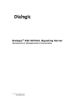


![121290 CR-4000 Controller User Manual [English].pub](http://vs1.manualzilla.com/store/data/005770288_1-ff1b31ed544f6d88740c7f5db9da46b2-150x150.png)