1
iUPS - Intelligent Uninterruptible Power Supply: User Manual
for the LAN Management
Abstract
This document describes the capabilities of the LAN Management
hardware and firmware.
Contents
1 Hardware
2
1.1
Communication interfaces . . . . . . . . . . . . . . . . . .
2
1.2
Battery connector . . . . . . . . . . . . . . . . . . . . . .
3
1.3
Binary inputs . . . . . . . . . . . . . . . . . . . . . . . . .
3
1.4
Binary outputs . . . . . . . . . . . . . . . . . . . . . . . .
3
1.5
Analog inputs . . . . . . . . . . . . . . . . . . . . . . . . .
3
1.6
Temperature sensor . . . . . . . . . . . . . . . . . . . . . .
3
1.7
Electrical characteristics . . . . . . . . . . . . . . . . . . .
4
2 Firmware
4
2.1
Configuration . . . . . . . . . . . . . . . . . . . . . . . . .
4
2.2
Watchdogs
. . . . . . . . . . . . . . . . . . . . . . . . . .
5
2.3
User scripts . . . . . . . . . . . . . . . . . . . . . . . . . .
6
2.4
User webpage . . . . . . . . . . . . . . . . . . . . . . . . .
8
2.5
Updating firmware and user files . . . . . . . . . . . . . .
11
3 Known bugs
12
1
Hardware
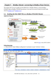
The LAN Management Unit is build as one PCB on which there are
external connectors and switches. Recommended connections of each
part are described in this section. The device PCB can be seen on the
Figure 1.
Figure 1: Hardware parts description.
1.1
Communication interfaces
Several interfaces are build in on this board.
1.1.1
Ethernet
There is Eth0 connector on the left side of PCB. This connector represents
standard 100/10 Mbit ethernet device which can be connected into a
standard IPv4 network. The web and the telnet interfaces are accessible
through this connector.
1.1.2
USB
The miniUSB connector is mounted on the left PCB side below Eth0.
This connector provides virtual COM port functionality.1 The communication baud rate, used in this interface, must be set to 9600 bps and
used command set is nearly same as the one used in the telnet.
1.1.3
I2C
The I2C connector is placed ad left-bottom part of the PCB. It si primary
used for a communication with other modules; therefore, the communication protocol is closed and isn’t described in this manual. The following
table describes the I2C connector pinout.
I2C connector pin description
Pin
1
2
3
4
5
1
2
Function
NC
NC
IRQ
SDA
SCL
Pin
10
9
8
7
6
Function
GND
For MS Windows the special driver is requested.
LAN Management User Manual
1.2
Battery connector
The battery connector, placed in the bottom-middle part of the PCB, is
designed to use with a battery calibration circuit. Therefore, it includes
seven GPIO pins and three ADC inputs. The GPIO pins function is not
implemented in fimware yet. On the other hand the ADC inputs can be
read by software. It can measure voltage in 0-5V range.
Battery connector pin description
Pin
1
3
5
7
9
11
13
15
17
19
1
1.3
Function
GPIO/SPI_CLK1
GPIO/SPI_CS11
GPIO/SPI_MISO1
GPIO/SPI_MOSI1
GPIO/Status21
GPIO/Status11
GPIO/Status01
ADC_IN_2
ADC_IN_1
ADC_IN_0
Pin
2
4
6
8
10
12
14
16
18
20
Function
GND
Not implemented in FW yet.
Binary inputs
The board contains 4 binary inputs insulated by optrons. They are placed
on the right side of PCB. For right function, the S-power connector have
to be connected to a voltage source with the voltage level range 5-48V
and the corresponding current limiting resistor have to be calculated and
connected. The values of the current limiting resistor can be calculated
as
R=
1.4
US−power − 1.2
[ohm]
0.005
(1)
Binary outputs
The board contains 4 binary outputs which are ended with mosfet transistors. They can be used to switching relays directly. The maximal
switching current can be 5A and maximal connected voltage can be 30V.
For the right function the voltage source have to be connected to the Repower connector. Notice that the GND pin is common with main power
source.
1.5
Analog inputs
The board contains 5 analog inputs scanned periodically by ADC. The
first three ADC inputs are connected to the battery connector as is described in ”Battery connector” section. Other two analog inputs are
wired to measure input voltage - the first for 3V3 branch and second for
24V branch.
1.6
Temperature sensor
The thermometer connector is placed on the top of the PCB. It is prepared to Dallas DS18B20 connection but it isn’t implemented in SW yet.
LAN Management User Manual
3
1.7
Electrical characteristics
Parameter
Min
Main power source
Source voltage
10V
Analog inputs
Input count
Max input voltage
Binary inputs
Input count
Max input voltage
Binary outputs
Output count
Max output voltage
3V
Forward current
-
2
2.1
Item
Typ Max
24V
30V
3
-
5V
4
-
30V
4
24V
5mA
30V
30mA
Firmware
Configuration
There are three sets of configuration in device.
Running configuration :
When user modifies any of the settings or port configuration, the
changes are saved inside running configuration. This configuration
is not permanent and is lost upon device restart. To keep running
configuration, it has to be saved to saved configuration.
Saved configuration :
This configuration is saved inside flash memory of processor and is
loaded to running configuration when the device starts.
Factory configuration :
The factory configuration is set from production and cannot be
modified by user. The only modification of factory config is possible
through firmware upgrade.
The running configuration can be saved through web interface. Futhermore, it is possible to restore device to factory configuration. The Fig.2
displays web interface for manipulating fir configurations.
4
LAN Management User Manual
Figure 2: Webpage for manipulating configurations.
2.2
Watchdogs
The system allows its user to monitor devices through the watchdogs.
Up to 12 watchdogs can be defined, one for each port. Watchdog configuration consists of the following elements:
Target IP address :
Type of connection :
The IP address that is to be monitored.
Watchdogs can utilize one of three protocols to monitor the device:
ICMP
TCP
UDP
Connection port :
Actions on failure :
If the TCP or UPD protocol is selected, user has to specify target
port.
User may specify one or more action on failure.
Restart device
Send email
Run script - runs the function that user specifies
LAN Management User Manual
5
Figure 3: Webpage for configuring watchdogs.
2.3
User scripts
User script file is saved in the reserved part of flash memory inside processor. The size of this reserved block is 16kB. Consequently, the size of
supplied script can be up to 16kB-4B used to store script size.
User script can be written in ANSI C language with limited macro and
standard library support. Furthermore, to access non-standard device
functions, it is required to include the stk.h header file.
! → The main function has to be always defined, even if the user is not using
the scripting system.
2.3.1
Function set
void portOn(int)
Description :
This function powers up specified port (in case associated module is
connected). Ports status is also modified in running configuration.
Parameters :
port number
Return value :
Returns nothing.
void portOff(int)
Description :
This function powers off specified port (in case associated module is
connected). Ports status is also modified in running configuration.
Parameters :
port number
Return value :
Returns nothing.
unsigned char portStatus(int)
Description :
! →
Parameters :
Return value :
6
This function returns power status of specified port.
The port status is determined from the running configuration, not
by querying module.
port number
Returns 0 or 1 depending on power status of port.
LAN Management User Manual
void signalBinSet(unsigned int, unsigned int)
Description :
Sets the value of the specified binary output.
Parameters :
number of binary output in range (0 - 3)
requested value in range (0 - 1)
Return value :
Returns nothing.
unsigned int signalBinGet(unsigned int)
Description :
Returns the value of the specified binary input.
Parameters :
number of binary input in range (0 - 3)
Return value :
Returns 0 or 1 depending on status of input.
double signalAnaGet(unsigned int)
Description :
Returns the value of the specified analog input.
Parameters :
number of analog input in range (0 - 4)
Return value :
Returns analog value of the specified analog input.
unsigned int currentTimeMs()
Description :
Returns current time from the start of the device in milliseconds.
Parameters :
none
Return value :
Current time in milliseconds.
void sendMail(char *, char *)
Description :
Sends email to the address specified in settings.
Parameters :
Email subject
Email text
Return value :
2.3.2
none
Script examples
Script for controlling binary outputs with the aid of timer
#include <stk.h>
#include <stdio.h>
void main(void)
{
unsigned int time_seconds = currentTimeMs() / 1000;
if(time_seconds % 20 < 10) {
#Set binary_output_0 to 1 and binary_output_1 to 0
signalBinSet(0, 1);
signalBinSet(1, 0);
} else {
#Set binary_output_0 to 0 and binary_output_1 to 1
signalBinSet(0, 0);
signalBinSet(1, 1);
}
}
LAN Management User Manual
7
Script for watching analog inputs and sending warning through
email if one of the input value exceeds specified threshold
#include <stk.h>
#include <stdio.h>
#define THRESHOLD
3.3
#define TIME_BETWEEN_MAILS 60000
unsigned int time_guard = 0;
void main(void)
{
unsigned char i;
for(i = 0; i < 5; i++) {
if(signalAnaGet(i) > THRESHOLD) {
if(time_guard < currentTimeMs()) {
sendMail("Threshold exceeded",
"One of the analog inputs exceeded specified threshold");
time_guard = currentTimeMs() + TIME_BETWEEN_MAILS;
}
}
}
}
Script that powers up binary output if one or more binary inputs are at 0
#include <stk.h>
#include <stdio.h>
void main(void)
{
unsigned char num_of_off_inputs = 0;
unsigned char i;
for(i = 0; i < 4; i++) {
if(signalBinGet(i) == 0) {
num_of_off_inputs++;
}
}
if(num_of_off_inputs > 0) {
signalBinSet(0, 1);
}
}
2.4
User webpage
To allow users to tailor device to their requirements, the device contains
user changeable webpage. Similarly to user script file, the webpage file
is timited to size 16kB - 4B. The webpage can use both SSI and CGI
features of the embedded webserver to deliver dynamic webpages.
8
LAN Management User Manual
2.4.1
SSI
The SSI2 is a way to include dynamic information inside webpage during
its composition. The SSI is used in form of so-called tags, which are
replaced by the requested information. The number of tags inside page
is not limited.
The tags are used as <!--#TagName--> inside the code of webpage.
Table of tags and dynamic content they represent
Tag
IPAddress
Netmask
Gateway
MACAddress
PanelName
SMTPServer
SMTPOutMail
SMTPRecMail
SignalBinIn1
SignalBinIn2
SignalBinIn3
SignalBinIn4
SignalAnaIn1
SignalAnaIn2
SignalAnaIn3
SignalAnaIn4
SignalAnaIn5
2.4.2
Content
The devices IP address
The devices Network mask
The devices Gateway
The devices MAC address
Device name
The address of SMTP server
Source mail address
Target mail address
The value of binary input 1
The value of binary input 2
The value of binary input 3
The value of binary input 4
The value of analog input 1
The value of analog input 2
The value of analog input 3
The value of analog input 4
The value of analog input 5
CGI
The CGI3 can be used to send information to device. For example, if the
user requests url 192.168.0.1/signals.cgi?SigBinOut1=1, the device
sets SigBinOut1 to 1. The following table displays complete set of user
CGI requests. It is possible to set multiple signals through one request.
function setOutputState(port, value)
{
var xmlhttp;
xmlhttp=new XMLHttpRequest();
var request = "signals.cgi?BinOut" + port + "=" + value;
xmlhttp.open("GET", request, true);
xmlhttp.send();
}
Figure 4: Javascript code for utilizing CGI.
Table of CGI requests and associated action
2
3
LAN Management User Manual
Server Side Includes
Common Gateway Interface
9
Request
signals.cgi?BinOut1=0
signals.cgi?BinOut1=1
signals.cgi?BinOut2=0
signals.cgi?BinOut2=1
signals.cgi?BinOut3=0
signals.cgi?BinOut3=1
signals.cgi?BinOut4=0
signals.cgi?BinOut4=1
10
Action
Sets SigBinOut1
Sets SigBinOut1
Sets SigBinOut2
Sets SigBinOut2
Sets SigBinOut3
Sets SigBinOut3
Sets SigBinOut4
Sets SigBinOut4
to
to
to
to
to
to
to
to
0
1
0
1
0
1
0
1
LAN Management User Manual
2.4.3
Example webpage
<!DOCTYPE html>
<html>
<head>
<meta charset="UTF-8">
<title>Web management</title>
<link rel="stylesheet" href="styl.css" media="all" type="text/css" />
</head>
<body>
<h1>User webpage</h1>
<br>
<br>
<h2>Analog inputs</h2><br>
Input 1: <!--#SignalAnaIn1--> V<br>
Input 2: <!--#SignalAnaIn2--> V<br>
Input 3: <!--#SignalAnaIn3--> V<br>
Input 4: <!--#SignalAnaIn4--> V<br>
Input 5: <!--#SignalAnaIn5--> V<br>
<br>
<br>
<h2>Binary inputs</h2><br>
Input 1: <!--#SignalBinIn1--><br>
Input 2: <!--#SignalBinIn2--><br>
Input 3: <!--#SignalBinIn3--><br>
Input 4: <!--#SignalBinIn4--><br>
<br>
<br>
</body>
</html>
2.5
Updating firmware and user files
The firmware and user files can be updated after jumping to bootloader.
As can be seen on Fig. 5 the bootloader can be opened from the web
interface.
The process of uploading firmware has been tested in Internet Explorer,
other browsers were not fully tested. The process does not work currently
in Opera browser.
! → The firmware upgrade may invalidate existing saved configuration, at
which point, the factory configuration is used.
LAN Management User Manual
11
Figure 5: Menu item for entering bootloader.
3
Known bugs
1. The bootloader does not work properly in Opera browser.
2. The status leds are currently used for informing user about connected modules.
3. SNTP module for retrieving current date and time is not completely
implemented and tested.
12
LAN Management User Manual