1
User Manual
Product Descriptions:
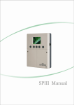
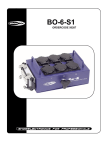
This is a versatile 32A three-phase, 4-way motor commander with a choice of either one ILME
socket or 4 CEE sockets for output loading. The Forward, Backward Rotation and Idle modes
are available by flipping the universal changover switch. And the emergency stop of the motor
is available by pushing the push button switch under the fault condition. Furthermore, one 32 A
residential circuit breaker and one 2 Amp MCB are be used for protection when a fault condition
or voltage spike. Also, a CEE-plug is provided for plugging in power. 19" rack mount/4U front
panel profile design gives you peace of mind. Please read carefully this instruction and printings
on the case of this product before operation.
Technical Details:
Coating:
Input:
Output:
Motor control:
RUN/STOP control:
Mounting:
Net Weight:
Coated with blue epoxy powder paint
AC230V~3Phase 32A/Phase
4x CEE sockets & 1xILME socket
4 Universal Changeover Switches
2 Push Button Switches
19" rack mount/4U
Approx 7.0 Kg
Operating Instructions:
Forward Rotation Mode
When powering on, select the desired motor, and flip its universal changeover switch to the "UP"
position to access to the Forward Rotation Mode, then press the "RUN" push button to run forward.
Backward Rotation Mode
When powering on, select the desired motor, and flip its universal changeover switch to the
"DOWN" position to access to the Backward Rotation Mode, then press the "RUN" push button
to run backward.
24-004-1773
Rev1.0
Idle Mode
When powering on, select the desired motor, and flip its universal changeover switch to the "0"
position to access to the Idle Mode, all four outputs are isolated and any operations are void.
Emergency Stop Mode
When powering on, user can press the "STOP" push button to stop emergently under any fault
operation condition.
WARNING!
-The ground connection should be so essential!
-Risk of electric shock, disconnect input power before opening.
-To prevent fire or electric shock, do not expose this apparatus under a high temperature or
moisture area.
-Specifications and improvements in the design and this manual of this product are subject to
changes without any prior written notice.
Appendix i:ILME Pin Assignment and Connector Motors
16-pin ILME socket(x1pcs)
MOTOR 1
Pin
Pin
MOTOR 2
Pin
MOTOR 3
MOTOR 4
Pin
1
L1
5
L1
9
L1
13
L1
2
L2
6
L2
10
L2
14
L2
3
L3
7
L3
11
L3
15
L3
4
8
12
16
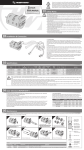
Appendix ii:Interior Connection Diagram