1
CS-Manager
User's Manual
G. Jost - Electronic, 12.05.07
Version 1.3
CRM-2010
Table of Contents
1 Introduction...................................................................................................................................... 1
1.1 Overview....................................................................................................................................1
1.2 Typographical Conventions....................................................................................................... 1
2 Architecture of CS-Manager..............................................................................................................2
2.1 Overview....................................................................................................................................2
2.2 Software Architecture................................................................................................................ 2
2.3 The CRM-2010 as a USB drive................................................................................................. 3
2.4 File Formats of Data Exchange Files.........................................................................................3
2.4.1 Overview............................................................................................................................ 3
2.4.2 Format of Measurement Data Files.................................................................................... 3
2.4.3 Format of Battery Definition Files..................................................................................... 4
2.5 Restrictions................................................................................................................................ 4
2.5.1 Supported Platforms...........................................................................................................4
2.5.2 Capacity Limits.................................................................................................................. 5
3 Installation of CS-Manager................................................................................................................6
3.1 Overview....................................................................................................................................6
3.2 Installation................................................................................................................................. 6
3.3 Configuration........................................................................................................................... 11
4 The First Steps................................................................................................................................. 14
4.1 Overview..................................................................................................................................14
4.2 Notions and Objects.................................................................................................................14
4.2.1 Overview.......................................................................................................................... 14
4.2.2 Profile...............................................................................................................................14
4.2.3 Navigation Tree................................................................................................................14
4.2.4 Tree Node.........................................................................................................................14
4.2.5 Root.................................................................................................................................. 14
4.2.6 Child node........................................................................................................................ 15
4.2.7 Area.................................................................................................................................. 15
4.2.8 Area ID............................................................................................................................. 15
4.2.9 Block Type....................................................................................................................... 15
4.2.10 Battery............................................................................................................................ 15
4.2.11 Battery ID....................................................................................................................... 15
4.2.12 Measurement Parameters............................................................................................... 15
4.2.13 Measurement Type “Tour“.............................................................................................16
4.2.14 Measurement Type “Test“............................................................................................. 16
4.2.15 Analysis Type “Trend“...................................................................................................16
4.2.16 Analysis Type “Comparison“.........................................................................................16
4.2.17 Preview of Measurement Data....................................................................................... 16
4.3 The Basic Workflow................................................................................................................ 17
4.3.1 Overview.......................................................................................................................... 17
4.3.2 Define Areas.....................................................................................................................18
4.3.3 Define Block Types..........................................................................................................20
4.3.4 Define Batteries................................................................................................................21
i
4.3.5 Connect the Device.......................................................................................................... 22
4.3.6 Upload Battery Definitions.............................................................................................. 24
4.3.7 Download Measurement Data..........................................................................................26
4.3.8 Associate Unassociated Areas and Batteries....................................................................28
4.4 The CS Manager Browser........................................................................................................29
4.4.1 Overview.......................................................................................................................... 29
4.4.2 Navigation........................................................................................................................ 30
4.4.3 Maintain Data...................................................................................................................32
4.4.4 Preview Measurement...................................................................................................... 33
4.4.5 Analysis of Measurement Data........................................................................................ 34
4.4.5.1 Overview.................................................................................................................. 34
4.4.5.2 Trend........................................................................................................................ 35
4.4.5.3 Comparison.............................................................................................................. 36
5 Data Maintainance........................................................................................................................... 40
5.1 Overview..................................................................................................................................40
5.2 Maintain Area Data..................................................................................................................40
5.2.1 Overview.......................................................................................................................... 40
5.2.2 Create New Area.............................................................................................................. 40
5.2.3 Change an Existing Area..................................................................................................42
5.2.4 Delete an Area..................................................................................................................42
5.3 Maintain Block Type Data.......................................................................................................42
5.3.1 Overview.......................................................................................................................... 42
5.3.2 Create New Block Type................................................................................................... 42
5.3.3 Change an Existing Block Type.......................................................................................44
5.3.4 Delete an Block Type....................................................................................................... 44
5.4 Maintain Battery Data..............................................................................................................45
5.4.1 Overview.......................................................................................................................... 45
5.4.2 Create New Battery.......................................................................................................... 45
5.4.3 Change an Existing Battery..............................................................................................47
5.4.4 Delete an Battery.............................................................................................................. 47
6 Data Analysis...................................................................................................................................48
6.1 Overview..................................................................................................................................48
6.2 Print or Export Main Data....................................................................................................... 48
6.3 Analysis of Measurement Data................................................................................................ 49
6.3.1 Overview.......................................................................................................................... 49
6.3.2 Trend Analysis................................................................................................................. 49
6.3.2.1 Overview.................................................................................................................. 49
6.3.2.2 Trend Table.............................................................................................................. 49
6.3.2.3 Start Trend Diagram................................................................................................. 51
6.3.2.4 Print or Export Trend Diagram............................................................................... 52
6.3.3 Comparison...................................................................................................................... 52
6.3.3.1 Overview.................................................................................................................. 52
6.3.3.2 Comparison Table.................................................................................................... 53
6.3.3.3 Comparison Diagram............................................................................................... 54
6.3.3.4 Print or Export Comparison..................................................................................... 56
ii
7 Appendix......................................................................................................................................... 57
7.1 Release Notes...........................................................................................................................57
7.1.1 Version 1.2....................................................................................................................... 57
7.2 Future Development................................................................................................................ 57
8 References....................................................................................................................................... 58
iii
List of Figures
Figure 1: Battery Definition File.......................................................................................................... 3
Figure 2: Battery Definition File (truncated at Cell No 2).................................................................. 4
Figure 3: Start of Installation Tool....................................................................................................... 6
Figure 4: Defining the Target Directory............................................................................................... 7
Figure 5: Start the Installation Process................................................................................................. 8
Figure 6: Installation succeeded.......................................................................................................... 9
Figure 7: Directory Structure used by CS-Manager........................................................................... 10
Figure 8: System Menu.......................................................................................................................11
Figure 9: System Menu.......................................................................................................................12
Figure 10: System Data...................................................................................................................... 13
Figure 11: Add new area.....................................................................................................................18
Figure 12: Area Data.......................................................................................................................... 19
Figure 13: New Block Type................................................................................................................20
Figure 14: Create new battery.............................................................................................................21
Figure 15: Battery Data.......................................................................................................................22
Figure 16: Start Export Battery Definitions........................................................................................24
Figure 17: Export Battery Definitions................................................................................................ 25
Figure 18: Start Import Measurement Data........................................................................................ 26
Figure 19: Import Measurement Data.................................................................................................27
Figure 20: Unknown Areas.................................................................................................................28
Figure 21: Different Areas in CS-Manager........................................................................................ 29
Figure 22: Initial Tree State................................................................................................................ 30
Figure 23: Partially unfolded tree....................................................................................................... 31
Figure 24: Area Data.......................................................................................................................... 32
Figure 25: Preview of Measurement Data.......................................................................................... 33
Figure 26: Analysis Modes................................................................................................................. 34
Figure 27: Start Analysis "Trend"...................................................................................................... 35
Figure 28: Trend Diagram.................................................................................................................. 36
Figure 29: Start Analysis "Comparison"............................................................................................ 37
Figure 30: Comparison (one measurement selected)..........................................................................38
Figure 31: Comparison (two measurements selected)........................................................................39
Figure 32: Attributes of AREA.......................................................................................................... 41
Figure 33: Create Area........................................................................................................................41
Figure 34: New Block Type................................................................................................................43
Figure 35: Attributes of BLOCK TYPE............................................................................................. 44
Figure 36: New Battery Data.............................................................................................................. 45
Figure 37: Attributes of BATTERY................................................................................................... 46
Figure 38: Export or Print Data.......................................................................................................... 48
Figure 39: Start Trend Table............................................................................................................. 50
Figure 40: Trend Table....................................................................................................................... 50
Figure 41: Start Trend Diagram..........................................................................................................51
Figure 42: Trend Diagram.................................................................................................................. 52
Figure 43: Start Comparison Table.................................................................................................... 53
iv
Figure 44: Comparison Table (defective battery)..............................................................................54
Figure 45: Comparison Diagram: One Tour.......................................................................................55
Figure 46: Comparison Diagram: Two Tours.................................................................................... 55
Figure 47: Clear Graphics Window....................................................................................................56
v
1 Introduction
1 Introduction
1.1 Overview
CS-Manager is a software which allows to maintain measurement data of batteries. The
measurement data are obtained from our new Cellizer Measurement Systems, CRM-2010, CS-4001
and CM-9010. The software allows:
●
●
●
●
●
Maintenance of area data
Maintenance of block type data
upload of battery definition data to the measurement systems
Download of the measurement data from the CRM-2010
Analysis of Measurement Data
This document describes the installation of the software, the maintenance and analysis of data.
1.2 Typographical Conventions
Objects belonging to the system environment (a path within the computer's file system, a program
name) are printed in courier font face. A definition is printed in italic.
Page 1
2 Architecture of CS-Manager
2 Architecture of CS-Manager
2.1 Overview
The following sections describe aspects of the architecture of CS-Manager, e.g.
●
Software Architecture
●
The CRM-2010 as a USB drive
●
Format of Measurement Data Files
●
Format of Battery Definition Files
●
Restrictions
Not described are the architecture or concepts of the CRM-2010 device or CS-4001(see [1] and [2]).
2.2 Software Architecture
The internal architecture of CS-Manager follows a classical two-tier-System (Fat Client). The
backend where data are stored is a database. Currently only a built-in database is supported. Future
releases will support arbitrary relational database systems (RDBMS) which will allow the user to do
individual data processing on the measurement data collected be the CRM-2010 or data warehouse
business.
Measurement data downloaded from the CRM-2010 is not only stored in the database. In additions
the data file is stored in a history directory. In case the database is damaged by external processes or
“accidents“ this allows a disaster recovery.
The Software does not register itself in the Windows registry. This might seam a bit unusual. The
reason which CS-Manager has been implemented that way is to make it as robust as possible. It is
possible to move the directory which contains the CS-Manager Software and its configuration files
without changing special configuration parameters manually or even affect the integrity of data.
When CS-Manager is installed the software and its configuration and database will be installed in
a directory by default. The location of the database or the history directory can be changed
arbitrarily. A form in CS-Manager allows to change the affected system parameters at any point in
time. So it is impossible to “move“ the application or only its database when the file system is full.
Page 2
2 Architecture of CS-Manager
2.3 The CRM-2010 as a USB drive
From the perspective of CS-Manager the CRM-2010 device is “just“ a removable device. In the
system data of CS-Manager the name of the volume associated with the CRM-2010 is configured.
This allows to implement easy and straight-forward data exchange mechanisms. When the user tries
either to download measurement data or to upload CS-Manager first locates the volume associated
with the CRM-2010 device. If this fails the user cannot initiate a data transfer operation. If the
volume is found the exchange file is copied to or from the device depending on the operation.
If measurement data are downloaded from the CRM-2010 the data is checked whether or not it has
been already downloaded. If not, the data file is copied into CS-Manager's history directory and is
imported in the database. Duplicate imports cannot take place.
2.4 File Formats of Data Exchange Files
2.4.1
Overview
If the Software CS-Manager and the CRM-2010 device exchange data they use special files for that.
If battery definitions should be uploaded to the CRM-2010 a file is copied into the CRM-2010's file
system.
If measurement data should be transferred from the device into the database a file generated on the
CRM-2010 is copied to the CS-Manager history directory. The content of this file is imported into
the database.
The files types are comma separated values (CSV) and can be viewed with Microsoft Excel or any
other spreadsheet program. Both file types contain header information and a data section. Its values
are separated with semicolons.
The formats of these files are described in the next sections by giving an example.
2.4.2
Format of Measurement Data Files
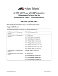
The following table shows an example Battery definition file:
Battery Data for CS-4001
MEMO
MEMO
Batt_Name Area_Name Battery_ID Area_ID No. Of Cells UCELL min [V] UCELL max [V] UBATT min [V] UBATTmax [V] Shunt [A] Shunt [mV] Capacity [Ah] Discharge Current Discharge Time
{
<
<
<
<
<
TestGJ1
TestGJ2
TestGJ2b
TestGJ3
TestGJ4
GJ_Area1
GJ_Area2
GJ_Area2b
GJ_Area3
GJ_Area4
1
12
12
123
1234
5
56
56
567
5678
32
64
64
96
127
2
2
2
12
12
1
2
2
1
2
2
2
2
13
13
7
8
8
1
2
60
70
70
200
230
80
90
90
280
290
100
200
200
1000
2000
60
60
60
1000
1000
10
100
100
1000
9999
100
1>
200
2>
200
5>
300
3>
9 400 >
Figure 1: Battery Definition File
Page 3
2 Architecture of CS-Manager
2.4.3
Format of Battery Definition Files
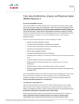
The following table shows an example of a measurement file. The last line contains the
measurement data. In the example the battery consists of 14 cells. The display of the voltage values
is truncated a cell number 2.
SYSTEM:
SN:
CALIBRATED:
SOFTWARE:
PRODUCER:
CS-4001/127
V01.0
4001001
26/01/06
CS-4001/127
G. JOST - ELECTRONIC
BATT-ID:
BATT-NAME:
AREA-ID:
AREA-NAME:
CELLS:
CAPACITY [Ah]:
CELL LIMIT MIN [V]:
CELL LIMIT MAX [V]:
BATT LIMIT MIN [V]:
BATT LIMIT MAX [V]:
SHUNT DEF. A:
SHUNT DEF. MV:
V01.0
GERMANY [email protected]
12
34
14
100
1
2
15
24
100
10
FUNCTION:
TEST DATE:
TEST TIME:
TOUR
Time
UBatt [V]
0
400
345
67
56
17/04/06
14:43:38
00:00:00
I [A]
19
CBatt [Ah]
57
TBatt [°C] CELL-1 [V] CELL-2 [V]
673
4
0
0
Figure 2: Battery Definition File (truncated at Cell No 2)
2.5 Restrictions
2.5.1
Supported Platforms
CS-Manager has successfully been tested on the following Systems:
●
Windows 2000
●
Windows XP
●
Windows Server 2000
●
Windows Server 2003
Page 4
2 Architecture of CS-Manager
2.5.2
Capacity Limits
CS-Manager uses a built-in database system which allows “only“ to store an amount of data of 4
Gigabyte. If another RDMBS is used CS-Manager theoretically has got no capacity limits. Other
RDMBS will be supported in future.
Page 5
3 Installation of CS-Manager
3 Installation of CS-Manager
3.1 Overview
The installation of CS-Manager will be conducted by a setup program. After the installation CSManager is ready to use. At the first start it creates an empty database which is used for operation
from that point in time.
After the installation a default configuration is used. If this should be changed – for example the
database or history directory should renamed – this can be achieved with a CS-Manager's form.
3.2 Installation
To install CS-Manager the program Setup.exe should be invoked. The installation process will
be conducted by the setup tool. The installation process can be aborted by pressing the button
“Cancel“ at any stage of the installation process. When the installation tool has been started the
following form is displayed:
Figure 3: Start of Installation Tool
Page 6
3 Installation of CS-Manager
Pressing the button “Next“ leads to the following form, where the target directory can be defined.
The default directory is c:\Program Files\Cellizer\CS-Manager:
Figure 4: Defining the Target Directory
The administrator can decide whether or not CS-Manager should be available for every user on the
workstation. This can be achieved by selecting the appropriate radio buttons “Everyone“ or “Just
me“. The amount of disk space required for the installation can be checked by pressing the button
“Disk Cost ...“.
If the button “Browse“ is pressed the target directory can be changed.
Page 7
3 Installation of CS-Manager
Pressing the button “Next“ allows to start the installation process:
Figure 5: Start the Installation Process
If you are not sure you can either go back by pressing “Back“ or quit the installation completely by
pressing the button “Cancel“.
Page 8
3 Installation of CS-Manager
If the installation process succeeds the following form is displayed:
Figure 6: Installation succeeded
Now the Software has been installed in the directory
C:\Program Files\Cellizer\CS-Manager.
Page 9
3 Installation of CS-Manager
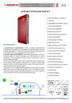
The Software, its configuration data and the database has been installed in this directory. The next
figure shows the subdirectories created by the installation tool:
Figure 7: Directory Structure used by CS-Manager
Usage of subdirectories:
Directory
bin
Used for
Contains the program CS-Manager.exe
data
Contains the database
etc
Contains the configuration and profile files
history
Measurement data imported from the CRM-2010 are stored here
tmp
Used for temporary data
updates
Program Updates will be stored here (future releases will support that)
Page 10
3 Installation of CS-Manager
3.3 Configuration
If CS-Manager started for the first time the database is empty and profiles are not configured. CSManager asks the user whether or not a default profile should be created. If the users presses the
button “Yes“ a default profile is created and CS-Manager starts. To change the system parameters of
CS-Manager the menu “System“ has to be invoked:
Figure 8: System Menu
Next the user should select the menu item “System Parameters“. If this menu item is selected the
following form displays global parameters of CS-Managers which can be changed:
Page 11
3 Installation of CS-Manager
Figure 9: System Menu
Currently only the parameters “Temperature“, ”Database Name“ and “Volume Name“ can be
changed. Future releases will support different profiles with different languages. If the button “Save
is pressed the changes are stored. These changes will affect CS-Manager only if the program is restarted.
Page 12
3 Installation of CS-Manager
Figure 10: System Data
Currently only the parameters „Temperature“, „Database Name“ and „Volume Name“ can be
changed. Future releases will support different profiles with different languages. If the button „Save
is pressed the changes are stored. These changes will affect CS-Manager only if the program is restarted.
Page 13
4 The First Steps
4 The First Steps
4.1 Overview
Before the CS-Manager software can be used some preparations have to be done. Notions and
objects used in CS-Manager are introduced in section 4.2. How to use CS-Manager is described in
section 4.4. To download the measurement data the steps described in section 4.3 have to be done.
4.2 Notions and Objects
4.2.1
Overview
The following sections describe notions and objects used in CS-Manager.
4.2.2
Profile
A profile is a set of parameter settings, for example language, database, etc. Profiles can be used to
set up CS-Manager for different clients. If a user works for different customers he can associate
different profiles with the customers. As a result, each customer gets his own database.
4.2.3
Navigation Tree
The navigation tree is a user interface component and defines the hierarchy between areas, batteries
and measurement data. By clicking its entries the user can navigate within this hierarchy. The
associated data is displayed in a different form.
4.2.4
Tree Node
A tree node is an entry in the tree used for navigation.
4.2.5
Root
The root is the topmost node of a (sub-)tree.
Page 14
4 The First Steps
4.2.6
Child node
A child node is a tree node connected to another tree node.
4.2.7
Area
An area is a location where the batteries are situated. An area can be a building, a room, etc.
4.2.8
Area ID
An area ID is a unique identifier (numbers from 1 ... 1000000) for an area used in a profile.
4.2.9
Block Type
A block type defines the characteristics of a battery. Every battery has to be associated with a block
type.
4.2.10
Battery
A battery consisting of cells is the object from which the measurement data are obtained. Every
battery has to be located in an area.
4.2.11
Battery ID
A battery ID is a unqiue identifier (numbers from 1 ... 1000000) for batteries in an area. Batteries in
different areas may have the same battery ID.
4.2.12
Measurement Parameters
Measurement parameters supported by the CRM-2010 are
●
block voltage
●
block resistance
●
battery capacity (CS-4001)
●
battery temperature
Page 15
4 The First Steps
4.2.13
Measurement Type “Tour“
In a tour the voltage values for all cells of a battery at a certain point in time are retrieved. A
collection of tours of a certain battery is called “history“.
4.2.14
Measurement Type “Test“
A capacity test retrieves cell voltage values of a battery periodically. The length of the test interval
defines the amount of data.
4.2.15
Analysis Type “Trend“
A trend visualises the history (collection of tour data) of a battery or a cell. A trend can be displayed
either as a table or as a diagram.
4.2.16
Analysis Type “Comparison“
A comparison allows to compare measurements of the same type (tour or capacity test) of different
batteries.
4.2.17
Preview of Measurement Data
A preview consists of a small diagram and a form containing important parameters of a
measurement.
Page 16
4 The First Steps
4.3 The Basic Workflow
4.3.1
Overview
When CS-Manager is used for the first time it does not contain any data. Measurement data can be
downloaded from the CRM-2010, but how do battery and area information get into the device? And
where do the data come from?
Areas, batteries, block types, etc. have got a certain relationship. This relationship defines in what
sequence data should be processed.
Because batteries are situated in areas everything begins with defining the required areas. Before a
battery is created and associated with one of the areas the user should make sure that the block types
which should be used are defined. After that the batteries are created and associated with the areas.
Before the user does the actual measurement the information about areas and batteries have to be
transferred to the measurement device (upload battery definitions). Now everything is ready to do
the actual measurement. When this has been finished, die measurement data can be downloaded
from the device and are imported into CS-Manager's database. The basic workflow
1. Define Areas
2. Define Block Types
3. Define Batteries
4. Upload Battery definitions
5. Do the measurement tasks
6. Download measurement data
is described in the sections to 4.3.7.
But what happens if the user forgets one of the steps or he takes a different CRM device which does
contain area and battery definitions not stored in his CS-Manager version? Will the measurement
data captured with this device be useless?
Of course, the answer is no. CS-Manager imports measurement data even if the ”come from the
wrong areas“. The data are imported and kept as ”Unknown Objects“. The user can define areas,
battery definitions, etc. after the import and re-associate the batteries manually (see section ).
Page 17
4 The First Steps
4.3.2
Define Areas
To define a new area the node ”Area Data“ has to be selected. After pressing the button “New Area“
a form is displayed allowing to enter the area parameters (see figure 10).
Figure 11: Add new area
Page 18
4 The First Steps
Figure 12: Area Data
The area ID has to be unique within the database. Therefore, the system suggests an area ID which
can be changed manually. After the data have been entered they can be written into the database by
pressing the button “Save“.
Page 19
4 The First Steps
4.3.3
Define Block Types
Before a battery can be associated with an area it has to be ensured that the required block type is
defined. To create a new block type record the node “Block Types“ in the tree should be selected. If
the button “New Block Type“ is pressed a form is displayed allowing to enter the block type's
parameters (see figure 11).
First manufacturer, block type and battery design (Pb, NiCd, etc.) should be entered. In the next
section on the form minimum and maximum values can be entered, either as absolute or relative
values. These values are considered in the analysis processes. For example, the minimum voltage is
displayed as a red line in the diagram, values less than the minimum voltage are marked red in a
table, etc.
The last section contains parameters only relevant in the context of capacity tests. If the current
record should be written into the database, the user should press the button “Save“.
Figure 13: New Block Type
Page 20
4 The First Steps
4.3.4
Define Batteries
When areas and block types are defined battery records can be created. This can be achieved by
selecting the area in which the battery is located.
Figure 14: Create new battery
By pressing the button “New Battery“ a form is opened see figure 13).
Page 21
4 The First Steps
Figure 15: Battery Data
CS-Manager suggests a battery ID because this ID has to be unique within this area. The battery ID
can be changed manually. In this case the user has to ensure that the battery ID is unique.
When the parameters have been entered the battery record can be saved by pressing the button
“Save“.
4.3.5
Connect the Device
The measurement device (CRM-2010) now can be connected to the computer using an USB cable.
If the device is powered on it will be recognised as a mass storage system and appear as a “normal“
volume in the explorer. The measurement files on the CRM-2010 are CSV files.
If the device is not displayed in the explorer of the Windows system please check whether or not
the cable is properly connected and the device is switched on.
Page 22
4 The First Steps
4.3.6
Upload Battery Definitions
If new areas or batteries are defined since the last measurement download the new battery
definitions should be uploaded to the CRM-2010. The appropriate menu entry is part of the
pulldown menu “System“:
Figure 16: Start Export Battery Definitions
When the entry is selected a form is displayed which allows to define which areas and which
batteries should be uploaded (see figure 17). The leftmost list contains the available areas. If an
entry is selected the associated batteries will appear in the list in the middle. The rightmost list
indicates the list of batteries to be uploaded to the device. This list acts as a container which can be
filled by selecting batteries from the list in the middle and „moving“ the selected entries with the
buttons “>“ or “>>“. The button „>“ picks only the selected batteries. With “>>“ all batteries
displayed are selected even if they are not highlight.
Items can be remove from the list using the buttons “<“ (remove selected items) and “<<“ (remove
all items).
Page 23
4 The First Steps
To make life a bit easier “Select All“ buttons are available for every column. Before the collection
of batteries is transferred to the device the choice should be saved first with the button “Save
Settings“. When this has been done the actual data transfer can be initiated by pressing the button
“Export Battery Definitions“.
Note: The CRM-2010 has to be set into the correct mode before starting the data transfer (please
refer to the manual of the measurement device).
Figure 17: Export Battery Definitions
Page 24
4 The First Steps
4.3.7
Download Measurement Data
When the measurements are done the data should be imported into CS-Manager. To to this the
pulldown menu “Import Measurement Data“ has to be used:
Figure 18: Start Import Measurement Data
When the menu entry is selected the following form is displayed (see figure 19). If the button
”Import Measurement Data“ is pressed the measurement data is imported into the database.
Note: The CRM-2010 has to be set into the correct mode before starting the data transfer (please
refer to the manual of the measurement device).
Page 25
4 The First Steps
Figure 19: Import Measurement Data
During the import process CS-Manager checks whether or not a measurement has already been
imported and denies multiple imports. If the import has finished the data can be used immediately
for analysis purposes.
Page 26
4 The First Steps
4.3.8
Associate Unassociated Areas and Batteries
What happens if measurement data are imported of batteries and areas which are not stored in the
database? This might happen for example if the user picks a “wrong“ measurement device which
has been configured for different client. Actually, this is not a problem. The records will be
imported and indicated as “Unknown Objects“. If an area ID occurs which is not stored in the
database an appropriate record will be generated and displayed in the subtree “Unknown Areas“.
Analogously, unknown batteries appear at “Unknown batteries“. The user may change these records
manually so that these areas and batteries are “correctly“ put into the database.
Figure 20: Unknown Areas
Page 27
4 The First Steps
4.4 The CS Manager Browser
4.4.1
Overview
The following sections describe the handling and concepts of CS-Manager briefly. CS-Manager is a
tree navigator which visualises the associations between areas, batteries and measurement data.
Figure 21 shows the different areas of CS-Manager:
Figure 21: Different Areas in CS-Manager
The left side is the navigation area. The first entry in the tree is associated with the block types
defined for the current profiles. Areas used in the current profile area added below the tree node
“Area Data“. If a battery is situated in an area its representing tree node is put below the area node.
As expected, associated measurement data are put below the appropriate battery node.
The node “Undefined Objects“ has got two child nodes:
●
Undefined Areas
●
Undefined Batteries
If measurement data are downloaded from the CRM-2010 and an area ID is used which is not stored
in the database an appropriate entry is made in “Undefined Areas“. Similarly unknown battery IDs
are treated and appended to the node “Unassociated Batteries“.
Page 28
4 The First Steps
4.4.2
Navigation
The tree in the left window area is used to navigate through the database. When CS-Manager is
started only the nodes
●
Block Types
●
Area Data
●
Unknown Objects
are displayed:
Figure 22: Initial Tree State
The node currently selected in the tree is high-lighted (here Block Types). A node can be selected by
clicking with the mouse on it or using the cursor keys “up“ and “down“. A “+“ sign in front of a tree
node indicates that this node has got child nodes. For example, if an area node is shown with a “+“
batteries are associated with this area.
Page 29
4 The First Steps
When a node with a leading “+“ is high-lighted the subtree can be unfolded either by clicking with
the mouse on the „+“ or by pressing the cursor key “right“. When a subtree is unfolded a leading “-“
is displayed.
To collapse the subtree the user either can click on “-“ or use the cursor key “left“.
Figure 23 shows a partially expanded tree:
Figure 23: Partially expanded tree
Whenever the user selects a node within the tree on the right side an appropriate form is displayed.
Because the root of the subtree “Block Types“ is selected a form allowing to create a new block type
is shown. If one of the area entries is selected a form displaying the data of that area will be
displayed.
The grey bars separating the three screen regions can be moved. If one of these bars is picked with
the mouse an the left mouse button remains pressed the sizes of the areas can be changed by moving
the mouse.
Page 30
4 The First Steps
4.4.3
Maintain Data
CS-Manager allows to maintain the objects
●
Block Type
●
Area
●
Battery
●
Measurement
The maintenance operations are
●
Create new object
●
Change object
●
Delete Object
To use one of the maintenance operations first an entry in the tree has to be selected. After that a
form is displayed which allows the user to trigger one of the operations. Figure shows a tree with a
selected are node, a form displaying the data of that area and buttons “Save“ and “Delete“ is shown:
Figure 24: Area Data
Page 31
4 The First Steps
Because batteries always have to be assigned to an area – in CS-Manager dangling batteries do not
exist – there is a button “New Battery“ allowing the user to create battery which will be associated
with that area.
4.4.4
Preview Measurement
Whenever a measurement entry is selected a graphical preview is displayed in the right screen area:
Figure 25: Preview of Measurement Data
When the selected tree node changes the preview window is updated immediately. The preview can
be customised with the radio buttons and check boxes at the top of the preview window. For
example, the chart type can be changed from xy chart to a bar diagram by clicking on the
appropriate radio button.
Page 32
4 The First Steps
4.4.5
Analysis of Measurement Data
4.4.5.1
Overview
Two different analysis types are currently supported:
●
Comparison: Compare different measurements of a battery using the same measurement
type (tour or capacity test).
●
Trend: Show the history of a single cell of a battery
The result of an analysis can either be displayed as a diagram or a table which will be shown at the
top of the right screen region.
Figure 26: Analysis Modes
The different analysis types are enabled by pressing the menu buttons at the top. The tree item
which is selected when one of the analysis buttons is pressed provides the data for the analysis. The
window in which the data – diagram or table – is displayed is locked. If the user picks another item
in tree the analysis region will not change, only the preview area will change accordingly. This
Page 33
4 The First Steps
allows the user to browse through the measurement data without loosing the content of the analysis
area.
If another analysis task should be performed the window has to be cleared first. This is done by
pressing the button “Clear Graphic Window“. The status of CS-Manager – Trend analysis or
Comparison – will remain.
To go back to “normal“ navigation mode the button “End Trend or Comparison“ has to be pressed.
4.4.5.2
Trend
To do a trend analysis the following steps have to be performed:
1. Start in Navigation mode (The button “End Trend or Comparison is grey and cannot be
pressed)
2. Select a battery from tree (it does not work if a measurement is selected in the tree)
3. Press button “Trend Table“ or “Trend Diagram“
Figure 27: Start Analysis "Trend"
Page 34
4 The First Steps
When these steps are done either a table or a diagram is displayed showing the available voltage
values for the first cell of the battery.
Figure 28: Trend Diagram
With the buttons “<“ or “>“ (“previous“ or “next“, respectively) the user can navigate through the
cells of a battery.
4.4.5.3
Comparison
To perform a comparison proceed as follows:
1. Start in Navigation mode (The button “End Trend or Comparison is grey and cannot be
pressed)
2. Select a measurement from tree
3. Press button “Comparison Table“ or “Comparison Diagram“
Page 35
4 The First Steps
Figure 29: Start Analysis "Comparison"
If a double-click is performed on the tree node this measurement is selected immediately. If CSManager was in navigation mode the graphic window opens automatically and the data is displayed.
Page 36
4 The First Steps
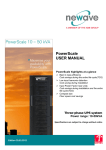
If for example a tour is selected and analysis mode “Comparison Diagram“ is chosen a diagram
appears in the right screen region displaying the associated data. At the bottom of the diagram the
voltage values are also displayed as a table. This table can be switched off by de-selecting the
checkbox “Show Table“. The chart type can be changed accordingly when the radio buttons are
clicked.
The minimum voltage value is displayed as a red line.
Figure 30 shows a scenario where tour data are displayed:
Figure 30: Comparison (one measurement selected)
Because the tour data in the tree is still selected the preview window contains the same information.
If the user selects another entry in the tree the preview changes accordingly. The analysis screen
region remains constant.
Do do a comparison between two tours the user should add a second tour to the analysis window.
This can be achieved by selecting the appropriate tree node with a double-click. Figure 31 on page
38 shows a comparison of the two tours of battery “12“ in area „TestGJ2b“.
Page 37
4 The First Steps
Figure 31: Comparison (two measurements selected)
The tour data of the battery are displayed simultanously, its charts are stacked. To put a third chart
into the diagram an appropriate tree node has to be selected with a double-click.
Restrictions:
●
It is not possible to mix tour data and capacity tests, even if they are from the same battery
●
If the measurement type should be switched the graphic windows has to be cleared first.
Page 38
5 Data Maintainance
5 Data Maintainance
5.1 Overview
CS-Manager distinguishes four objects in its database:
●
Area
●
Block Type
●
Battery
●
Measurement
Measurement data is imported from a device and cannot be manipulated by the user. Only remarks
can be attached to a measurement.
The maintenance operations
●
Create
●
Change
●
Delete
for the other objects are described in the sections 5.2 to 5.4.
5.2 Maintain Area Data
5.2.1
Overview
In the following sections the maintenance operations for areas are described. The attributes of an
area are explained only in the section “Create New Area“.
5.2.2
Create New Area
To create a new area the node „Area Data“ should be selected in the tree. When the button “New
Area“ is pressed the form according to figure 33 is displayed. The following attributes are
displayed:
Name
Used For
Area Name 1
Name for the area
Area Name 2
Additional name (may be empty)
Area Number
Unique Area ID
Remarks
mandatory
Unique
Page 39
5 Data Maintainance
Name
Used For
Country
Country
ZIP
ZIP Code
City
City
Street
Street
Name Contact Person
Name of a contact person
Phone Number Contact Person
Phone number of a contact person
Remarks
Remarks about the area
Remarks
Figure 32: Attributes of AREA
Figure 33: Create Area
If the button “Save“ is pressed CS-Manager checks the plausibility of the data. If the plausibility
checks fail appropriate error messages are issued. If the checks succeed a message box appears
Page 40
5 Data Maintainance
asking whether or not the data should be saved. If the user answers with “Yes“ the data is written
into the database.
When the user tries to select another item in the tree and the data has been changed, CS-Manager
asks whether or not the record should be saved before displaying the data of the new tree node.
5.2.3
Change an Existing Area
To change the data of an area the representing node in the tree has to be selected. If the button
“Save“ is pressed CS-Manager checks the plausibility of the data. If the plausibility checks fail
appropriate error messages are issued. If the checks succeed a message box appears asking whether
or not the data should be saved. If the user answers with “Yes“ the data is written into the database.
When the user tries to select another item in the tree and the data has been changed, CS-Manager
asks whether or not the record should be saved before displaying the data of the new tree node.
5.2.4
Delete an Area
To delete an area an area node in the tree has to be selected first. If the button “Delete“ is pressed
CS-Manager asks whether or not this record should be deleted. If the user answers with “Yes“ the
record will be removed from the database. The tree representation will be updated.
5.3 Maintain Block Type Data
5.3.1
Overview
In the following sections the maintenance operations for block types are described. The attributes of
a block type are explained only in the section “Create New Block Type“.
5.3.2
Create New Block Type
To create a new block type the node “Block Types“ has to be be selected in the tree. When the
button “New Block Type“ is pressed the form according to figure 34 is displayed.
Page 41
5 Data Maintainance
Figure 34: New Block Type
The following attributes are displayed:
Name
Used For
Manufacturer
Name of the battery manufacturer
Block Type
Description (e. g. What it is used for)
Block Design
Pb, NiCd, etc.
Remarks
mandatory
Float Voltage
Density
Temperature
Resistance
Connector
Block AC
Page 42
5 Data Maintainance
Name
Used For
Remarks
Test Time
Discharge Current
Capacity
Charge Current
Check voltage min
Check voltage max
Figure 35: Attributes of BLOCK TYPE
If the button “Save“ is pressed CS-Manager checks the plausibility of the data. If the plausibility
checks fail appropriate error messages are issued. If the checks succeed a message box appears
asking whether or not the data should be saved. If the user answers with “Yes“ the data is written
into the database.
When the user tries to select another item in the tree and the data has been changed, CS-Manager
asks whether or not the record should be saved before displaying the data of the new tree node.
5.3.3
Change an Existing Block Type
To change the data of an existing block type the representing node in the tree has to be selected. If
the button “Save“ is pressed CS-Manager checks the plausibility of the data. If the plausibility
checks fail appropriate error messages are issued. If the checks succeed a message box appears
asking whether or not the data should be saved. If the user answers with “Yes“ the data is written
into the database.
When the user tries to select another item in the tree and the data has been changed, CS-Manager
asks whether or not the record should be saved before displaying the data of the new tree node.
5.3.4
Delete an Block Type
To delete a block type an appropriate node in the tree has to be selected first. If the button “Delete“
is pressed CS-Manager asks whether or not this record should be deleted. If the user answers with
“Yes“ the record will be removed from the database. The tree representation will be updated.
Page 43
5 Data Maintainance
5.4 Maintain Battery Data
5.4.1
Overview
In the following sections the maintenance operations for batteries are described. The attributes of a
battery are explained only in the section “Create New Battery“.
5.4.2
Create New Battery
To create a new battery an area node should be selected in the tree. The area node represents the
area in which the battery is located. When the button “New Battery“ is pressed the following form
is displayed:
Figure 36: New Battery Data
Its attributes are explained in a table (see figure 37).
Page 44
5 Data Maintainance
Name
Used For
Remarks
Battery ID
Identifier, unique within the associated area Mandantory, unique
Name
Name of the battery
mandantory
Block Type
Link to an existing block type
mandantory
Usage
What is the battery used for
Number of Cells
Number of cells building the battery
Min voltage
Minimum voltage (calculated from the
number of cells and the minimum cell
voltage)
Min voltage per cell
Minimum cell voltage (default obtained
from the appropriate block type record)
Max voltage
Maximum voltage (calculated from the
number of cells and the maximum cell
voltage)
Max voltage per cell
Maximum cell voltage (default obtained
from the appropriate block type record)
Capacity
Capacity (default obtained
appropriate block type record)
Discharge current
Discharge Current (default obtained from
the appropriate block type record)
Discharge time
Discharge time (default obtained from the
appropriate block type record)
from
the
Shunt mV
Shunt A
No 1 at cell 1, No 1 at cell n
Count direction: is number one at the first
or last cell?
Area
Area in which the battery is located
Room
Description
Remarks
Figure 37: Attributes of BATTERY
If the button “Save“ is pressed CS-Manager checks the plausibility of the data. If the plausibility
checks fail appropriate error messages are issued. If the checks succeed a message box appears
Page 45
5 Data Maintainance
asking whether or not the data should be save. If the user answers with “Yes“ the data is written into
the database.
When the user tries to select another item in the tree and the data has been changed, CS-Manager
asks whether or not the record should be saved before displaying the data of the new tree node.
5.4.3
Change an Existing Battery
To change a battery record the representing node in the tree has to be selected. If the button “Save“
is pressed CS-Manager checks the plausibility of the data. If the plausibility checks fail appropriate
error messages are issued. If the checks succeed a message box appears asking whether or not the
data should be saved. If the user answers with “Yes“ the data is written into the database.
When the user tries to select another item in the tree and the data has been changed, CS-Manager
asks whether or not the record should be saved before displaying the data of the new tree node.
5.4.4
Delete an Battery
To delete a battery a battery node in the tree has to be selected first. If the button “Delete“ is pressed
CS-Manager asks whether or not this record should be deleted. If the user answers with “Yes“ the
record will be removed from the database. The tree representation will be updated.
Page 46
6 Data Analysis
6 Data Analysis
6.1 Overview
The following sections describe the handling of (measurement) data. To work with measurement
data first they have to be downloaded from the measurement device (section 4.3.7). Usually area
and battery definitions are uploaded to the device before the measurement tasks are performed. If
the device is used in an area the software CS-Manager is not configured for it might be that area and
battery IDs are downloaded which are inconsistent with the database. In that case the user may reassociate area, battery and measurement data (see section ). When the database is consistent analysis
tasks may be performed. In the following sections the supported analysis types are explained.
6.2 Print or Export Main Data
The objects
●
Block Type
●
Area
●
Battery
in CS-Manager can be printed by right-clicking a node in the tree. This opens a context menu with
the entries “Print“ and “Export“. If the user selects “Print“ the information associated with the
selected tree node is sent to a printer. If “Export“ is used, an appropriate CSV file is created.
The following table explains the results when using the context menu on the different tree items:
Node Type
Result
„Block Types“
List of block types stored in the current profile
Single Block Type
Attributes of the selected block type
Area Data
List of areas stored in the current profile
Single Area
Attributes of the selected area
Battery
Attributes of the selected battery
„Unknown Objects“
List of unknown batteries with its areas stored in the current profile
„Unknown Areas“
List of unknown areas stored in the current profile
„Unknown Batteries“
List of unknown batteries stored in the current profile
Single Measurement
Message: Measurement data can be printed in the analysis window
Figure 38: Export or Print Data
Page 47
6 Data Analysis
6.3 Analysis of Measurement Data
6.3.1
Overview
Currently two analysis modes are supported in CS-Manager:
●
Trend Analysis
●
Comparison
With a trend analysis the focus is on the battery's cells and visualise their history (e.g. cell voltage
over time). In a comparison batteries are compared (e.g. voltage over cells). The following sections
describe how a trend analysis or a comparison can be performed with CS-Manager.
6.3.2
6.3.2.1
Trend Analysis
Overview
In an trend analysis the history of the battery's cells are visualised. Voltage values collected in
several tours are displayed over the time axis. This allows to judge the development of a battery. A
trend can be displayed either as a table or a diagram. Both variants allow to navigate through the
battery's cells in the form.
6.3.2.2
Trend Table
To display a trend of a battery as a table the following steps have to be performed:
1. Select an a battery node in the tree
2. Press menu button “Trend Table“
3. To finish press menu button “End Trend or Comparison“
Figure 39 shows how to start a trend analysis. In Figure 40 the cell voltages of the battery are
displayed as a table. With the buttons “Previous Cell“ and “Next Cell“ the user can navigate
through the battery's cells. The menu entry “End Trend or Comparison“ becomes black when a trend
or comparison table/digram is display. The menu entry can be used to finish the analysis task and to
return to the navigation mode of CS-Manager.
Page 48
6 Data Analysis
Figure 39: Start Trend Table
Figure 40: Trend Table
Page 49
6 Data Analysis
6.3.2.3
Start Trend Diagram
To display a trend of a battery as a table the following steps have to be performed:
4. Select an a battery node in the tree
5. Press menu button “Trend Table“
6. To finish press menu button “End Trend or Comparison“
Figure 41 shows how to start a trend diagram. Figure 42 shows the available he cell voltage values
of the battery. With the buttons “<“ (previous cell) and “>“ (next cell) the user can navigate through
the battery's cells. The buttons “<<“ and “>>“ allow to jump to first or to the last cell. The menu
entry “End Trend or Comparison“ becomes black when a trend or comparison table/digram is
display. The menu entry can be used to finish the analysis task and to return to the navigation mode
of CS-Manager.
Figure 41: Start Trend Diagram
Page 50
6 Data Analysis
Figure 42: Trend Diagram
The design of the diagram can be influenced with the buttons and check boxes at the top of the
window. For example, the chart type can be changed from xy chart to a bar diagram, the 3D view
can be switched off, etc.
6.3.2.4
Print or Export Trend Diagram
If the diagram and the table (if visible) should be printed or exported as a CSV file, the buttons at
the left side of the diagram can be used.
6.3.3
6.3.3.1
Comparison
Overview
A comparison allows to display parameters of a battery (e.g. voltage) over cells and compare them
with other measurements. If a comparison diagram is used the associated graphs can be stacked.
Page 51
6 Data Analysis
6.3.3.2
Comparison Table
To display a comparison of a battery as a table the following steps have to be performed:
7. Select an a battery node in the tree
8. Press menu button “Comparison Table“
9. To finish press menu button “End Trend or Comparison“
Figure 43 shows how to start a comparison analysis:
Figure 43: Start Comparison Table
Figure 44 shows a comparison table of a defective battery. The voltage values which are less than
the minimum voltage value defined for this battery are indicated with a red instead of a green
background. The navigation through the cells can be done with the buttons „Previous Cell“ and „42
shows a comparison table of a defective battery. The voltage values which are less than the
minimum voltage value defined for this battery are indicated with a red instead of a green
background. The navigation through the cells can be done with the buttons “Previous Cell“ and
Page 52
6 Data Analysis
“Next Cell“.
Figure 44: Comparison Table (defective battery)
To finish the analysis task the menu button „End Trend or Comparison“ should be used.
6.3.3.3
Comparison Diagram
A comparison diagram allows to display more than one diagram simultanously. The only restriction
is that the types (tour or capacity test) of measurement have to be homogenously. It is not possible
to mix tour and capacity test data. To put a candidate to the analysis window just double-click the
node representing the measurement. Figure 45 shows the comparison with one tour selected. The
tree still can be browsed, the preview window changes accordingly. If a second tour should be
selected, again a double-click on the tree node is required (see figure 46).
Page 53
6 Data Analysis
Figure 45: Comparison Diagram: One Tour
Figure 46: Comparison Diagram: Two Tours
Page 54
6 Data Analysis
If a new comparison should be started it is not necessary to close the graphic window with “End
Trend or Comparison“. Instead, the graphic can be cleared with the menu entry “Clear Graphics
Window“ and the selection process can be started again.
Figure 47: Clear Graphics Window
6.3.3.4
Print or Export Comparison
If the diagram and the table (if visible) should be printed or exported as a CSV file, the buttons at
the left side of the diagram can be used (see figure 46).
Page 55
7 Appendix
7 Appendix
7.1 Release Notes
7.1.1
Version 1.2
7.1.2
Version 1.1
7.1.3
Version 1.0
N/A
7.2 Future Development
The following features will be supported in future releases:
●
Support of multiple Profiles
●
Support of multiple Languages
●
Standard Reports for Measurements
Page 56
8 References
8 References
[1]
Datasheet CRM.2001, Jost Electronics, http://www.cellizer.com
[2]
Datasheet CS-4001/127, Jost Electronics, http://www.cellizer.com
1
Page 57