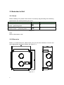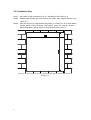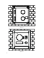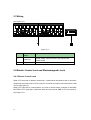
1
2-Wire ECL-VIP200 User’s Manual V1.0.0 i Table of Contents Table of Contents .....................................................................................................................i 1 Product Overview ....................................................................................................... 1 1.1 List of Models ................................................................................................................. 1 1.2 Structure ........................................................................................................................ 1 1.3 2 2.1 2.2 1.2.1 Dimension ........................................................................................................... 1 1.2.2 Front Panel ......................................................................................................... 2 1.2.3 Rear Panel ........................................................................................................... 3 System Networking ........................................................................................................ 3 1.3.1 One-to-One Scene .............................................................................................. 4 1.3.2 Group Call Scene................................................................................................. 4 Install VTO .................................................................................................................. 5 Direct Installation ........................................................................................................... 5 2.1.1 Screw .................................................................................................................. 5 2.1.2 Dimension ........................................................................................................... 6 2.1.3 Installation Step .................................................................................................. 6 Embedded in Wall .......................................................................................................... 8 2.2.1 Screw .................................................................................................................. 8 2.2.2 Dimension ........................................................................................................... 8 2.2.3 Installation Step .................................................................................................. 9 2.3 Wiring ........................................................................................................................... 11 2.4 Electric Control Lock and Electromagnetic Lock .......................................................... 11 3 3.1 i 2.4.1 Electric Control Lock ......................................................................................... 11 2.4.2 Electromagnetic Lock........................................................................................ 12 Installation Debugging ............................................................................................. 13 WEB Setup.................................................................................................................... 13 3.2 4 4.1 4.2 4.3 General Config ............................................................................................................. 14 Web Config ............................................................................................................... 16 System Config............................................................................................................... 16 4.1.1 Local Config....................................................................................................... 16 4.1.2 LAN Config ........................................................................................................ 17 4.1.3 Indoor Manager ................................................................................................ 17 4.1.4 Network Config ................................................................................................. 19 4.1.5 Video Set ........................................................................................................... 19 4.1.6 User Manage..................................................................................................... 20 Info Search ................................................................................................................... 21 4.2.1 Call History ........................................................................................................ 21 4.2.2 Alarm Record .................................................................................................... 22 Status Statistics ............................................................................................................ 22 4.3.1 4.4 5 5.1 VTH Status ........................................................................................................ 22 Logout .......................................................................................................................... 22 Basic Function Introduction ..................................................................................... 23 Call Function................................................................................................................. 23 5.1.1 Call Manager Center ......................................................................................... 23 5.1.2 Call User ............................................................................................................ 24 5.1.3 Group Call ......................................................................................................... 24 5.2 Monitor ........................................................................................................................ 27 5.3 Unlock Function ........................................................................................................... 27 5.4 Compensation of Light ................................................................................................. 28 5.5 Vandal Proof................................................................................................................. 28 5.6 Restore Backup ............................................................................................................ 28 6 FAQ ........................................................................................................................... 29 Appendix 1 Technical Specifications ....................................................................................... 30 Appendix 2 Technical Specifications ....................................................................................... 31 Appendix 2.1 Cable Specification ............................................................................................ 31 Appendix 2.2 Power Extension Line Specification................................................................... 31 ii Appendix 2.3 Embedded Box .................................................................................................. 31 Appendix 3 VTMS .................................................................................................................... 32 Appendix 4 VTMS Client .......................................................................................................... 34 Appendix 4.1 Config Network Address.................................................................................... 34 Appendix 4.2 Create Organization .......................................................................................... 36 iii Important Safeguards and Warnings Please read the following safeguards and warnings carefully before using the product in order to avoid damages and losses. Note: Do not expose the device to lampblack, steam or dust. Otherwise it may cause fire or electric shock. Do not install the device at position exposed to sunlight or in high temperature. Temperature rise in device may cause fire. Do not expose the device to humid environment. Otherwise it may cause fire. The device must be installed on solid and flat surface in order to guarantee safety under load and earthquake. Otherwise, it may cause device to fall off or turnover. Do not place the device on carpet or quilt. Do not block air vent of the device or ventilation around the device. Otherwise, temperature in device will rise and may cause fire. Do not place any object on the device. Do not disassemble the device without professional instruction. Warning: Please use battery properly to avoid fire, explosion and other dangers. Please replace used battery with battery of the same type. Do not use power line other than the one specified. Please use it properly. Otherwise, it may cause fire or electric shock. Special Announcement This manual is for reference only. All the designs and software here are subject to change without prior written notice. All trademarks and registered trademarks are the properties of their respective owners. If there is any uncertainty or controversy, please refer to the final explanation of us. Please visit our website for more information. iv 1 Product Overview 1.1 List of Models Model Chassis Material Color Unlock IC card ECL-VIP200 Metal Silver N/A via Button Type Lock Control Module Mechanical key Built-in 1.2 Structure 1.2.1 Dimension Before you install the device, please make sure you know the dimension of device and select appropriate installation method. See Figure 1- 1. Figure 1- 1 1 1.2.2 Front Panel Figure 1- 2 No. 2 Port Name Note 1 MIC Audio input. 2 Camera It monitors corresponding door region. 3 Compensation Light Light compensation will automatically turn on during monitoring, calling, or connecting status if there is no enough light in environment. 4 Speaker Audio output. 5 User Nameplate Display username and other info. 6 Call Button Call center or VTH. 1.2.3 Rear Panel Figure 1- 3 No. Component Name Note 1 Camera Angle Adjustment Adjust camera angle. 2 Vandal-proof Switch When VTO if forced to leave wall, it will alarm and report to MGT center. 3 User Port Connect to lock, door sensor feedback and unlock button. 4 Project Port Reserved for project staff use. 1.3 System Networking This chapter mainly introduces usage of digital VTO, please read the following content and install the device according to your actual condition. 3 1.3.1 One-to-One Scene Visitor press Call button to call residence (as VTH) or Center. See Figure 1- 4. Figure 1- 4 1.3.2 Group Call Scene When visitor press Call button on VTO, multiple VTHs will ring at the same time. User can call, hang up, and unlock on any of these VTHs. Note: VTH has 1 master VTH and up to 3 extension VTHs. See Figure 1- 5. Figure 1- 5 4 2 Install VTO 2.1 Direct Installation 2.1.1 Screw Before installing VTH, please check screws on accessory bag according to the following specifications and install by following this guide. Component Name Illustration Quantity M3×6 Hex slot pan head tail machine screws --- galvanizing white 4 M3×8 Cross recessed countersunk head tail machine screws --- galvanizing white 4 ST3×18 Cross recessed countersunk head tail tapping screws --- galvanizing white 4 ¢ 4 White expansion tube 6×30mm Chart 2- 1 Note: M3x6 or M3x8 either is OK. 5 2.1.2 Dimension Before you install the device, please make sure you know the dimension of device and select appropriate installation method. See Figure 2- 1. Figure 2- 1 2.1.3 Installation Step Step 1. Install metal bracket into the groove on wall. At spot 1 fasten screw (ST3×18 Cross recessed countersunk head tail tapping screws --- galvanizing white), and fix metal bracket on wall. See Figure 2- 2 Step 2. Align the device on metal bracket according to screw hole. At spot 2 fasten screw (M3×8 Cross recessed countersunk head tail machine screws --- galvanizing white), and fix device on metal bracket. See Figure 2- 3. 6 Figure 2- 2 Figure 2- 3 7 2.2 Embedded in Wall 2.2.1 Screw Before installing VTH, please check screws on accessory bag according to the following specifications and install by following this guide. Component Illustration Quantity M3×6 Hex slot pan head tail machine screws--- galvanizing white 4 M3×8 Cross recessed countersunk head tail machine screws --- galvanizing white 4 Chart 2- 2 Note: M3x6 or M3x8 either is OK. 2.2.2 Dimension Before you install the device, please make sure you know the dimension of device and select appropriate installation method. See Figure 2- 4. Figure 2- 4 8 2.2.3 Installation Step Step 1. Dig a hole on wall, its dimension is 117*128*80(mm).See Figure 2- 5. Step 2. Embed metal bracket into wall until its four peaks lean against the wall. See Figure 2- 6. Step 3. Align the device on metal bracket according to screw hole. At 2 spots fasten screws (M3×8 Cross recessed countersunk head tail machine screws --galvanizing white), and fix device on metal bracket. See Figure 2- 7. Figure 2- 5 9 Figure 2- 6 Figure 2- 7 10 2.3 Wiring See Figure 2- 8. Figure 2- 8 No. 1 2 Component Name Note User Port Power supply, connect to lock, door sensor and unlock button. Project Port Reserved for project staff use. 2.4 Electric Control Lock and Electromagnetic Lock 2.4.1 Electric Control Lock When VTO connects to electric control lock, it means that the positive end of electronic control lock connects to NO of VTO (user port 10) while its negative end connects to COM of VTO (user port 12). When VTO connects to unlock button, one end of unlock button connects to UNLOCK BUTTON of VTO (user port 7) while the other end connects to GND of VTO (user port 9). See Figure 2- 9. 11 Figure 2- 9 2.4.2 Electromagnetic Lock When VTO connects to electromagnetic lock, it means that the positive end of electromagnetic lock connects to NC of VTO (user port 11) while its negative end connects to COM of VTO (user port 12). When VTO connects to door sensor in electromagnetic lock, one end of door sensor connects to FEEDBACK of VTO (user port 8) while the other end connects to GND of VTO (user port 9). See Figure 2- 10. Figure 2- 10 12 3 Installation Debugging Warning: Before debugging, the staff shall be familiar with device’s installation, wiring and usage. Before debugging, check wiring for short or open circuit. When staff find each circuit is normal, plug the device to power. After debugging, clear the site. 3.1 WEB Setup If you first use VTO, you may need to operate according to the following steps: Step 1. First, make sure your PC and the VTO are well connected, and follow steps below to login WEB interface. Step 2. In Internet Explorer, input IP address of the VTO, and press Enter. System shows Figure 3- 1. Step 3. Input Username and Password. Step 4. Click on Login. Note: Default IP address of VTO is 192.168.1.110. Default username and password is admin/admin. After first login, please change your password. Figure 3- 1 13 3.2 General Config If you first use VTO, you may need to operate according to the following steps: Step 1. In Internet Explorer, input IP address of the VTO, and press Enter. Note: Default IP address of VTO is 192.168.1.110. Default username and password is admin/admin. After first login, please change your password. Step 2. In WEB interface, select System Config>Local Config, set video format as WVGA as in Figure 3- 2. Figure 3- 2 Step 3. In System Time tab, click on Sync PC to make VTO time the same with PC. Step 4. Select System Config>Network Config, set VTO IP, Subnet Mask and Default Gateway. See Figure 3- 3. Figure 3- 3 14 Step 5. (Optional) If VTO connects to VTMS platform, System Config>LAN Config, set Area No. Section No. Building No. and etc. These parameters must match settings on VTMS Client. Please refer to Appendix 2 and 3. See Figure 3- 4. Figure 3- 4 Figure 3- 5 Note: When you configue one-to-multiple scene, different VTOs shall have different VTO no. and same building no. and unit no., in order to form a proper network. 15 4 Web Config This chapter introduces VTO WEB interface and its parameters, and hot to configure them. 4.1 System Config 4.1.1 Local Config 4.1.1.1 Local Config In Local Config interface, you can view VTO model, version info and etc. Figure 4- 1 Parameter Note Video Format Set video format that collected by the camera, including: WVGA and D1. WVGA resolution is 800×480; D1 resolution is 704×576. Device Type Display device type. Frame Rate NTSC: 30 fps, PAL: 25 fps. Reboot Date On the set date, device will automatically reboot. Sensitivity of light to open fill Set threshold of light. Version Info Display device version info. Default Only restore current Local Config page to default settings. 16 4.1.1.2 A&C Manager Figure 4- 2 Parameter Unlock Interval Note Responding Unlock Period Door Time Sensor The interval between current unlock and next one, unit is second. Period door remains unlocked, unit is second. Check Check Door Sensor Signal Before Lock When only use door sensor, check”Check Door Sensor Signal Before Lock”, Set “Door Sensor Check Time” to enable it. When door remains unlocked over set door sensor check time, it alarms. 4.1.1.3 System Time Here you can set date format, time format, and input system date and time. You can also click on Sync PC to synchronize system time with PC time. 4.1.2 LAN Config Here you can register VTO to center and set how to call center. Please refer to Ch 5.1.1. 4.1.3 Indoor Manager In Indoor Manager interface, you can add VTH (digital indoor station), view VTH info and delete VTH. Figure 4- 3 17 Add VTH In Indoor Manager interface, click on Add. The system pops up a window as in Figure 4- 4. Figure 4- 4 Fill in VTH info as user’s name, VTH short no. and IP address. Note: VTH short no. consists of four digits, the first two digits can be within 01~99, the last two digits can be within 01~16. Note: Parameters with * are mandatory. 18 4.1.4 Network Config Here you can set VTO IP address, Subnet Mask and Default Gateway. After you have modified IP address, Web page will reboot and go to the new IP address web page. See Figure 4- 5. Figure 4- 5 4.1.5 Video Set You can set video effect and volume in Video Set interface. See Figure 4- 6. Figure 4- 6 19 Parameter Note Gain Gain limit of video basic parameter. Scene Mode Select mode: automatic, sunny, night and etc. Day/Night Mode Color mode. Back Light Mode Back light for special environment. Mirror Make image displayed in mirror. Flip Display image in flip. VTO Mic Volume Set VTO MIC volume size. VTO Beep Volume Set VTO beep volume size. Default Reset video effect and volume to default. Unlock Unlock via web. 4.1.6 User Manage Only when you login as admin, you can add, modify, delete and view user info in User Manage interface. Add User In User Manage interface, click on Add User, system pops up Figure 4- 7. Fill in user info. Figure 4- 7 20 Modify User In User Manage interface, click on , system pops up Modify User interface. Check Change Password, and change password and remark, see Figure 4- 8. Figure 4- 8 Delete User In User Manage interface, click on to delete user. 4.2 Info Search 4.2.1 Call History Here you can view call history of VTO in Call History interface. It can save up to 1024 items. . Figure 4- 9 21 4.2.2 Alarm Record You can search VTO alarm record on Alarm Record interface with storage up to 1024 items. See Figure 4- 10. Figure 4- 10 4.3 Status Statistics 4.3.1 VTH Status Here you can view connection status of VTH. Status Offline: VTO and VTH are not connected, you cannot call, monitor, talk or etc. Online: VTO and VTH are connected, you can call, monitor, talk and etc. MON Unmon: VTH is not monitoring. Onmom: VTH is monitoring. See Figure 4- 11. Figure 4- 11 4.4 Logout Here you can reboot device or logout. Click on logout to log out the system and it returns to login page. 22 5 Basic Function Introduction 5.1 Call Function 5.1.1 Call Manager Center Check Register to the MGT Center, you can touch the Call button to call manager center. Now VTO can only call MGT Center, cannot call VTH. Manager center’s time can be set on management platform or villa VTO’s web-end. Once manager center picks up the call, you can perform a visual bidirectional talk with the manager center. You can touch the button on VTO to end call at any time. Step 1. According to VTO configured for the center, fill in building no, building unit no. and VTO no. Step 2. In LAN Config, check register to the MGT center, as in Figure 5- 1. Step 3. Fill in MGT center IP address and MGT port no. Step 4. Set call VTS time. Within this period, VTO can only call the center. Step 5. Check Call VTS or not. Step 6. Confirm all config, and click on OK. Enter Logout Reboot Devices, to manually reboot the device. Figure 5- 1 23 5.1.2 Call User Press Call button under standby status, and the VTO will call user. User may monitor VTO from VTH. On VTH, press Unlock button to unlock door. When VTH picks up, you can start talk with the VTH. If no one answers the call, then the call will end automatically and device returns to standby status. 5.1.3 Group Call Group call is mainly used for one VTO. Press Call button on VTO to call multiple VTH at the same time. VTH consists of master VTH and extension VTH. A system can only have a max of 1 master VTH and 5 extension VTHs. Please refer to VTO2000A Series Installation Guide V 1.0.0. Set VTO Step 1. Select System Config>Indoor Station Manager, system shows Indoor Station interface. Step 2. In Indoor Station Manager interface, click on to delete default VTH. Step 3. Click on Add, input VTH Short No., IP Address (optional) to add a VTH. See Figure 5- 2. Note: In Indoor Station interface, you only need to add main VTH, and you do not need to add extension. 24 Figure 5- 2 Note: Paramete with * are mandantory to be set. Step 4. In LAN Config interface, check Group Call, and click on OK. See Figure 5- 3. Step 5. After config is complete, enter Logout interface to reboot VTO. Figure 5- 3 25 Set Main VTH Step 1. On VTH screen, press System Settings>Project Settings, input password (default is 002236) to enter Project Settings interface. Step 2. Press Product Info, input Room No., Local IP and etc as in Figure 5- 4. Note: Room No. must match setting in VTH Short No. In Figure 5- 4. Figure 5- 4 Step 3. Press Network, input VTO IP Address. See Figure 5- 5. Figure 5- 5 26 Set Extension Step 1. On VTH screen, press System Settings>Project Settings, input password (default is 002236) to enter Project Settings interface. Step 2. Press Product Info. Press Master, Master icon becomes Extention icon. Step 3. Set Room No. (i.e. 1101-1), input IP Address, Subnet Mask and Gateway. Step 4. In Master IP, input IP of the main VTH. After competion, extension will automatically sync with main VTH info configured by user. See Figure 5- 6. Figure 5- 6 5.2 Monitor Both VTS and VTH are able to monitor this VTO by enabling the camera to capture local circumstance. 5.3 Unlock Function Unlock by Center When center is called, calling or monitoring, center can remotely unlock door. VTO will return to standby interface after call ends or countdown stops. Unlock by VTH When VTH is called, calling or monitoring, VTH can remotely unlock door. VTO will return to standby interface after call ends or countdown stops. 27 5.4 Compensation of Light In dark environment or at night, the VTO adopts auto photoreception technology which achieves light compensation in connecting status. 5.5 Vandal Proof There is one channel of vandal proof which will generate alarm sound and report to the manager center once VTO is forced to leave the wall. 5.6 Restore Backup Restore Card Info If you encounter abnormality with card info or accidently restore default settings, you can restore card info with this function. Restore VTH Info If VTH info is mistakenly changed, you can restore VTH info with this function. Note: Every half hour, VTO automatically saves card and VTH info in the system. If you want to restore card and/or VTH info, you must restore within half hour after your last operation that change these info. 28 6 FAQ 1. 2. 3. 4. 5. Q: I pressed Call button, and the indicator turned on, but the VTO did not start a call? A: Please check your operation process. Q: How to end a call when I am calling? A: Please press button on VTO and there will be sound from the device. Q: The device could not boot up and there was no sound or light. A: Please check if power supply is well plugged. Q: My call did not go though. A: It is network connection error; please check the cables of the device and its extension. Q: I have other problems not included above. A: Please contact technical staffs for assistance. 29 Appendix 1 Technical Specifications Model System Video Audio Operation Mode Network General 30 ECL-VIP200 Main Process Embedded micro controller OS Embedded Linux os Video Compression Standard H.264 Input/Sensor 1.3 Megapixel CMOS HD camera Night Vision Support Input Omnidirectional Mic Output Built-in speaker Talk Support bidirectional talk Input Single key input Door Lock Status Check Support (optional) Ethernet 10M/100Mbps self-fit Network Protocol TCP/IP Power DC 24V Consumption Standby ≤1W; working ≤7W Working Temperature ﹣30℃~+60℃ 10%~90%RH Relative Humidity Dimension (L×W×H) 129.9mm×32.2mm×140mm Weight 0.8kg Appendix 2 Technical Specifications Appendix 2.1 Cable Specification The wiring length between VTO and VTH is LN, so reasonable specification of wiring is: Cable Specification 0<LN≤50m 50<LN≤100m UTP Cat5e/Cat6: 10 ohm/100m Optional Optional UTP Cat5e/Cat6: 18.8 ohm/100m Optional Not optional Note: Please do not let LN be over 100m. Appendix 2.2 Power Extension Line Specification The wiring length between VTO and adaptor is LC, so reasonable specification of extnsion line is: Extension Line Specification 0<LC≤30m 30<LC≤100m 20AWG Optional Not optional 18AWG Optional Optional 17AWG Optional Optional Note: Before plugging extension line to power, make sure its positive and negative end are correctly wired. Appendix 2.3 Embedded Box 31 VTO Model Embedded Box ECL-VIP200 Case 126*115 Appendix 3 VTMS Check Installation Environment This manual makes Window XP as example to introduce how to modify IP of PC inorder to connect VTMS and monitoirng system. Step 1. Select Start>Control Panel>Network Connection>Local Area Connection, right click on Local Area Connection icem, select Properties, see Appendix 3- 1. Appendix 3- 1 Step 2. View and modify IP address, make it in the same segment with VTO. See Appendix 3- 2. Appendix 3- 2 32 Step 3. After complete modification, select Start>Run, input “cmd”, click on OK. Enter command interface, input “ping” + IP of the VTO. If it obtains communication data, then VTO and the PC are connected. See Appendix 3- 3. Appendix 3- 3 Enable VTMS The following mainly introduces how to config VTMS for you to login VTO and use VTMS. Step 1. Install VTMS on PC. Step 2. Double click on , click on Start service, and VTMS will boot up. Appendix 3- 4 33 Appendix 4 VTMS Client This following mainly introducts how to config VTMS Client. Appendix 4.1 Config Network Address Step 1. Install VTMS Client on PC. Step 2. Double click on , in pop-up box input username, password, IP address, port and etc. Click on Login. See Appendix 4- 1. Note: Default username and password is admin and 123, respectively. After first successful login, please change password. Appendix 4- 1 Step 3. In main interface, click on Device MGR. See Appendix 4- 2. Appendix 4- 2 34 Step 4. Double click on VTS parameter collumn, sustem pops up Edit device box, input PC’s IP address. See Appendix 4- 3. Appendix 4- 3 Step 5. Click on Save. Input project password (default project password is 123). Step 6. Re-login VTMS, you can see VTMS is successfully configured as in Appendix 44. Appendix 4- 4 35 Appendix 4.2 Create Organization First you must build up environmrnt and set VTMS server, please refer to Appendix 3. This chapter takes example of a residence with 10 buildings and 2 units. Create Residence Organization Step 1. In VTMS main interface, select Organization, click on Batch Add. System pops up Batch Add box, see Appendix 4- 5. Appendix 4- 5 Step 2. Click on OK to save. The created organization is as in Appendix 4- 6. Appendix 4- 6 36 Add VTO Step 1. In VTMS main interface, select Device MGR, click on Add, system pops up Batch Add box. Step 2. Fill in info according to your actual condition, and click on Save. See Appendix 47. Appendix 4- 7 37 Add VTH Step 1. In VTMS main interface, select Device MGR, click on Batch Add, system pops up Batch Add box. Step 2. Fill in info according to your actual condition, and click on Save. See Appendix 48. Appendix 4- 8 Note: This manual is for reference only. Slight difference may be found in user interface. All the designs and software here are subject to change without prior written notice. All trademarks and registered trademarks are the properties of their respective owners. If there is any uncertainty or controversy, please refer to the final explanation of us. Please visit our website or contact your local service engineer for more information. 38