1
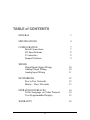
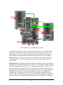
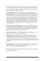
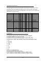
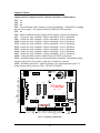
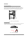
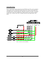
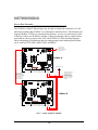
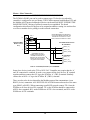
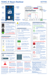
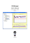
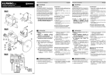
INTEGRATED SYSTEMS AND CONTROL INC. PCMNET HARDWARE USER’S MANUAL 2007 Integrated Systems and Control. Inc. PO Box 7682, Auburn, CA 95604 Phone 530-878-9038 • Fax 530-878-9137 www.isacinc.com 1 V7.xx TABLE of CONTENTS GENERAL 3 SPECIFICATIONS 4 CONFIGURATION Board Connections I/O Specifications J Connectors Jumper Positions 7 7 8 8 9 WIRING Digital Input/Output Wiring Analog Output Wiring Analog Input Wiring 10 10 11 NETWORKING Peer to Peer Networks Master – Slave Networks 12 12 13 OPERATOR INTERFACES TriNet Language via Telnet Protocol User Programmable Displays 14 14 15 WARRANTY 16 2 GENERAL The PCMNET expands ISAC’s PCM series of controls with expanded I/O capability and expanded Internet connectivity. The PCMNET shares the basic programming, logging and communications features of the PCM400I with expanded local and networked I/O and an Ethernet 10BaseT network. The PCMNET can be connected to up to two RLY80 Relay boards or Opto22 I/O rails and an Analog Expansion board to provide up to 16 DI/16 Relay DO/16 AI and 2 AO. We believe that the PCMNET is a product that provides the best combination of software functionality, packaging flexibility, short development cycle and low cost. The PCMNET may be directly connected to a 10BaseT Ethernet network for access via several different Ethernet protocols. The PCMNET retains the compatibility with the Modbus RTU RS485 network protocol on a dedicated channel. The PCMNET may be used as a Modbus RTU Master or Slave device on any Modbus RTU compatible network. When configured as a Network Master, up to 32 slaves (v7.21) may be connected to it’s RS485 network port. When configured as a Network Slave, the PCMNET may be connected to any Modbus RTU network and be used as a “Smart” network device. ISAC designed Modbus RTU network masters have expanded network functions that go beyond the standard Modbus RTU capabilities. FIG 1 - PCMNET W/ ON BOARD MODEM 3 SPECIFICATIONS PCMNET Board Size: Height = 5.75”, Width = 8.0”, and Depth = 2.0” Input Power: 24VDC +-0.2 at 1.2 Amps (including (1) RLY80). The input power is fused at 1.25 Amps and there is a power switch on the board to switch the main input power. The field terminals for connection of power are on a 3 position terminal strip, TB4. TB4-1 is used to connect 24VDC power, and TB4-3 is the RET return to the power supply. If a second RLY80 Board is to be used with the control, the fuse value and the 24VDC power requirement will need to be increased by 0.4 Amp. In this case, a 1.6 Amp fuse should be used and a power supply capable of supplying >=1.6 Amps should be used. If an Opto22 G4 I/O rail system is to be used, it will require a separate 5.0 VDC , >= 0.4A output power supply to power the rail and plugin modules. Output Power: Terminals are provided on the board for providing power for external sensors and output relays. A 24vdc switched terminal, TB4-2, is available for powering external sensors, limited to 0.25 Amp current total. The power available for external sensors must be considered along with RLY80 boards that may be required, when determining the capacity of the main 24 VDC power supply. Analog Inputs: The PCMNET has terminals for 8 analog inputs at 12 bit resolution which may be used as either 0-5VDC, 4-20ma, or 10K Thermistor temperature. A board jumper for each input may be used to connect the input to a 250 Ohm 1% resistor for 420ma inputs. The PCMNET Board is equipped with a 10 pin ribbon connector that allows the connection of one Expansion Analog Input Board to allow the addition of 8 more analog inputs (AI#9 thru AI#16). Therefore, the maximum number of field accessible analog inputs with an expansion board is 16 analog inputs. Digital Inputs: The PCMNET has 16 digital inputs (DI#1 thru DI#16). Inputs DI#1 to DI#8 may be accessed at TB3-1 to TB3-8 and are available in the J7 expansion connector. DI#9 to DI#16 are accessed through the J8 expansion connector. The PCMNET DI’s are self-powered from the 24VDC power such that only a contact closure connected between the DI and a RET terminal is required to activate them. Screw terminals on the PCMNET Board are provided for connections. Internally these inputs may be defined for use as general purpose inputs, status inputs intended to trigger alarms if the corresponding digital output does not switch, as a timed latching input useful in logic rules to provide temporary user overrides, and for accumulating pulses such as from a power meter or flow meter. When a RLY80 relay board is attached to the J7 connector of the PCMNET, the digital status inputs of the relay board are duplicated (or’d with the PCMNET board TB3 terminated inputs). Connecting a second RLY80 board to J8 expands the number of DI’s to 16. Inputs DI9 to DI16 are terminated on the RLY80 board. 4 RO 9-16 DI 9-16 24 VDC Rly80 DO 1-8 DI 1-8 AI 9-16 RO 1-8 DI 1-8 AIXP Rly80 PCMNet RS485 Network Ethernet Network AI 1-8 AO 1-2 FIG 2 - PCMNET W/ (2) RLY80 AND (1) AIXP A specially designed Opto22 rail may be used to directly connect J7 or J8 such that line voltage DI’s can be directly used. The Opto22 rail can accept 8 DI’s and 8 DO’s. The Digital Inputs 1-8 may be configured to function as a pulse accumulator. The Digital Input Definition programming screen include attributes for Pulse Sum Period and for a Multiplier that may be used to convert flow meter and power meter output signals into measured quantities. The maximum pulse rate that can be accepted without error is 25 pulses/second. Digital Outputs: The PCMNET board has 8 solid state (sinking) 24VDC digital outputs terminated on the PCMNET Board (TB3-9 to TB3-16). Each output is capable of sinking (switching to the RET terminal, TB3-17,18) a load device that requires 100ma or less. A typical load would be an interface relay with a 24VDC coil or another logic board that may use a pulse-width modulation signal to control air pressure, etc. By programming the PCMNET, the first 8 DO’s may be used for PWM. If a RLY80 relay output board is attached to the J7 connector provided on the board, the digital output terminals of the PCMNET will be redirected to operate the relays of the RLY80. Adding a second RLY80 board connected to J8 will expand the Digital Outputs of the PCMNET to 16 maximum. 5 A specially designed Opto22 rail may be used to directly connect J7 or J8 such that 24240VAC line voltage DO’s can be directly used. The Opto22 rail can accept 8 DI’s and 8 DO’s. Caution: If the J7 connector is utilized by a RLY80 or Opto22 interface, the DI and DO terminals of TB3 cannot also be used. Analog Outputs: The PCMNET provides two (2) true analog outputs (AO#1-2) at 10 bit resolution which produce a self-powered 4-20ma signal for driving field mounted transducers/transmitters. To use the AOs, program the PCMNET’s AO and specify that the output should use a true analog output rather than a PWM (pulse width modulation) type. Screw terminals TB1-17 and 18 are provided for the AO signal outputs. Calibration adjustments are provided on the board, consult factory instructions before making any adjustments on the analog output Zero and Span adjust screws. To connect an AO to a load device, connect the AO terminal to the load/transducer’s positive signal (+) terminal and connect RET to the load/transducer’s negative signal (-) terminal. Current will flow out of the PCMNET’s AO terminal, through the load/transducer input and then back to the PCMNET’s RET. Serial Port #1 (On-board Modem or J4): Serial Port #1 is a port designed to be used for a Modem user interface. The PCMNET may be supplied equipped with an on-board Modem or with a 9-pin RS232 connector J4 for an external Modem. The Baud rate may be set to speeds between 1200 and 38400. When an on-board Modem is supplied, the telephone connections can be made at J1 (RJ11 connector). Serial Port #2 RS232 (J3): The PCMNET contains a local terminal/laptop port, J3. The Baud rate may be set to speeds between 1200 and 19200. RS485 Modbus RTU or ASCII (TB2): The PCMNET Board contains an RS485 Network port that is used to connect to Modbus RTU or ASCII protocol devices as well as several other compatible devices using other network protocols. The Network connection is made at the TB2 connector. The default network data speed is 9600 Baud. Contact ISAC for other compatible devices that can be attached to the RS485 port of the PCMNET. Ethernet 10BaseT (J2): The PCMNET has a direct Ethernet port, J2. This port can be used with ISAC client software or other commercial software to make use of several Internet protocols such as Telnet, Http and ModbusTCP. Environmental: Operating environment is expected to be 0 to 50 Degrees Centigrade, 5 to 95% RH (non-condensing). 6 CONFIGURATIONS The terminal strips of the PCMNET board contain the signals described below. Board Connections:___________________________________ 1 2 3 4 5 6 7 8 9 10 11 12 13 14 15 16 17 18 TB1 Analog I/O AI#1 AI#2 IRET AI#3 AI#4 IRET AI#5 AI#6 IRET AI#7 AI#8 IRET 5VDC 5VDC RET RET AO#1 AO#2 TB2 RS485 TX + TX RX + RX COM 5VDC TB3 Digital I/O DI#8 DI#7 DI#6 DI#5 DI#4 DI#3 DI#2 DI#1 DO#8 DO#7 DO#6 DO#5 DO#4 DO#3 DO#2 DO#1 RET RET TB4 PWR 24VDC -IN 24VDC - OUT DC RET FIG 3 PCMNET I/O CONNECTIONS NOTES: TB1, 13-14: 5 VDC power supply for thermistor sensors (40 ma max) TB1, 17-18: 4-20 ma Output TB3, 1-8: switch to RET to activate input TB4, 1: 24VDC (regulated) Power input from power supply. TB4, 2: Switched 24VDC power OUTPUT to sensors and other devices (0.25A max) TB4, 3: DC RET (return for power supply). 7 Input/Output Specifications:___________________________________ The following table summarizes the termination requirements for various types of inputs and outputs. Some of the expanded capabilities require either the AIXP Analog Input Expansion Board or the RLY80 Relay Output Board. Contact ISAC for more information regarding these expansion boards. ITEM TYPE POWER INPUT 24VDC QTY LOC 1 TB4 Fuse 1 F1 + SIG 24VDC In - JMP SW DESC Ret 1.0 amp,+200ma,+30ma 1.25 amp, 250V Battery 1 BT1 ANALOG INPUTS 4-20ma 1-8 TB1 TB4-24Out AIx ARet JUy=ON x=1-8;y=7,8,10-12,15-17 (8) configurable 0-5VDC 1-8 TB1 TB4-24Out AIx ARet JUy=OFF x=1-8;y=7,8,10-12,15-17 Vtherm AIx JUy=OFF x=1-8;y=7,8,10-12,15-17 24VDC DOx Thermistor 1-8 TB1 (same as above) 9-16 J6 DIGITAL OUTPUTS 24VDC sinking transistor 1-8 TB3 RELAY OUTPUTS 2 amp, 24V 1-8 J7 2 amp, 24V 9-16 J8 dry contact 1-8 TB3 dry contact 9-16 J8 0-24VDC 2 TB1 Modem, OR 1 J1 ANALOG INPUT EXPAND DIGITAL INPUTS ANALOG OUTPUTS SERIAL PORT 1 Terminal Terminal 1 J3 I/O NETWORK Modbus 1 TB2 10BaseT 1 J2 Panasonic CR2032 see AIXP DS (30ma) x=1-8, 50 ma max repl DO1-8, 200ma adds 8 relay outputs DIx Ret AOx RET x=1-8 connect to Rly80 x=1-2 JU19=ON J4 SERIAL PORT 2 ETHERNET JU6=ON modem = RJ11 terminal = DB9 male JU19=OFF Tx+/Rx+ Tx-/Rx- terminal = DB9 male RS484/RS422 RJ45 FIG 4 – INPUT/OUTPUT CONNECTION TYPES J Connectors:___________________________________ J1 (Telephone Connector when the On-board Modem is supplied) J2 (Ethernet 10BaseT Port Connector, RJ14) J3 (Serial Port #2, Local Terminal or Laptop Connector, DB9, Male) J4 (Serial Port #1, RS232, only available on a special external Modem version) 1 – n/u 2 - RX DATA 3 - TX DATA 4 - DTR 5 - COM 6 - n/u 7 - RTS 8 - CTS 9 - n/u J5 (Factory Testing Connector) J6 (Analog Expansion for AI#9 to AI#16) J7 (I/O Connector for DI#1 to DI#8, and DO#1 to DO#8 circuits) J8 (I/O Connector for DI#9 to DI#16, and DO#9 to DO#16 circuits) 8 Jumper Positions:___________________________________ Jumpers used to configure the CPU Board for hardware related features: JU1 – n/u JU2 – n/u JU3 – n/u JU4 – Force Bootstrap Loader firmware to run when installed. Consult ISAC regarding the use of this jumper. The jumper should be UNINSTALLED normally. JU5 – n/u JU6 - Install to enable the battery support for the memory. Remove for shipment. JU7 - Jumper for AI#1, installed= 4-20ma, uninstalled= 5vdc or Thermistor. JU8 - Jumper for AI#2, installed= 4-20ma, uninstalled= 5vdc or Thermistor. JU10 - Jumper for AI#3, installed= 4-20ma, uninstalled= 5vdc or Thermistor. JU11 - Jumper for AI#4, installed= 4-20ma, uninstalled= 5vdc or Thermistor. JU12 - Jumper for AI#5, installed= 4-20ma, uninstalled= 5vdc or Thermistor. JU15 - Jumper for AI#6, installed= 4-20ma, uninstalled= 5vdc or Thermistor. JU16 - Jumper for AI#7, installed= 4-20ma, uninstalled= 5vdc or Thermistor. JU17 - Jumper for AI#8, installed= 4-20ma, uninstalled= 5vdc or Thermistor. JU18 – Factory Installed, must be installed for the PCMNET to function! JU19 – Install this jumper when an On-board Modem is installed. Uninstall this jumper when the On-board is not present or when the J4 connector is present. JU20 – Watchdog timer select. Install in position A for normal operation (pins 1+2 shorted, shunt on pins closest to TB3). DO NOT CHANGE. BT1 Part # LAN JU 5 JU6 TB1 CD JU9 J U7 U9 U10 PCMNet JU11 8.0" x 5.75" J4 J U8 JU10 JU12 J7 JU15 JU16 JU17 J6 JU18 J3 OK J8 D23 Serial # JU19 AI1 AI2 ARet AI3 AI4 ARET AI5 AI6 ARet AI7 AI8 ARet Vtherm Vtherm Ret Ret AO1 AO2 J1 JU4 JU3 JU2 JU1 J5 J2 LINK D30 SW1 F1 TB4 TB3 TB2 Ret Out In Ret Ret DO1 DO2 DO3 DO4 DO5 DO6 DO7 DO8 DI1 DI2 DI3 DI4 DI5 DI6 DI7 DI8 5VDC Com RxRx+ TxTx+ 24VDC FIG 5 – PCMNET SCHEMATIC 9 WIRING Digital Input/Output Wiring:___________________________________ 24VDC TB3 of the PCMNet board allows control of up to (8) digital output loads. See the Specifications section for electrical ratings for these outputs. Note that connection of an Rly80 or an Opto22 rail at J7 of the PCMNet will convert these DO’s to relay or other form of load connection. And defeat the use of the TB3 terminal for this purpose.. Ret Out In TB4 Compressor NO C NC Solenoid NO C NC Fan NO C NC Defrost 3 4 5 6 1 2 3 4 5 6 Ret Ret DO1 DO2 DO3 DO4 DO5 DO6 DO7 DO8 DI1 DI2 DI3 DI4 DI5 DI6 DI7 DI8 NO C NC 3 4 5 6 1 2 NO C NC 1 2 Dry Contact Digital Input TB3 FIG 6 - DIGITAL INPUT/OUTPUT WIRING Analog Output Wiring JU17 JU16 JU15 JU12 JU11 JU8 JU10 AI1 AI2 ARet AI3 AI4 ARET AI5 AI6 ARet AI7 AI8 ARet Vtherm Vtherm Ret Ret AO1 AO2 1 2 3 4 5 6 1 2 3 4 5 6 1 2 3 4 5 6 TB1 JU7 Two 4-20 ma, 0-5 VDC analog outputs are available on each PCMNet. The output can be controlled via setpoint or PID loop logic within the PCMNet TriNet language. add 250 ohm resistor for 0-5 VDC devices LOAD FIG 7 - ANALOG OUTPUT WIRING 10 Analog Input Wiring + 24 VDC power JU17 JU16 JU15 JU12 JU11 JU10 JU8 AI1 AI2 ARet AI3 AI4 ARET AI5 AI6 ARet AI7 AI8 ARet Vtherm Vtherm Ret Ret AO1 AO2 - 1 2 3 4 5 6 1 2 3 4 5 6 1 2 3 4 5 6 TB1 JU7 Up to 8 analog inputs can be terminated on each PCMNet board. This can be expanded to 16 through use of the AIXP Expansion board. Three types of inputs can be connected at each input location – thermistor (type III, 10000 ohm), 4-20 am, or 0-5 VDC. The manner of connection as well as the configuration of jumpers will allow the PCMNet to properly read the value. Scaling for the sensor is managed within the operating program on the board. 4-20 ma 4-20 ma thermistor 0-5 VDC XDCR 0-5 VDC XDCR FIG 8 - ANALOG INPUT WIRING 11 NETWORKING Peer to Peer Networks:___________________________________ The PCMNet’s 10baseT Ethernet port may be used to connect the controller to a LAN which may include other PCMNet’s or an Enterprise wide host device. The Ethernet port supports Modbus TCP/IP as a communication protocol. A cross over cable may be used to directly connect one PCMNet to another. Connection through a hub is required when more than two devices exists on the LAN. The PCMNet’s TriNet operating language allows assignment of IP addresses and also supports many other internet protocols and server such as HTTP, POP3, SMTP, DNS, and DHCP. BT1 Part # LAN JU5 JU6 TB1 RJ11 connection to outside phone line. PCMnet is equipped with on-board modem J1 JU4 JU3 JU2 JU1 J5 J2 LINK AI1 AI2 ARet AI3 AI4 ARET AI5 AI6 ARet AI7 AI8 ARet Vtherm Vtherm Ret Ret AO1 AO2 CD JU9 JU7 U9 U10 J4 JU8 PCMNet 'A' JU10 JU11 JU12 J7 JU15 J6 JU18 JU16 J3 JU17 J8 Serial # OK JU19 D23 D30 SW1 Chassis (earth) Ground F1 TB4 TB3 TB2 Ret Out In Ret Ret DO1 DO2 DO3 DO4 DO5 DO6 DO7 DO8 DI1 DI2 DI3 DI4 DI5 DI6 DI7 DI8 5VDC Com RxRx+ TxTx+ Note: PCMNet's require 24 VDC power supply. The existing MST power supply will not work and must be replaced with a 24 VDC supply capable of delivering 1.2 amps per PCMNet 24VDC 10 base T Ethernet 'crossover cable, allows PCMNet's to share data, if system to be connected to internal building network system will require connection through hub BT1 Part # LAN JU5 JU6 TB1 CD JU9 JU7 U9 U10 J4 JU8 JU10 JU11 PCMNet 'B' JU12 J7 JU15 JU16 JU17 J6 JU18 J3 OK J8 D23 Serial # JU19 AI1 AI2 ARet AI3 AI4 ARET AI5 AI6 ARet AI7 AI8 ARet Vtherm Vtherm Ret Ret AO1 AO2 J1 JU4 JU3 JU2 JU1 J5 J2 LINK D30 SW1 F1 TB4 TB3 TB2 Ret Out In Ret Ret DO1 DO2 DO3 DO4 DO5 DO6 DO7 DO8 DI1 DI2 DI3 DI4 DI5 DI6 DI7 DI8 5VDC Com RxRx+ TxTx+ 24VDC FIG 9 – PEER –PEER NETWORK 12 Master - Slave Networks:___________________________________ The PCMNet’s RS485 port can be used to support up to 32 slave devices when the controller is configured to act as a Master. The PCMNet supports both Modbus RTU and the Modbus ASCII protocol although all devices in the network MUST SUPPORT THE SAME PROTOCOL. Mixing of protocols cannot be accomplished. The board configuration also allows for the port to be assigned an address causing it to act therefore as a slave to another device polling it on this network connection. Note 1: Network Bias Resistors are Mandantory ! Connect to the Master terminal strip. Use 500-600 ohm for networks of 7 or more slaves, 1000 ohm for fewer than 7 slaves. Note 1 6 Note 1 ISAC MCB80-Modbus Boards MASTER PCMNET Modbus Terminal Strip TB1 of MCB80 #1 TB1-22, ( A ) TB1-23, ( B ) 1 TB1-24, ( COM ) If all MCB80's have good building grounds connected to their RET terminals, then the COM line in the communications cable can be removed and only two (2) lines used for RS485. TB1 of MCB80 #2 TB1-22, ( A ) TB1-23, ( B ) TB1-24, ( COM ) FIG 10 – MASTER/SLAVE I/O NETWORK Some slave devices (such as the TCS sz1025a VAV Controller may require that the ‘A’ and ‘B’ connection be switched. In such a case connect all the slave devices ‘B’ terminal together and then connect that ‘B’ leg to the PCMNet ‘A’ (TB2-2) terminal. Similarly connect the sz1025a ‘A’ leg to the PCMNet ‘B’ (TB2-1) terminal. There are also salve devices that utilize the Modbus protocol but communicate via an RS422 (4 wire) connection. ALL DEVICES ON A PCMNet network must be of the same type (RS485 or RS422). When connecting to an RS422 network connect TX+ from the PCMNet to all slave devices RX+ terminal. TX- at the PCMNet should be connected to all RX- slave terminals, RX+ at the PCMNet to all TX+ slave terminals, and RX- at the PCMNet to all TX- terminals. 13 OPERATOR INTERFACES Several communication ports can be utilized on each PCMNet to assist users in programming, monitoring, and managing a PCMNet based control system. On board the PCMNet is the embedded TriNet language which is a fully functional, menu based interface for programming, monitoring, and troubleshooting the system. In addition the Peer to Peer and Master/Slave networking capabilities can be utilized for connection to other hosts or display devices. TriNet Language via Telnet Protocol:___________________________________ The full TriNet interface can be accessed via either the Modem port, RS232 port, or Ethernet port. Because this interface can be used to completely configure the controller’s program and even to upgrade the actual firmware version, ONLY ONE USER CAN BE CONNECTED VIA TELNET AT ANY ONE TIME regardless of the selected connection port. When direct connected to the board at J3 a null modem, 9 pin RS232 cable should be utilized. ID:PCMNET ST:unknown 1) 2) 3) 4) 5) 6) System Definitions Point Definitions Input Definitions Menu Output Definitions Menu Schedule & Logic Menu Control Rules Menu 7) Logs/Reports Menu 9) M) T) S) D) U) Ethernet/Internet Definitions Mailbox Definitions Menu Enter Current Time and Date Save/Restore/Clear Program System Diagnostics User Name Maintenance R) TRINET Run Mode Menu J3 Serial J1 Modem J2 Ethernet FIG 11 - TRINET SUPPORTED PORTS Note that ISAC software packages such as Iterm, Iwatch, and Ilisten can be configured to connect via all of these ports. It ism possible to utilize these products or other host software packages to push and pull data from the PCMNet via a non Telnet protocol like HTTP while simultaneously supporting a Telnet connection on a different port.. 14 User Programmable Displays:___________________________________ Ret Out In 24VDC The PCMNet has often been installed with one or more local or machine room types of displays. These displays can be connected on either the Ethernet port utilizing Modbus TCP/IP or on the RS485 port as a Master or Slave. Note that when a local display is connected via the RS485 port and configured as the Master, then the PCMNet must be configured as a Slave and can therefore not also function as a Master on the same network. TB4 Ret Ret DO1 DO2 Maple Display (back view) +- shield resistors: add 1000 ohm for 7 or less slaves, 500600 ohm for > 7 slaves DI6 DI7 DI8 TB3 8 7 6 5 4 3 2 1 5VDC Com RxRx+ TxTx+ TB2 brn wht/brn org wht/org blu wht/blu grn grn/wht 1 8 RJ45 Connector (end view) FIG 12 - MAPLE OIT 3175 (4 LINE TEXTUAL)CONNECTION Maple Systems HMI 520M Display Pin 2 Note 1 Pin 1 6 Pin 6 MASTER PCMNET Modbus Terminal Strip Pin 7 Note 1 Pin 5 Pin 8 Pin 3 1 Pin 4 Pin 9 Display DB9 Female Commo Connector (Mates with Male connector on display) 1 6 PCMNET, TB4-2, switched 24vdc Power + Input to Display PCMNET, TB4-3, RET, DC common Power - Input to Display 5 9 FIG 13 - MAPLE HMI520 ( COLOR GRAPHIC TOUCHSCREEN) CONNECTION 15 WARRANTY Detailed below is ISAC Inc.'s expressed warranty pertaining to all products manufactured by ISAC (seller) and sold to a third party (Buyer) for the product's specified purpose. This warranty is subject to application of the product for a recognized purpose and will be void should proper system installation and maintenance not be exercised by the Buyer, it's customer, or agent. For purposes of identification, all ISAC manufactured products are date coded and registered by board number. The stated warranty can only be requested by the Buyer or directly by a third party provided that party can validate proper purchase of the product from an ISAC recognized customer. Warranties are honored for a period of 12 months from the date of installation or placement in service or a maximum of 18 months from date of shipment, whichever occurs first. ISAC (Seller) warrants to the Buyer that all products manufactured by Seller will be free of material defect in workmanship and/or material. The Seller's sole obligation under this warranty will be to provide, without charge, all necessary parts and factory labor necessary to remedy the defect. The Seller may elect to either repair the defective item for return to service or replace the defective item with a new or repaired item from the Seller's inventory. Once repaired or replaced, the warranty obligation will continue for the remainder of the original warranty period or for an additional 3 months, whichever is greater. Seller makes no warranty representations whatsoever with respect to articles which are not manufactured by the Seller; however, Seller will assign or make available to the Buyer any such warranties which have been made available to the Seller by the original manufacturer of such articles. Buyer shall notify Seller of his intent to return an item under this warranty policy. Seller will then provide tagging instructions and ship locations for the item's return. All postage, shipping, and insurance charges to return the item to the Seller are the responsibility of the Buyer. Item's returned without prior notification may not be recognized under this warranty policy. This warranty is the sole and exclusive warranty given with respect to any articles delivered by the Seller and is in lieu of all other warranties, expressed or implied, oral or written, including but not limited to the implied warranties or merchantability and fitness for a particular purpose. Seller is NOT responsible for loss of profits, economic loss, or other indirect, incidental, or consequential damages. Integrated Systems and Control, Inc. PO 7682 Auburn, CA 95604 Ph: 530-878-9038 Fax: 530-878-9137 Email: for sales, [email protected], and for support, [email protected] (PCMNET_Web_Manual.doc) 16