1
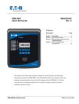
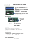
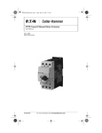
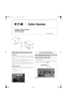
Instructional Leaflet IL04209002E
Effective July 2010
C441M Motor Insight™ Modbus Communication
Module Product Installation Leaflet
Mounting Instructions
Register Set
To
mount
the
Modbus®
communication
module to the Motor Insight overload relay, first
make sure power is disconnected. Next, align the
communication module with the overload realy,
using the 10-pin header as reference for the
correct
orientation.
Hook
the
lower
tabs
(furthest from the 10-pin header) into the base unit,
and then rotate the communication module into
position until a click is heard.
Please see the Motor Insight User Manual,
MN04209001E for details on the Modbus register
space.
Quick Start
The following parameters configure the Modbus
communication interface. Parameters may be set
either with the user interface or through the Modbus
port. For more information on setting the parameters
via the user interface, please reference user interface
section of Motor Insight User Manual MN04209001E.
TABLE 1. MODBUS PARAMETERS
MODBUS
UI
MODBUS
PARAMETER INTERFACE REGISTER
Modbus
Operation
431
Address
Parameter
Modbus Baud Advanced
432
Rate
Parameter
P.00
Modbus Parity Advanced
442
Parameter
P.01
Comm Loss Advanced
441
Behavior ¹
Parameter
P.04
Comm Loss ----
440
Timeout
Configuration Advanced
402
Reset
Parameter
P0.05
DEFAULT
NOTES
1
Must be unique
and between 1
and 247.
Requires power
cycle reset to
take effect.
8 data bits, even
parity, 1 stop bit.
Requires power
cycle reset to
take effect.
Default is 1 for
fault.
19.2K
8,e,1
1
2000
2 seconds.
0, no reset Set to 1 to give
asserted
power cycle
reset (soft
reset). Clears
after reset
asserted.
¹ To eneable comm loss behavior, write 136 to register 400.
TABLE 2. SPECIFICATIONS
PARAMETER
VALUE
Mode
Slave mode only
Modbus Address/Slave
1-247 (0 for broadcast) (1 is default)
Address
Baud Rate
1200 Bd to 115k Bd (19,200 Bd default)
Byte Characteristics
8-bit. Even parity (default), 1 stop bit (default)
Options:
8-bit, no parity, 2 stop bits
8-bit, odd parity, 1 stop bit
Slave Response to Master10 ms plus the time it takes to transmit
response (when applicable)
Commands Supported
0x01 Read Coils
0x02 Read Discrete Inputs
0x03 Read Holding Registers
0x04 Read Input Register
0x05 Write Single Coil
0x06 Write Single Register
0x0F Write Multiple Coils (15)
0x10 Write Multiple Registers (16)
0x17 Read/Write MUltiple Registers (23)
0x2B/0x0E Read Device Identification Get
Device Identity (43/14)
Protocol Supported
Modbus RTU
Electrical Signaling
RS-485 (ANSI/TIA/EIA-485), Two-wire
Checksum
CRC 16-bit 0x8005 (for CRC-CCITT 0x1021)
Max. Data Signaling Error 2% in reception, 1% in transmission
Accepted
Max. Number of Devices 32 (1 unit load per RS-485); Note: line
polarization will reduce max. # of devices by 4.
LED Indication
Frame Reception (Rx) - Yellow
Frame Transmission (Tx) - Yellow
Max. cable Length
Dependent on baud rate, cable characteristics
(gauge, capacitance or impedance), number
of loads. 4000 ft. max. theoretical. Reference
MODBUS-IDA over Serial Line Specification
and Implementation Guide and EIA-485 for
details.
Max. Number of
Unlimited
Writes to Non-Volatile
Memory
Connector Style
Screw terminal
Network Topology
Two-wire Modbus, Daisy-chain and/or repeater
Line Polarization
Not required. Reference MODBUS over Serial
Line Specification and Implimentation Guide
and EIA-485 for more information.
Instructional Leaflet IL04209002E
Effective July 2010
TABLE 3. MODBUS FIELD WIRING
PIN #
CIRCUIT
EIA-485
NAME
C441M Motor Insight™ Modbus Communication
Module Product Installation Leaflet
TABLE 5. EMC/EMI
RECOMMENDED
WIRE COLOR
DESCRIPTION
DESCRIPTION
SPECIFICATION
1
Common
C/C’
Grey
Signal and optional power
supply com.
Radiated
Emissions
IEC 60947-4-1 - Table 15, EN 55011 (CISPIR 11) Group 1,
Class A, ISMEquipment for Industrial, Scientific, and
Medical Equipment. 30 MHz to 1000 MHz.
2
D1
B/B’
Yellow
Transceiver teminal 1, V1
Voltage, Data + (V1>V0 for
binary 1 [OFF] state)
Conducted Emissions
IEC 60947-4-1 - Table 14, EN 55011 (CISPIR 11) Group 1,
Class A, ISM Equipment for Industrial, Scientific, and
Medical Equipment. 0.15 MHz to 30 MHz.
ESD Immunity
IEC 60947-4-1, +/-8 kV air, +/-4 kV contact.
Radiated Immunity
IEC 60947-4-1
10V/m 80 MHz - 1000 MHz
80% Amplitude Modulated 1 kHz sine wave.
Conducted Immunity
IEC 60947-4-1
140 dBuV (10V RMS) 150kHz - 80 MHz
Fast Transient Immunity
IEC 60947-4-1 and IEC 6100-4-4 +/-2kV
Surge Immunity
IEC 60947-4-1
IEC 61000-4-5 Class 3.
Voltage Variations Immunity
IEC 60947-4-1
30% dip @100 ms
60% dip @10 ms
>95% interrupt @5 ms
Power Freq. Magnetic Field
Immunity
IEC 60947-4-1
30 A/m, 50Hz
3
N/C
4
DO
A/A’
Brown
5
Transceiver terminal 0, V0
Voltage, Data - (V0>V1 for
binary 0 [ON] state)
N/C
Reference:
User Manual MN04209001E.
TABLE 4. ENVIRONMENTAL SPECIFICATIONS
DESCRIPTION
SPECIFICATION
Ambient Operating
Temperature
-20°C to 50°C
Storage Temperature
-40 to 85°C
Operating Humidity
5% to 95% non-condensing
Pollution Degree per IEC
60947-1
3
Overvoltage Category per
UL® 508
III
Altitude
2000m
Vibration
3g in any direction
Shock
15g in any direction
Eaton Corporation
Electrical Sector
1000 Cherrington Parkway
Moon Township, PA 15108
United States
877-ETN-CARE (877-386-2273)
Eaton.com
© 2008 Eaton Corporation
All Rights Reserved
Printed in USA
Publication No. IL04209002E
July 2010 Rev.002
PowerChain Management is a registered
trademark of Eaton Corporation.
All other trademarks are property of their
respective owners.