1
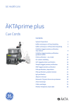
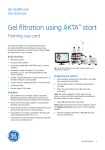
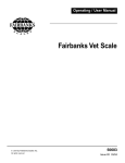
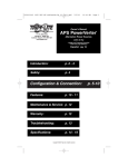
A
M
E
R
S
H
A
M
B
I
O
S
GradiFrac
C
™
User Manual
56-1006-08
Edition AF
I
E
N
C
E
S
Important user information
Reading this entire manual is
recommended for full
understanding of the use of
this product.
w
The exclamation mark within an equilateral triangle is
intended to alert the user to the presence of important
operating and maintenance instructions in the
literature accompanying the instrument.
Warranty and Liability
Amersham Biosciences AB guarantees that the product
delivered has been thoroughly tested to ensure that it
meets its published specifications. The warranty
included in the conditions of delivery is valid only if
the product has been installed and used according to
the instructions supplied by Amersham Biosciences AB.
Amersham Biosciences AB shall in no event be liable for
incidental or consequential damages, including
without limitation, lost profits, loss of income, loss of
business opportunities, loss of use and other related
exposures, however caused, arising from the faulty
and incorrect use of the product.
Trade marks
Should you have any comments on this manual, we
will be pleased to receive them at:
GradiFrac™, HiLoad®, HiTrap®, RESOURCE® and
Superloop™ are the exclusive trade marks of
Amersham Biosciences AB. In view of the risk of trade
mark degeneration, it is respectfully suggested that
authors wishing to use these designations refer to their
trade mark status at least once in each article.
Amersham Biosciences AB
S-751 82 Uppsala
Sweden
Copyright© 1997
Amersham Biosciences AB
Amersham Biosciences AB reserves the right to make
changes in the specifications without prior notice.
All rights reserved. No part of this publication may be
reproduced, stored in a retrieval system or transmitted
in any form or by any means, without permission in
written form from the company.
Contents
1.
2.
3.
4.
5.
Introduction .....................................................................................3
Description .......................................................................................4
2.1 Front Panel..............................................................................4
2.2 Rear panel ...............................................................................5
2.3 Power supply...........................................................................6
2.4 Tube racks ...............................................................................6
2.5 Delivery arm and tube sensor ..................................................7
2.6 Solenoid valves ........................................................................7
2.7 Delivery tubing........................................................................8
Accessory equipment ........................................................................9
3.1 System components .................................................................9
3.2 Rack........................................................................................9
3.3 Pumps .....................................................................................9
3.4 Mixer ....................................................................................10
3.5 Solenoid valves ......................................................................10
3.6 Injection valve .......................................................................10
3.7 Recorder................................................................................10
3.8 Monitor.................................................................................11
Unpacking and assembly ................................................................12
4.1 Unpacking .............................................................................12
4.2 Assembling tube racks ...........................................................12
4.3 Mounting the bowl................................................................15
4.4 Inserting tubes .......................................................................16
4.5 Adjusting the delivery arm.....................................................16
4.6 Fitting the delivery tubing......................................................16
4.7 Mounting solenoid valves......................................................16
4.8 System mounting ...................................................................17
4.9 System connection .................................................................18
4.10 Tubing connections................................................................20
4.11 Starting the system ................................................................21
4.12 Turning the system off ...........................................................21
Setup and programming..................................................................22
5.1 GradiFrac Main menu ...........................................................22
5.2 Setup menu............................................................................22
5.3 Calibrating the pump ............................................................25
5.4 Program Method menu .........................................................26
5.5 Programming a new method..................................................26
5.6 Editing an existing method ....................................................29
5.7 Documenting methods...........................................................30
5.8 Method examples ..................................................................30
6. Operation .......................................................................................33
6.1 Manual operation..................................................................33
6.2 Method-controlled operation ................................................35
7. Maintenance ...................................................................................37
8. Troubleshooting..............................................................................38
9. Technical specifications...................................................................40
10. Accessories......................................................................................41
11. Ordering information .....................................................................42
Appendix: System configuration............................................................44
Index.....................................................................................................46
1. Introduction
1. Introduction
GradiFracTM (Code No. 18-1993-01) from Amersham Biosciences AB combines
the functions of gradient programmer and programmable fraction collector
for standard chromatography applications. It forms the basic unit of
GradiFrac System, which includes GradiFrac, Pump P-1, Monitor UV-1,
Recorder REC 102, Valve IV-7, Switch Valve PSV-50 and a mounting rack.
Gradients are generated using a single pump and a switch valve.
Easy-to-use programming allows automatic gradient formation for preprogrammed separation methods. Up to ten methods can be stored in the
instrument memory. Stored methods are retained in memory even when the
power is switched off. GradiFrac can also be used in manual control mode,
and manual adjustments can be made while a method is running.
GradiFrac can be programmed to collect fractions based on time, volume or
drop count. Fractions can also be collected in a peak detection mode when a
suitable monitor is connected. Tube racks accommodate tubes with diameter
10-18 mm and length 50-180 mm.
3
2. Description
2. Description
2.1 Front Panel
The front panel consists of an alphanumerical LCD display window and a
keyboard with membrane keys.
Fig. 1. GradiFrac front panel.
The keyboard is divided into numerical keys and function keys.
2.1.1 Numerical keys
are used for entering values during programming and manual control.
2.1.2 Function keys
are used during both programming and operation. The main functions are
briefly summarized below, and are described in more detail as required in
the appropriate sections.
Step through the control and programming menus. You can use the arrow
keys whenever the display shows an up, down or double arrow.
ENTER
end
feed
tube
Y/N
pause
4
Enters parameters as shown in the display during programming and manual
control.
Acknowledges error messages.
Stops manual operation.
Interrupts method operation before the method is completed. Finishes work
in the various menu blocks and returns to the main menu.
Advances the fraction collector one position (except when GradiFrac is
paused) The tube feed is delayed according to the Setup value for Delay UV
to Frac if the flow rate is not zero.
Switches between display of Yes and No answers to prompts in manual
control and method programming. Pressing ENTER accepts the displayed
answer.
Pauses all manual or method-controlled operation without ending the
method. Pressing continue restarts operation.
2. Description
hold
con
tinue
2.2 Rear panel
Holds method time or volume and holds gradient at the current
concentration. All other functions continue uninterrupted. Pressing continue
restarts the gradient.
Resumes normal operation from the paused or held state.
The power supply switch and electrical connections for accessories are
mounted on the rear panel.
Fig. 2. GradiFrac rear panel.
The rear panel switches and connectors are described briefly below. See
Section 4.9 for more details of connecting accessories to GradiFrac.
ON/OFF
Tube
sensor
Power
Mixer
Frac
Aux
Switch
Pump
When the red circle is visible the instrument is off.
Connector for tube sensor and drop counter (mounted on the
delivery arm).
Connector for 24 V DC power supply. A power conversion unit
for use with 100-240 VAC mains is supplied with GradiFrac.
Connector for supplying power to Amersham Biosciences Mixer 0.6 ml.
Connector for flow diversion valve (PSV-50), which diverts flow
between fraction tubes and waste.
Connector for auxiliary valve (PSV-50).
Connector for gradient switch valve (PSV-50).
15-pin D-SUB connector for control of pump (e.g. Pump P1 or
HiLoad Pump P-50).
Recorder
Start/Stop Signal for starting and stopping the recorder chart.
Event mark Event marker signal, activated at fraction collector start and at
each tube change.
GND
Ground for start/stop and event marker signals.
Grad 1V
Signal for recording the gradient (0-1 V corresponding to
0–100% B).
A GND
Analogue ground for the gradient signal.
5
2. Description
Monitor
Input
DIP switches to set the monitor signal range. The switches should
be set to correspond to the full-scale output from the monitor
(Figure 3).
Input connector from the monitor. The monitor signal is used for
peak detection.
➔
➔
➔
➔
➔
➔
Range
Fig. 3. DIP switch settings for monitor output voltages.
2.3 Power supply
GradiFrac uses a 24 V DC power supply, eliminating the need for fuses or
circuit breakers in the instrument. A power conversion unit for use with
100-240 VAC mains is supplied with GradiFrac.
The power conversion unit must be placed in a dry place.
Note: GradiFrac should only be connected to a power supply recommended
by Amersham Biosciences.
2.4 Tube racks
Fraction tubes are held in racks which fit into the bowl of GradiFrac. Three
standard racks are available:
1.
12 mm rack for 175 tubes, diameter 12 mm.
2.
18 mm rack for 95 tubes, diameter 10-18 mm.
3.
30 mm rack for 40 tubes, diameter 30 mm.
GradiFrac is delivered with the 18 mm rack. The other racks are available as
optional accessories.
The 12 mm and 18 mm racks can be assembled to accommodate tube
lengths 50-85 mm or 85-180 mm. The 30 mm rack can be assembled to
accommodate tube lengths 30-50 mm, 50-85 mm or 85-180 mm. For
correct operation, all tubes in a collection sequence must be of the same size.
See Section 4.2 for details of tube rack assembly.
Note: In the 18 mm rack, tubes longer than 100 mm should have diameters
at least one tenth of the length. Otherwise pressure from the delivery
arm can force the tube toward the centre of the rack.
Tubes are arranged in the rack in a counter-clockwise spiral from the
outside edge in to the centre. Tube positions are numbered on the tube
holders.
Custom tube racks can be made from block styrofoam or by drilling tube
holders from plastic plates of the appropriate size. It is important that the
angle and distance between tubes are not too great so that tube changes can
be made smoothly.
During operation, the bowl and tube rack are turned by the rubber-covered
drive sleeve at the side of the GradiFrac base. The position at which the rack
stops for each tube is determined by the tube sensor on the delivery arm (see
below), so that the rack will not stop in an empty tube position. A safety
feature stops collection automatically if rotation of the bowl is obstructed.
6
2. Description
2.5 Delivery arm
and tube
sensor
The delivery arm carries the delivery tubing, tube sensor and drop counter.
The cable (carrying both tube sensor and drop counter signals) is connected
to the Tube sensor contact on the rear panel or GradiFrac.
Fig. 4. Delivery arm and tube sensor.
The delivery arm has three stationary positions. At rest it is located over the
waste collector in the centre of the bowl. It can also be drawn gently
outwards to two positions beyond the radius of the bowl for unhindered
access to the tube rack. During operation, the delivery arm is tensioned
inwards and rests with the tube sensor against the edge of a tube (where
present). The height of the arm can be adjusted with the lock knob on the
support rod.
The tube sensor detects the presence of tubes in the tube rack. If a tube is
missing, the delivery arm will swing inwards until a tube is detected or the
centre position is reached. Note that the spiral tube sequence will be
interrupted in such circumstances.
The red sensor control switch at the end of the delivery arm adjusts the tube
sensor for large or small diameter tubes. Turn the switch to the smaller
marking for tubes in the 12 mm rack, and to the larger marking for tubes in
the 18 and 30 mm racks.
The delivery tubing is inserted into the tubing holder. A tubing length guide
is provided midway along the upper side of the delivery arm to help in
positioning the end of the delivery tubing correctly with respect to the drop
counter. This guide is a small hole with a white ring. See Section 4.6 for a
description of how to fit the delivery tubing correctly.
2.6 Solenoid
valves
The supplied solenoid valves PSV-50 may be connected to the ports marked
Frac and Switch on the rear panel of GradiFrac, with the following
functions:
Frac
Diverts flow to waste when fractions are not being collected
(fraction size is set to 0).
Switch Switch valve for gradient formation.
7
2. Description
The port marked Aux is for an optional third solenoid valve, e.g. for threebuffer systems and for automatic application of large sample volumes.
Solenoid valve PSV-50 has three outlets:
IN
NO
Normally open
NC
Normally closed
See Figures 13 and 14 for tubing connections to the valves.
2.7 Delivery
tubing
8
0.8 mm i.d. tubing is recommended and is supplied with GradiFrac. Tubing
connector/M6 (Code No. 19-1993-50) is used for connection.
3. Accessory equipment
3. Accessory equipment
3.1 System
components
Recommended components for use together with GradiFrac are listed
below. Some typical system arrangements are illustrated in the appendix.
Component
Recommended models
Rack
GradiFrac System Rack
Pumps
Peristaltic Pump P-1
HiLoadTM Pump P-50
Solenoid valves
PSV-50 for gradient formation
PSV-50 for flow diversion
PSV-50 for sample application or three-buffer systems
(optional)
Manual valves
IV-7
Mixer
Mixer 0.6 ml
Monitor
UV-1
Recorder
REC 102
Columns
Prepacked HiLoadTM and HiTrapTM columns
(see Chapter 10)
3.2 Rack
A rack (Code No. 18-1993-05) is available for convenient mounting of
system components.
3.3 Pumps
Recommended pumps for use with GradiFrac are Pump P-1 for flow rates
0-8.3 ml/min and HiLoad™ Pump P-50 for flow rates up to 50 ml/min.
Other pumps may also be used provided that the pump speed is frequencycontrolled.
GradiFrac controls pump speed by a pulsed output signal with frequency
range 0-4 kHz. The programmable flow rate range is 0–99.9 ml/min. The
pump calibration constant can be entered directly if known, or the pump
can be calibrated by collecting a measured volume. See Section 5.3 for
details of pump calibration.
Connection to GradiFrac: 15 pin D-SUB.
Recommended cable: Communication cable (Part No. 19-6005-02).
9
3. Accessory equipment
Pump connector pin assignments:
Pin no
Function
(1-6)
7
(8)
9
10
(11)
12
13
14
15
(Not used in GradiFrac)
0 V (ground)
(Not used in GradiFrac)
Pump busy
Pump operable
(Not used in GradiFrac)
Pump control
Frequency from pump (for calibration)
Frequency to pump (pump speed)
0 V (ground)
As long as GradiFrac is switched on, the pump is controlled entirely from
GradiFrac. To use the controls on the pump itself, switch off the power to
GradiFrac or disconnect the pump communication cable.
3.4 Mixer
Amersham Biosciences Mixer 0.6 ml is suitable for most applications using
GradiFrac. For high flow rates (above 8 ml/min), Mixer 6.0 ml is recommended.
Mixer 0.6 ml is connected to the Mixer port on the rear panel of GradiFrac,
which supplies power to the mixer (24 V AC, 50 Hz). The mixer operates as
long as GradiFrac is turned on.
Mixer 6.0 ml cannot be supplied with power from GradiFrac and requires a
separate power source.
3.5 Solenoid
valves
Solenoid valve PSV-50 should be used with GradiFrac. PSV-50 may be
connected to the ports marked Frac, Switch and Aux on the rear panel of
GradiFrac, with the following functions:
Frac
Diverts flow to waste when fractions are not being collected
(fraction size is set to 0).
Switch Switch valve for gradient formation.
Aux
Optional third switch valve, e.g. for three-buffer systems and for
automatic application of large sample volumes.
3.6 Injection valve
Injection Valve (IV-7) is recommended for sample application. If desired, a
system may be configured with the auxiliary switch valve as a sample
application valve (see Appendix).
3.7 Recorder
Recorders such as Amersham Biosciences REC 101 and REC 102 as well as
other recorders are suitable for use with GradiFrac.
The recorder is connected to the port(s) marked Recorder on the rear panel
of GradiFrac. Use the Recorder Cable packed in the GradiFrac box
(Code No. 56-1136-67). (The ordering number for the Recorder Cable is
18-1107-88.) The port connections have the following functions:
Start/Stop Start and stop the recorder chart. The chart drive will operate
as long as the flow rate is not zero.
10
3. Accessory equipment
Event marker signal, activated at fraction collector start and
markat each tube change. The signal is a short (50 ms) pulse.
GND
Ground for start/stop and event marker signals.
For two-channel recorders, GradiFrac supplies a signal
corresponding to the buffer gradient:
Grad 1V Signal for recording the gradient (0–1 V corresponding to
0–100% B).
A GND Analogue ground for the gradient signal.
Event
3.8 Monitor
Monitor UV-1 is recommended for use with GradiFrac. The output from the
monitor is connected to the Monitor +, – ports on the rear panel of
GradiFrac to supply a signal for peak detection functions. Recommended
cable: Signal cable (Part No. 19-6006-01).
The Range switches on the rear panel of GradiFrac should be set to the fullscale output from the monitor (10 mV for Monitor UV-1).
The output from the monitor should be connected separately to the recorder
and to GradiFrac. There is no output from GradiFrac for the monitor signal.
An adaptor cable for connecting UV-1 to both GradiFrac and a recorder is
supplied with GradiFrac.
11
4. Unpacking and assembly
4. Unpacking and
assembly
4.1 Unpacking
Unpack the GradiFrac carefully and check the contents of the carton against
the included packing list. Inspect each item for damage that may have
occurred during transit. Save the packing material and carton for later use.
4.2 Assembling
tube racks
Tube racks are assembled in the GradiFrac bowl from some or all of tube
holder, tube guide and tube support (Figure 5). Details of assembly differ
according to the length and diameter of the tubes.
tube support
rib
L-shaped
cutout
tube guide
single
cutout
tube holder
Fig. 5. Tube rack components.
Components of the tube rack are positioned in the bowl by engaging the
cutouts (either single or L-shaped) on the edge of the component with the
ribs on the inside of the bowl. This ensures that the different components
are correctly aligned with each other.
12
4. Unpacking and assembly
4.2.1 Tube racks 12 mm and 18 mm.
Tube lengths 50-85 mm
L-shaped cutout
single cutout
same
tube number
Fig. 6. Assembly of 12 mm and 18 mm tube racks for 50-85 mm tubes.
13
4. Unpacking and assembly
Fit the tube support, using the L-shaped cutouts. The support should be
seated in the lower position in the bowl with the circular marks on the
underside.
Fit the tube guide in the bowl with the tube numbers facing up, using the
single cutouts. The guide should come to rest approximately 1 cm above the
tube support.
Fit the tube holder in the bowl with the tube numbers facing up, using the
single cutouts, ensuring that tube position 1 is directly above tube position 1
in the tube guide. The tube holder is held in position by the indentations in
the ribs of the bowl. Check that the tube holder is level and firmly seated
before filling it with tubes.
Tube lengths 85-180 mm
L-shaped
cutout
same
tube
number
Fig. 7. Assembly of 12 mm and 18 mm tube racks for 85-180 mm tubes.
Do not use the tube support.
Fit the tube guide in the bowl with the tube numbers facing up, using the
L-shaped cutouts. The guide should be seated in the lower position in the
bowl.
Fit the tube holder in the bowl with the tube numbers facing up, using the
single cutouts, ensuring that tube position 1 is directly above tube position 1
in the tube guide. The tube holder is held in position by the indentations in
the ribs of the bowl. Check that the tube holder is level and firmly seated
before filling it with tubes.
14
4. Unpacking and assembly
4.2.2 Tube rack 30 mm.
Tube lengths 30-50 mm
Tube holder, 30 mm
Tube guide, 30 mm
Tube guide, 18 mm
single
cutouts
Fig. 8. Assembly of 30 mm tube racks for 30-50 mm tubes.
Fit the tube guide from the 12 or 18 mm rack, using the single cutouts. Fit
the tube support on top of the tube guide to give the extra height necessary
when using short tubes.
Fit the 30 mm tube guide, using the single cutouts.
Fit the tube holder in the top of the bowl with tube position 1 directly above
tube position 1 in the tube guide.
Tube lengths 50-85 mm
Fit the tube support using the L-shaped cutouts. The support should be
seated in the lower position.
Fit the tube guide using the single cutouts.
Fit the tube holder in the top of the bowl with tube position 1 directly above
position 1 in the tube guide.
Tube lengths 85-180 mm
Do not use the tube support.
Fit the tube guide in the bowl with the tube numbers facing up, using the
L-shaped cutouts. The guide should be seated in the lower position in the
bowl.
Fit the tube holder in the bowl with the tube numbers facing up, ensuring
that tube position 1 is directly above tube position 1 in the tube guide. The
tube holder is held in position by the indentations in the ribs of the bowl.
Check that the tube holder is level and firmly seated before filling it with
tubes.
4.3 Mounting the
bowl
Move the delivery arm out to the second stop. Place the bowl containing the
rack over the central spindle. Pull the spring-loaded drive sleeve away from
the bowl so that the bowl drops into position.
15
4. Unpacking and assembly
The bowl should come to rest with a gap of approximately 1 cm between
the bottom of the bowl and the GradiFrac base.
4.4 Inserting tubes
Insert sufficient collection tubes into the rack beginning at position 1.
Ensure that the tubes are pushed down as far as possible. All tubes in one
collection sequence must be of the same length and diameter and there
should be no empty spaces.
4.5 Adjusting the
delivery arm
1. Move the arm by lifting it a little so that the tube sensor comes to rest
against a tube in the outer row.
2. Loosen the lock knob on the column.
3. Adjust the height of the arm so that the tube sensor is about 5 mm below
the top of the tubes and tighten the lock knob.
4. Rotate the rack anti-clockwise by hand until the sensor comes to rest
against the tube in position 1. Ensure that the red sensor switch is
correctly set for the tube diameter (to the smaller marker for 12 mm
racks and to the larger marker for 18 and 30 mm racks).
4.6 Fitting the
delivery tubing
1.
2.
3.
4.
Cut the end of the delivery tubing cleanly at 90°.
Lift out the tubing holder from the delivery arm and loosen the nut.
Fit the delivery tubing through the tubing holder.
Place the tubing holder over the length guide hole. Push the tubing
through the holder until it reaches the bottom of the length guide, then
tighten the nut on the tubing holder. This ensures that drops are formed
in the correct position with respect to the drop counter.
5. Fit the tubing holder into the delivery arm.
4.7 Mounting
solenoid valves
Screw the valve holder to the back of the delivery arm using the screws
provided. Attach the flow diversion valve PSV-50 to the valve holder
(Figure 9).
Fig. 9. Mounting the flow diversion valve.
16
4. Unpacking and assembly
4.8 System
mounting
Sections 4.8-4.10 describe assembly of GradiFrac System. System
components are listed in Section 3.1. A separate System Installation Guide is
available.
1. Prepare GradiFrac as described in Sections 4.2-4.7.
2. Attach the solenoid valve for gradient formation to the valve bracket. If
an auxiliary valve is used, attach this to the same valve bracket alongside
the gradient valve (Figure 10).
Fig.10. Fitting the gradient valve to
the valve bracket. The auxiliary
valve can be fitted to the same
bracket.
3. Assemble the rack as described in the instructions provided.
4. Prepare the other components for use as described in the respective User
Manuals.
5. Place the system components in the rack as shown in Figure 11.
17
4. Unpacking and assembly
Mixer
P-1
IV-7
UV-1
control unit
PSV-50
gradient
valve
GradiFrac
UV-1
optical
unit
REC 102
Fig. 11. Placing the system components in the rack.
4.9 System
connection
w
18
Connect components electrically to GradiFrac as described below
(Figure 12).
Use a screwdriver to fit the green connectors supplied with GradiFrac to the
valve, recorder and monitor cables that are to be connected to GradiFrac
rear panel. Valve cables have no polarity and may be connected either way
round. Connect the monitor cable with the polarity shown on GradiFrac
rear panel and recorder cables as shown in Figure 12.
All sockets on the rear panel must have their respective green connectors
fully inserted to avoid the risk of electrostatic discharge (ESD).
4. Unpacking and assembly
Fig. 12. Electrical connections.
4.9.1 Tube sensor
Connect the tube sensor cable from the delivery arm to the Tube sensor
contact on the rear panel of GradiFrac. (This cable may already be
connected on delivery).
4.9.2 Pump
Connect the Remote contact on the pump to the Pump contact on the rear
panel of GradiFrac.
4.9.3 Valves
Connect the flow diversion valve to the Frac port on the rear panel of
GradiFrac.
Connect the gradient valve to the Switch port on the rear panel of
GradiFrac.
Connect the auxiliary valve, if used, to the Aux port on the rear panel of
GradiFrac.
4.9.4 Mixer
Connect Mixer 0.6 ml to the Mixer port on the rear panel of GradiFrac.
19
4. Unpacking and assembly
4.9.5 Recorder
Connect the recorder to the three-pin port marked Recorder (Start/stop,
event mark, GND) and the two-pin port marked Recorder (GRAD 1V, A
GND) on the rear panel of GradiFrac, using the special Recorder Cable
packed in the GradiFrac box (Code No. 56-1136-67). (The ordering number
for the Recorder Cable is 18-1107-88.)
Connect the 15-pin D-SUB connector to the port on the rear panel of the
recorder, and the red and black pin connectors to channel 2 (red) on the top
of the recorder.
Set the red switch on the recorder (voltage selector for channel 2) to 1 V.
Note: Chart speed must be set locally on the recorder. The int/ext button
on REC 102 should be in position int. The Rec on/off button should
be in position on.
4.9.6 Monitor
Set the DIP switch on the rear panel of GradiFrac (see Section 2.2) to
correspond to the full-scale output from the monitor (10 mV for Monitor
UV-1).
Use the Y-cable supplied with GradiFrac to connect the monitor output to
both GradiFrac and recorder. Connect the monitor output to the Monitor
port on GradiFrac, taking care to match the + and – poles. Connect the
monitor output separately to channel 1 input on the recorder.
Set the blue switch on the recorder (voltage selector for channel 1) to
correspond to the full-scale output from the monitor (10 mV for Monitor
UV-1).
4.9.7 Power supply
Connect the 24 V DC outletfrom the power conversion unit to the Power
socket on the rear panel of GradiFrac. Connect the power conversion unit to
the mains supply. The conversion unit adjusts automatically to mains
voltages in the range 100-240 V AC, 50-60 Hz.
4.10 Tubing
connections
Connect tubing as shown in Figures 13 and 14. Make sure that the tubing
connections to the solenoid valves are made to the correct valve outlets as
shown in Figure 14.
Fig. 13. Connecting tubing to PSV-50.
20
4. Unpacking and assembly
Fig. 14. System tubing connections.
4.11 Starting the
system
Turn on the power to GradiFrac first, then to the other components in the
system.
4.12 Turning the
system off
Turn off the power to the pump and recorder first. If GradiFrac is turned off
while power is still supplied to pump or recorder, these instruments will
start to run according to the settings on the instruments themselves. This
can be particularly important for the pump, since liquid or air may
otherwise inadvertently be pumped through the system.
21
5. Setup and programming
5. Setup and
programming
5.1 GradiFrac
Main menu
The GradiFrac main menu is divided into four blocks:
Main menu
RUN METHOD
Main menu
MANUAL RUN
Main menu
PROGRAM METHOD
Main menu
SETUP
Fig. 15. GradiFrac main menu.
When GradiFrac is first switched on, the Run method option is displayed.
Press the arrow keys to move between menu options.
5.2 Setup menu
The Setup menu block sets general operation parameters. Setup should be
performed when GradiFrac is first installed and whenever parameters need
to be changed.
Current setup parameters apply during manual operation and method
programming. During method-controlled operation, the method base
(time/volume) and fractionation base (time/volume/drop) which were current
at the time of programming apply. All other Setup parameters during
method-controlled operation are those which were last entered.
Note that the method base and fractionation base are defined by those used
in the most recently accessed method (either in Method Run or in Program
method), unless they are actively reset in Setup.
Switch on GradiFrac. After a short interval, the display shows:
Main Menu
Run Method
Press the
key three times until the display shows
Main Menu
Setup
22
5. Setup and programming
Press ENTER to enter the setup block.
Main menu
RUN METHOD
end
METHOD BASE
[time/vol]
Main menu
MANUAL RUN
FRACTIONATE BY
[time/vol/drop]
Main menu
PROGRAM METHOD
CALIBRTN VALUE
[pls/0.1 ml]
ENTER
Main menu
SETUP
PUMP CALIBRATION
PROCEDURE
ENTER
START COLLECTING
ENTER
DELAY UV TO FRAC
[µl]
PRESS [end] TO
STOP COLLECTING
end
MIX VOLUME
[µl]
ENTER COLLECTED
VOLUME [ml]
DROP SYNC ACTIVE
[Y/N]
Fig. 16. The Setup menu block.
5.2.1 Setting the method base
Set the method base with Method base (Figure 16).
Choose time (min) or volume (ml). The chosen base will apply for all
subsequent programming of new methods. Previously stored methods
however retain the method base in which they were programmed.
METHOD BASE
VOLUME (ml) [Y/N]
N
Y
METHOD BASE
TIME (min) [Y/N]
N
Y
Fig. 17. Setting the method base.
5.2.2 Setting the fractionation base
Set the fractionation base with Fractionate by (Figure 16).
Choose time (min), volume (ml) or drops. The chosen base will apply for
manual operation and for all subsequent programming of new methods.
Previously stored methods however retain the fractionation base in which
they were programmed.
23
5. Setup and programming
FRACTIONATE BY
VOLUME (ml) [Y/N]
N
Y
FRACTIONATE BY
TIME (min) [Y/N]
N
Y
FRACTIONATE BY
DROPS (drp) [Y/N]
N
Y
Fig. 18. Setting the fractionation base.
5.2.3 Setting the pump calibration factor
Set the pump calibration factor with Calibrtn value (Figure 16).
The pump calibration factor is the number of pulses required to deliver
0.1 ml from the pump. Enter the value directly if known and press ENTER.
If the calibration factor is unknown, see Section 5.3.
Note that the calibration factor for Pump P-1 depends on the tubing
diameter. You are advised always to perform pump calibration whenever the
tubing is changed.
The pump calibration factor will apply for all subsequent manual and
method-controlled operation until a new value is set.
5.2.4 Setting the monitor-to-collector delay
Set the delay volume between the UV monitor and the fraction collector
with Delay UV to Frac (Figure 16).
Enter the volume of liquid (in µl) in the delivery tubing between the UV
monitor flow cell and the very end of the tubing. This will ensure that event
marks on the UV absorbance trace on the recorder are synchronized with
tube changes. Calculate the delay volume from the length of tubing. The
volume of 0.8 mm i.d. tubing is 50 µl/10 cm.
The delay volume will apply for all subsequent manual and methodcontrolled operation until a new value is set.
5.2.5 Setting the mixing volume
Set the mixing volume with Mix volume (Figure 16).
The mix volume is the total volume (µl) of liquid (buffer A + buffer B)
which passes through the gradient valve during one cycle of operation. The
value for the mix volume together with the flow rate thus determines the
switching frequency of the valve. If the mix volume is too low, the switching
frequency may be too high (the minimum cycle time for valve PSV-50 is
30 ms). If the mix volume is too high, the gradient will be inaccurate at low
flow rates. The mix volume for Pump P-1 is calculated according to the
table below:
24
5. Setup and programming
Pump tubing
i.d. (mm)
Flow rate
range (ml/min)
Mixer
(ml)
Mix volume
(µl)
1.0
0–1
0.6
Mix volume =
54 000
pump calibration factor
2.1
1–4
0.6
Mix volume =
18 000
pump calibration factor
3.1
3–5
0.6
Mix volume =
8 800
pump calibration factor
3.1
5–8
6.0
Mix volume =
18 000
pump calibration factor
The following values are recommended for HiLoad Pump P-50:
Flow rate
(ml/min)
Mixer
(ml)
Mix volume
(µl)
0-5
>5
0.6
6.0
60
600
Note that the mix volume is not the same as the volume of the mixer.
The mix volume will apply for all subsequent manual and methodcontrolled operation until a new value is set.
5.2.6 Setting drop synchronization
Set drop synchronization with Drop sync active (Figure 16).
If drop synchronization is active, tube changes will only occur directly after
a drop is registered by the drop counter, to minimize spillage between tubes.
Drop synchronization operates in all fraction collection modes (time,
volume and drop).
Drop synchronization is only possible at flow rates below 3 ml/min.
The drop synchronization setting will apply for all subsequent manual and
method-controlled operation until a new value is set.
5.3 Calibrating the
pump
To calibrate the pump, move to Pump calibration procedure in the Setup
menu (Figure 16) and press ENTER. Follow the steps below:
1. Set the speed on the pump to a value close to the flow rate which will be
used subsequently. For Pump P-1, use the flow rate guide supplied with
the pump.
2. Make sure there are no air bubbles in the pump or delivery tubing.
3. Enter the setup block in the GradiFrac main menu.
4. Press
until the display shows Pump calibration procedure, then press
ENTER to enter the calibration process. The display will show Start
collecting.
5. Place a suitable measuring vessel under the outlet tubing and press
ENTER. The pump will start to operate and the display will show Stop
collecting.
6. Collect a volume large enough for accurate measurement, then press end
to stop collecting. The pump will stop and the display will show Enter
collected volume.
7. Measure the collected volume, enter the value (ml) and press ENTER.
GradiFrac will calculate the calibration factor, and the display will show
the calculated value.
25
5. Setup and programming
8. Press end to return to the main menu or
to continue with the setup
menu.
The calibration factor for HiLoad Pump P-50 is 234 pulses/0.1 ml. Enter
this factor directly in the Setup menu if Pump P-50 is used. Pump calibration
should only be necessary for Pump P-1 and other pumps with unknown
calibration factors.
5.4 Program
Method menu
GradiFrac can store up to 10 methods of 52 breakpoints each.
Main menu
RUN METHOD
end
SELECT METHOD
[0-9] FREE n
Method occupied!
Main menu
MANUAL RUN
CLEAR METHOD
[Y/N]
ENTER
Y = new method
Main menu
PROGRAM METHOD
N = edit method
Main menu
SETUP
CE +
ENTER
EDIT BREAKPOINT
[time/volume]
TIME/VOLUME
CONC %B
TIME/VOLUME
FLOW ml/min
REMOVE CURRENT
BREAKPOINT [Y/N]
continue
TIME/VOLUME
FRACTN
end
TIME/VOLUME
VALVE ACTIVE [Y/N]
N
END METHOD
[Y/N]
TIME/VOLUME
PEAK COLLECT [Y/N]
Y
TIME/VOLUME
SLOPE %/ml
Y
ALARM AT
time/volume
SHOW CONC %B ON
REC OUT [Y/N]
Fig. 19. The Program method control block.
Each holds settings for all method parameters. During programming, the
default settings for a new breakpoint are taken from the previous existing
breakpoint in the method.
5.5 Programming
a new method
5.5.1 Selecting a method number
Choose Program Method in the main menu (Figure 15) and press Enter.
Enter the number of the method to program. GradiFrac shows the number
of the lowest empty method in the window, and suggests the most recently
used number as default.
If the method number is occupied, GradiFrac responds with the message
Method occupied!
To choose a new method number, press end to return to the main menu.
To clear the existing method, press ENTER to acknowledge the message,
then answer Y to the Clear method prompt. Answering N here allows you
to edit the method (see Section 5.6).
26
5. Setup and programming
5.5.2 Entering breakpoints
A method consists of a series of breakpoints which define changes in one or
more control parameters. Methods are programmed on a time or volume
base, according to the current setting in Setup (see Section 5.2). The first
breakpoint must be at time/volume 0.0. An alarm can be set anywhere in the
method, e.g. to alert the operator for manual sample application or to signal
the end of the method.
Note: If FRACTN, VALVE ACTIVE or PEAK COLLECT breakpoints are
to be programmed within a gradient, then these breakpoints should
be added after the gradient programming is completed. This avoids
the need to calculate the exact value for CONC %B within the
gradient. By programming as described above, GradiFrac will
perform the calculation automatically.
Move through the program method menu with the arrow or ENTER keys,
setting breakpoint parameters as required. If several breakpoints have been
set, you can move up and down through the breakpoints, changing
parameters as required.
5.5.3 Programming gradient shape
Set the concentration of buffer B with CONC %B (Figure 19).
Two breakpoints with different values for concentration of B will create a
linear gradient from the first to the second value over the interval between
the breakpoints. For example, the following breakpoints give a gradient
from 25 to 45 %B, starting at 5 minutes and extending over 10 minutes:
TIME
CONC %B
5.0 min
25
TIME
CONC %B
15.0 min
45
Two gradient breakpoints separated by 0.1 ml or min will create a step
gradient with an immediate change in buffer B concentration. For example,
the following breakpoints cause an abrupt change from 25 to 45 %B at time
5 min.
TIME
CONC %B
4.9 min
25
TIME
CONC %B
5.0 min
45
5.5.4 Programming flow rate
Set the flow rate with Flow ml/min (Figure 19). A method cannot be
programmed with zero flow rate.
Any changes in flow rate are made instantaneously at the breakpoint (time
or volume) where the new value is requested.
27
5. Setup and programming
5.5.5 Programming fraction size
Set the fraction size with Fraction [min/ml/drop] (Figure 19).
The fraction base (time, volume or drops) is determined by the current
setting in Setup (see Section 5.2).
As long as the fraction size is set to 0, the flow diversion valve will divert
effluent to waste.
5.5.6 Programming the auxiliary valve
Control the auxiliary valve where used with Valve active [Y/N] (Figure 19).
The auxiliary valve is connected to the Aux port. Enter Y to activate the
valve and N to deactivate the valve. The current setting is indicated by Y or
N in the instruction prompt.
5.5.7 Programming peak collection
Set peak collection with Peak collect [Y/N] (Figure 19).
Enter Y to activate peak collection. The fraction size must be set to >0 for
peak collection to be activated. This may be done in the same breakpoint as
that in which peak collection is activated.
If peak collection is activated, enter the threshold slope for peak detection as
Slope %/ml. Values may be set from 1 to 99 %/ml. The fraction collector
will change tubes whenever the slope exceeds the set value. The peak end is
determined automatically by GradiFrac. The set fraction size applies both
within and between peaks.
The following procedure is recommended for determining a suitable slope
value:
1. Use a previous chromatogram from an identical run to determine the
slope %/ml (see Figure 19). Peak collection is not recommended with an
unknown sample.
2. Perform a blank run with the chosen setting to check that tube changes
do not occur as a result of baseline disturbances. If unwanted tube
changes occur, set a higher slope value and repeat the run.
AU
0.5
0.4
Monitor FSD = 0.5 AU
Slope at peak start = 0.05 AU/ml
Slope at peak start = 10% FSD
0.3
Peak collect slope = 10%/ml
0.2
Peak
start
0.1
0
0.05 AU
1 ml
0
5
Fig. 20. Determining the slope value for peak collection (%/ml).
28
10
Elution vol (ml)
5. Setup and programming
5.5.8 Ending the method
The method will end at the last breakpoint. If you require a period of
constant parameters at the end of the method, enter a final breakpoint with
the same parameters as the penultimate breakpoint (see the examples in
Section 5.8).
When all breakpoints have been entered, press end to end method
programming and answer Y to the End method prompt.
5.5.9 Programming an alarm
Set an alarm with Alarm at (Figure 19).
If you want an alarm to sound during or after the method, enter a non-zero
value here. For example, entering Alarm at 1 min will sound an alarm
1 minute after the method is started.
5.6 Editing an
existing
method
To edit an existing method, choose Program method from the main menu.
Select the number of the method and press enter.
GradiFrac responds with the message:
Method occupied!
Press ENTER to acknowledge the message, then answer N to the Clear
method prompt. You may now edit the breakpoints in the existing method.
Use the arrow keys at the Edit breakpoint prompt to scroll through the
existing breakpoints, or enter the time or volume for an existing breakpoint
to move directly to that breakpoint.
5.6.1 Inserting a breakpoint
To insert a breakpoint, enter the breakpoint time or volume at Edit breakpoint (Figure 19) and press ENTER. Set the parameter values as required. A
newly entered breakpoint “inherits” default parameter settings from the
closest previous breakpoint in the method.
5.6.2 Changing breakpoint parameters
To change the time or volume for a breakpoint, insert a new breakpoint at
the required time or volume as described in Section 5.6.1, then delete the
unwanted breakpoint as described in Section 5.6.3. You may need to edit
parameter settings for the new breakpoint.
To change other parameters for an existing breakpoint, move to the
required breakpoint, press ENTER, then change the parameters as required.
Remember that all parameters are set at every breakpoint. A new parameter
value must be entered for all breakpoints where it is to apply. This is
particularly important for flow rate and fraction size which are often set
early in a method and apply throughout the method. If for example the flow
rate is changed only at the first breakpoint, the previous flow rate will be
restored at the second breakpoint.
5.6.3 Deleting a breakpoint
To remove an existing breakpoint, move to the required breakpoint and set
the time/volume to 0 (use the CE key to clear the existing value). GradiFrac
will ask you to confirm that the breakpoint should be deleted.
29
5. Setup and programming
5.7 Documenting
methods
The programmed gradient shape for any stored method may be documented
on the recorder when method programming is completed. Set the recorder
chart speed to 10 or 20 mm/s and answer Y to the prompt SHOW CONC
%B ON REC OUT at the end of the Program Method block (Figure 19).
The complete method is recorded in 10 s.
It is important that you make notes of the purpose and structure of methods
stored in GradiFrac. Without these, it is easy to forget the purpose of a
method which is identified by number alone, and it may be difficult to
reconstruct the method if it is accidentally deleted.
The form on page 32 suggests a standard for recording method notes and
breakpoints.
5.8 Method
examples
Example 1 illustrates a simple GradiFrac method for a gradient elution with
a linear gradient from 0 to 60 %B then an instantaneous change to 100 %B.
Peak detection is set to on. The sample is applied manually after 1 minute,
and fraction collection starts at the beginning of the gradient (allowing
25 ml flow-through to run to waste).
100
%B
80
60
40
20
0
0
10
20
30
Fraction collection
40
50
min
Fig. 21. Buffer gradient in the example method.
Table 5-1. Breakpoints for example method 1. Values actively entered for each breakpoint
are shown in bold. Unchanged values are grey.
Time
Conc %B
0.0
0
5
0
N
N
-
Start method
5.0
0
5
0.5
N
Y
5
Start gradient, start fractions
29.9
60
5
0.5
N
Y
5
End gradient
30.0
100
5
0.5
N
Y
5
Start column wash
44.9
100
5
0.5
N
Y
5
End column wash
45.0
0
5
0
N
N
-
End fractions
start re-equilibration
50
0
5
0
N
N
-
End method
Alarm at 1 min
30
Flow Fractn Valve Peak Slope Comment
Alert for sample application
5. Setup and programming
Note the final breakpoint at 50 minutes which ensures that the method
continues for 5 minutes after the concentration of B is reduced to 0.
Example 2 shows illustrates a method with the same gradient as above, but
using an auxiliary valve for sample application (see system configuration
in Appendix). In example 2, fractions are collected between 10 and
20 minutes, starting and stopping within the gradient. Note how these
breakpoints are entered after the gradient is programmed, allowing
GradiFrac to calculate the value for CONC %B.
Table 5-2. Breakpoints for example method 2. Values actively entered for each breakpoint
are shown in bold. Unchanged values are grey.
Time
Conc %B Flow Fractn Valve
Peak
Slope
Comment
0.0
0
5
0
N
N
-
Start method
1.0
0
5
0
Y
N
-
Start sample application
2.0
0
5
0
N
N
-
End sample application
5.0
0
5
0
N
N
-
Start gradient
29.9
60
5
0
N
N
-
End gradient
30.0
100
5
0
N
N
-
Start column wash
44.9
100
5
0
N
N
-
End column wash
45.0
0
5
0
N
N
-
Start re-equilibration
50.0
0
5
0
N
N
-
End method
10.0
12
5
0.5
N
Y
5
Start fractions
20.0
36
5
0
N
N
-
End fractions
Alarm at 50 min
Signal method end
31
5. Setup and programming
Method no:.....................................................................
Author:.............................
Column type: ...............................................................
Auxiliary valve used?
Setup parameters:
Method base: time ❑ volume ❑
Pump calib. value: ......................
Mix vol:.........................................
Fractionate by: time ❑ volume ❑ drop ❑
Delay UV to frac: ..................................
Drop sync active: .................................
Notes:
Breakpoints:
Time/volume
32
Conc %B
Flow
Fractn
Valve
Peak
Slope
Comment
Date:........................
6. Operation
6. Operation
6.1 Manual
operation
To control GradiFrac manually without using a preprogrammed method,
choose Manual Run in the main menu and press ENTER.
Main menu
RUN METHOD
Main menu
MANUAL RUN
end
ENTER
MANUAL
CONC %B
MANUAL
FLOW ml/min
Gradient is
already on
Main menu
PROGRAM METHOD
MANUAL
FRACTN
Main menu
SETUP
MANUAL
GRADIENT
(if gradient
already running)
ENTER
TARGET
CONC %B
ENTER
MANUAL
VALVE ACTIVE [Y/N]
MANUAL
PEAK COLLECT [Y/N]
REACH TARGET
AFTER [ml/min]
Y
MANUAL
SLOPE %/min
Fig. 22. The Manual Run control block.
Use the arrow keys to move through the menu options, setting parameters
as required. Settings take effect as soon as the instruction is confirmed with
ENTER. You can change parameters at any time during manual control,
with the exception of the gradient. Gradient parameters can only be
changed
1) if there is no gradient running, or
2) if the system is paused or held.
To end manual control, press end.
6.1.1 Setting a gradient
Set a constant concentration of buffer B with CONC %B (Figure 22). The
concentration will apply as soon as you press ENTER. To change the
concentration instantaneously (step gradient), simply enter a new value.
To set a gradient, move to GRADIENT (Figure 22), press ENTER, then
enter the target concentration of buffer B and the time or volume after
which the target is to be reached. The base is determined by the current
method base setting in Setup (see Section 5.2). For example, the following
entries start a gradient from the current concentration to 70% B over a
period of 10 minutes:
TARGET
CONC %B
70
33
6. Operation
REACH TARGET
AFTER min
10.0
If a gradient is already running, GradiFrac will respond with the message
Gradient is
already on
The display changes to CONC %B after 3 s. Press pause or hold followed
by ENTER to stop the gradient and enter new parameters.
A gradient can only be started if the pump is running. If a gradient is
requested when no flow has been set, GradiFrac will respond with the
message
No Flow
and return to the beginning of the manual run menu.
The display indicates the current gradient direction with the symbols:
/
increasing % B
–
constant (isocratic) % B
\
decreasing % B
6.1.2 Setting flow rate
Set the flow rate with Flow [ml/min] (Figure 22). The pump will start (or
change speed if already started) when you press ENTER.
6.1.3 Setting fraction size
Set the fraction size with Fraction [min/ml/drop] (Figure 22). The fraction
base (time, volume or drops) is determined by the current setting in Setup
(see Section 5.2). The fraction size will apply as soon as you press ENTER.
As long as the fraction size is set to 0, the flow diversion valve will divert
effluent to waste.
6.1.4 Operating the auxiliary valve
Operate the auxiliary valve where used with Valve active [Y/N] (Figure 22).
The auxiliary valve is connected to the Aux port. Enter Y to activate the
valve and N to deactivate the valve. The current setting is indicated by Y or
N in the instruction prompt.
6.1.5 Setting peak collection
Set peak collection with Peak collect [Y/N] (Figure 22).
Enter Y to activate peak collection. The peak collection function is
explained on p. 28.
34
6. Operation
6.2 Methodcontrolled
operation
This section describes the use of GradiFrac for method-controlled runs. It is
assumed that GradiFrac has been installed as described in Chapter 4 and
that at least one method has been programmed. Method programming is
described in Section 5.4.
6.2.1 Running a method
Fig. 23. The Run method control block.
1. Fill the tube rack with tubes, starting at position 1, and adjust the
delivery arm so that the tube sensor rests against the outer side of tube
no. 1.
2. Choose Run method from the main menu and press ENTER:
3. Enter the number of the method to run (0-9: the numbers of programmed
methods are displayed) and press ENTER to start the method. If you
enter the number of a method which has not been programmed,
GradiFrac will respond with the message Method is empty. Press ENTER
to acknowledge and select another method number.
4. When the method is finished, GradiFrac will display the message Method
is completed. Press end to return to the main menu. Press ENTER twice
to re-run the method.
6.2.2 Interrupting a method
There are three ways to interrupt a method:
pause stops method operation but does not end the method. Press continue
to resume method operation.
hold holds method time/volume and stops gradient changes but continues
to operate the pump and fraction collector. Press hold again to
display the accumulated volume. Press continue to resume gradient
formation.
end
interrupts the method with the prompt End method Y/N. Entering Y
terminates the method. Entering N resumes method operation.
35
6. Operation
6.2.3 Examining current method status
During method operation, the arrow keys can be used to scroll through
display of the current method status.
The following information is displayed:
Method no.
Method
status
2 RUN
Elapsed method
time or volume
7.8 ml
CONC %B
Possible program
direction
23
Current parameter
value
Parameter currently
displayed
6.2.4 Manual control during method operation
The parameter values in method status display may be replaced with new
values to modify method operation.
A parameter which is changed manually continues to apply until it is reset
by a breakpoint with a value different from that originally programmed in
the method. For example, consider a method with breakpoints at 0, 5 and
10 minutes with flow rate 2, 2 and 4 ml/min respectively:
0.00 FLOW 2.0 ml/min
5.00 FLOW 2.0 ml/min
10.00 FLOW 4.0 ml/min
If the flow rate is changed manually to 3 ml/min after 2 min, this value will
continue to apply until the breakpoint at 10 min.
Gradients can only be changed in Hold or Pause.
36
7. Maintenance
7. Maintenance
GradiFrac should be cleaned thoroughly after use. Inadvertently spilled
liquid should not be allowed to dry on the instrument and the delivery arm
should always be returned to its central position over the bowl when not in
use.
No regular maintenance is required.
The surfaces of GradiFrac may be wiped with mild aqueous cleaning
solutions or with ethanol.
Maintenance of the power supply should be carried out by authorised
Amersham Biosciences personnel only.
Maintenance of other components in GradiFrac System is described in the
respective manuals.
37
8. Troubleshooting
8. Troubleshooting
The table below lists messages which may appear on the GradiFrac display,
with explanations and suggested actions.
If other error messages appear for which the corrective action is not
obvious, contact technical service.
Message
Cause
Action
Tube pos error
Tube sensor active due to
jammed rack.
Check for obstructions to rack movement and
remove them.
Tube sensor broken
Contact Amersham Biosciences service engineer.
No more tubes.
Fill rack with more tubes.
Rack movement jammed
Check for obstructions to rack movement and
remove them.
Delivery arm in stand-by
position.
Position the delivery arm correctly.
Method is empty!
Attempt to run method
without instructions
Choose a different method number.
Warn: Check that
tubepos is OK
Tube sensor between tubes
(only at start of run).
Position the GradiFrac bowl so that a tube is
directly under the flow outlet.
No Flow
Attempt to start a manual
gradient or program a
breakpoint with no flow.
Set a flow rate manually or as the first
breakpoint in the method.
Stop gradient in HOLD
or PAUSE
Attempt to change CONC
%B during a running
gradient.
Press hold or pause and stop the gradient first.
Recalibrate pump or
flow too high
Too high flow rate or
incorrect calibration factor
Set a lower flow rate or recalibrate the pump.
Recalibrate pump or
flow too low
Too low flow rate or
incorrect calibration factor
Set a higher flow rate or recalibrate the pump.
Warning: Switch valve
too fast
Mix volume too low for
requested CONC %B at
this flow rate.
Set a higher mix volume. (The warning may be
ignored at CONC %B close to 0 or 100 in a
gradient).
Switch cycle time too
fast
Flow rate too high or mix
volume too low.
Set a lower flow rate or higher mix volume.
No more tube available
38
8. Troubleshooting
Message
Cause
Action
Gradient is already on
Attempt to change CONC
%B during a running
gradient (manual mode).
Wait until the gradient is complete, or press
pause or hold followed by ENTER to stop the
gradient.
Warning: Pump is not
operable
Attempt to start pump
failed.
Check that the pump is switched ON and that
the communication cable is properly connected.
Press ENTER then continue to ignore the
message (pump must be controlled separately).
Pump OverPresssure
The pressure limit for the
pump has been reached
(HiLoad Pump P-50 only).
Find and correct the cause of the overpressure.
Tubing or column may be blocked, or the flow
rate may be too high for the column.
Pump RUN is not
pressed
The RUN button on the
pump is not pressed
(HiLoad Pump P-50 only).
Press the RUN button on the pump.
Too short time between
feeds
Flow rate too high or
fraction size too small.
Reduce the flow rate or set a larger fraction size.
No fraction size
Attempt to use peak
collection with no fraction
size.
Set a fraction size before activating peak
collection.
No drops, check sensor
No drops detected (drop
sync mode or drop
fraction base only).
Check that buffer drops from the outlet. Clean
the drop sensor.
If the error persists, contact Amersham Biosciences
service or run without drop sync and drop counting.
Continuous flow, check
sensor
No drops detected due to
too high flow rate or dirty
drop sensor.
Reduce the flow rate or clean the drop sensor.
If the error persists, contact Amersham Biosciences
service or run without drop sync and drop counting.
Method memory is full
Attempt to program more
than 52 breakpoints in a
method.
Reduce the number of breakpoints in the
method.
No alarm after end of
method
Attempt to set an alarm
later than method
completion.
Set the alarm within the method. (Use extra
breakpoints with zero flow rate to extend the
method time).
Bad drop sensor or not
connected
Drop sensor cable not
connected or dirty drop
sensor (setup mode only).
Check the drop sensor connection or clean the
drop sensor.
Endpoint missing, edit
your method
The method consists of
only one breakpoint.
Add breakpoints to the method.
39
9. Technical specifications
9. Technical
specifications
GradiFrac
Programming base
Programming capacity
Memory protection
Pump control
Gradient formation
ml or min
10 separate methods, 52 breakpoints each
EEPROM
Remote for Pump P-1 and HiLoad Pump P-50
Single pump and switch valve
Fraction collection
Time base
Volume base
Drop base
Tube change time
Rack capacity
Event mark
Flow diverter
Monitor input range
Recorder control
Valve control
Mixer
Power supply
Power consumption
Dimensions (w x d x h)
Weight
Environment
Safety standards
EMC
Safety
40
0.1–99.9 min
0.1–99.9 ml
1–999 drops
0.3–0.6 s (tube rack 18 mm)
95 tubes, rack 18 mm
50 ms contact closure
Solenoid valve PSV-50
0–10 mV, 0–100 mV, 0–1000 mV
Controls REC 101 and REC 102
3 outports for Solenoid Valve PSV-50 (switch valve, flow
diverter, auxiliary)
0.6 ml
24 V DC Power Supply for 100–240 VAC, 50-60 Hz
15 VA maximum
290 x 300 x 390 mm
3.9 kg
4 to 40 °C, 20-95% relative humidity,
84-106 kPa (840-1060 mbar) atmospheric pressure
This product meets the requirement of the EMC Directive
89/336/EEC through the harmonized standards EN 50081-2
(emission) and EN 50082-1 (immunity)
Note: This is a class A product. In a domestic
environment this product may cause radio interference
in which case the user may be required to take
adequate actions.
Note: The declaration of conformity is valid for the instrument
when it is :
• used in laboratory locations
• used in the same state as it was delivered from
Amersham Biosciences AB except for alteration
described in the User Manual
• used as ”stand alone” unit or connected to other CE
labelled Amersham Biosciences products or other
products as recommended
This product meets the requirement of the Low Voltage
Directive (LVD) 73/23/EEC through the harmonized standard
EN 61010-1.
10. Accessories
10. Accessories
Please order accessories according to the designation and code numbers
given below. Refer to Figure 24 for position number where given.
Fig. 24. GradiFrac accessories.
41
10. Accessories
11. Ordering information
Designation
Code No.
GradiFrac System components
Peristaltic Pump P-1
Monitor UV-1, Control and Optical Unit
Flow cell 10 mm
280 nm Filter Kit
Recorder REC 102, 2-channel
Mixer 0.6 ml
Injection Valve IV-7
Sample loops, 1 and 2 ml
Rack
Valve Bracket Kit
Tubing connector/M6 male, pkg/5
Tubing ETFE, 0.8 mm i.d., 1.8 mm o.d., 2 m
Valve Holder Kit
Recorder Cable
Power supply 24 V
18-1110-91
18-1003-66
19-2504-02
19-2433-01
18-1001-43
19-6700-01
19-1996-01
18-5897-01
18-1993-05
19-1994-50
19-1993-50
19-7435-01
19-1994-70
18-1107-88
18-1032-06
Optional
HiLoad Pump P-50
Mixer 6 ml 110 V
Mixer 6 ml 220 V
Solenoid valve PSV-50
Accessories (refer to Figure 10-1)
Tube holder/guide, 12 mm
Tube holder/guide, 18 mm
Tube holder/guide, 30 mm
Tube support
Bowl
Tube rack complete, 12 mm
Tube rack complete, 18 mm
Tube rack complete, 30 mm
Tube spring, metal (for 18 mm holder/guide)
Valve PSV-50
Valve holder kit
Tubing holder
Tube sensor kit
Funnel
Funnel tubing 12/8, 250 mm
Drive sleeve
Spiral cable
Sensor positioning kit
Accessories available but not illustrated
Drop Counter Kit
Communication cable, Pump P-1
Signal cable, UV-1
Tube holder kit 8/11 mm
42
19-1992-01
18-3500-01
18-3501-01
19-1994-01
Position no.
1
2
3
4
5
6
7
8
9
10
11
12
13
14
15
16
19
20
19-7242-02
19-8689-02
18-1124-68
18-3054-02
18-3051-03
19-8684-03
18-3050-03
18-1124-67
19-6057-01
19-1994-01
19-6069-01
18-6464-01
19-7815-02
19-6044-01
18-3020-01
19-6067-02
19-8638-01
18-6470-01
18-1012-05
19-6005-02
18-0577-01
18-8522-01
10. Accessories
Designation
Code No.
Green connector 4-pole female
Green connector 2-pole female
254 nm Filter Kit
405 nm Filter Kit
Inlet tubing
Assorted sample loops (25, 50, 100, 200, 500 ml)
SuperloopTM 10 ml (together with Pump P-50)
SuperloopTM 50 ml (together with Pump P-50)
Clamp holder, pkg/5
18-0863-01
19-8629-01
19-2432-01
19-4724-01
19-4448-01
18-0404-01
19-7585-01
19-7850-01
18-1032-03
Gel filtration columns
HiLoad 16/60 Superdex 75 prep grade
HiLoad 26/60 Superdex 75 prep grade*
HiLoad 16/60 Superdex 200 prep grade
HiLoad 26/60 Superdex 200 prep grade*
HiLoad 16/60 Sephacryl S-100 HR
HiLoad 26/60 Sephacryl S-100 HR
HiLoad 16/60 Sephacryl S-200 HR
HiLoad 26/60 Sephacryl S-200 HR
HiLoad 16/60 Sephacryl S-300 HR
HiLoad 26/60 Sephacryl S-300 HR
17-1068-01
17-1070-01
17-1069-01
17-1071-01
17-1165-01
17-1194-01
17-1166-01
17-1195-01
17-1167-01
17-1196-01
Ion exchange columns
HiLoad 16/10 Q Sepharose HP
HiLoad 26/10 Q Sepharose HP*
HiLoad 16/10 S Sepharose HP
HiLoad 26/10 S Sepharose HP*
HiLoad 16/10 Q Sepharose FF
HiLoad 26/10 Q Sepharose FF*
HiLoad 16/10 S Sepharose FF
HiLoad 26/10 S Sepharose FF*
RESOURCE Q
1 ml
RESOURCE Q
6 ml
RESOURCE S
1 ml
RESOURCE S
6 ml
17-1064-01
17-1066-01
17-1065-01
17-1067-01
17-1060-01
17-1062-01
17-1061-01
17-1063-01
17-1177-01
17-1179-01
17-1178-01
17-1180-01
Hydrophobic interaction columns
HiLoad 16/10 Phenyl Sepharose HP
HiLoad 26/10 Phenyl Sepharose HP*
17-1085-01
17-1086-01
*HiLoad pump P-50 is recommended for best performance with these columns.
Affinity chromatography columns
HiTrap Protein A, 5x1 ml
HiTrap Protein A, 1x5 ml
HiTrap Protein G, 5x1 ml
HiTrap Protein A, 1x5 ml
HiTrap Heparin, 5x1 ml
HiTrap Heparin, 1x5 ml
HiTrap Chelating, 5x1 ml
HiTrap Chelating, 1x5 ml
HiTrap Blue, 5x1 ml
HiTrap Blue, 1x5 ml
HiTrap NHS-activated, 5x1 ml
HiTrap NHS-activated, 1x5 ml
17-0402-01
17-0403-01
17-0404-01
17-0405-01
17-0406-01
17-0407-01
17-0408-01
17-0409-01
17-0412-01
17-0413-01
17-0416-01
17-0417-01
43
Appendix, System configurations
Appendix
System configurations
GradiFrac System, two-valve configuration with Pump P-1.
44
Appendix, System configurations
GradiFrac System, two-valve configuration with HiLoad Pump P-50.
GradiFrac System, with auxiliary valve for sample application.
45
Index
Index
A
accessories
connection ..............................................5,18
ordering information .................................42
adjusting the delivery arm ..............................16
alarm..............................................................29
arrow keys .......................................................4
assembling tube racks
12 mm racks..............................................13
18 mm racks..............................................13
30 mm racks..............................................15
automatic sample application.....................8, 10
auxiliary valve............................................8, 10
connection .................................................19
manual control ..........................................34
mounting ...................................................17
programming.............................................28
B
bowl mounting...............................................15
breakpoints ....................................................26
changing parameters..................................29
deleting......................................................29
inserting.....................................................29
C
calibrating pumps...........................................25
cleaning..........................................................37
connecting accessories ......................................5
connections
electrical ....................................................18
tubing ........................................................20
continue key...............................................5, 35
custom tube racks ............................................6
46
D
delay UV to frac .............................................24
delivery arm .....................................................7
delivery tubing
fitting.........................................................16
recommended ..............................................8
display
method status ............................................36
display messages.............................................38
display window ................................................4
documenting methods ....................................30
drop counter ....................................................7
drop synchronization .....................................25
E
editing a method ............................................29
electrical connections .....................................18
end key.......................................................4, 35
ENTER key......................................................4
event mark .....................................................11
example methods ...........................................30
F
feed tube key ....................................................4
fitting delivery tubing .....................................16
flow diversion.................................................28
flow diversion valve....................................7, 10
connection .................................................19
mounting ...................................................16
flow rate
manual setting ...........................................34
programming.............................................27
flow rate range .................................................9
fraction size
manual setting ...........................................34
programming.............................................28
fractionation base...............................22, 23, 28
front panel .......................................................4
function keys....................................................4
Index
I
injection valve ................................................10
interrupting a method ....................................35
method number
selecting for programming .........................26
methods
documenting..............................................30
examples....................................................30
interrupting ...............................................35
manual intervention...................................35
programming.............................................26
running methods........................................35
status .........................................................36
mix volume ....................................................24
mixer..............................................................10
connection .................................................19
monitor ..........................................................11
connection ...........................................11, 20
monitor range ......................................6, 11, 20
monitor-to-collector delay ..............................24
mounting the bowl .........................................15
mounting valves .............................................16
K
keyboard ..........................................................4
N
numerical keys .................................................4
L
linear gradient
manual ......................................................33
programming.............................................27
P
pause key ...................................................4, 35
peak collection
manual control ..........................................34
programming.............................................28
threshold slope ..........................................28
power conversion unit......................................6
power supply....................................................6
connection .................................................20
power switch....................................................5
program method menu...................................26
programming an alarm...................................29
programming auxiliary valve..........................28
programming flow rate...................................27
programming fraction size..............................28
programming gradients ..................................27
G
gradient valve.............................................7, 10
connection .................................................19
mounting ...................................................17
gradients
manual alterations .....................................34
manual control ..........................................33
programming.............................................27
GradiFrac System .............................................9
configuration .............................................44
mounting ...................................................17
H
HiLoad Pump P-50 ..........................................9
hold key .....................................................5, 35
M
main menu .....................................................22
maintenance ...................................................37
manual auxiliary valve control .......................34
manual flow rate setting .................................34
manual fraction size setting ............................34
manual gradients............................................33
manual operation ...........................................33
manual peak collection...................................34
manual run menu ...........................................33
method base .............................................22, 23
47
Index
programming peak collection .........................28
pump calibration
factor.........................................................24
procedure ..................................................24
pump calibration factor
for HiLoad Pump P-50 ..............................26
pump connector ...............................................9
Pump P-1 .........................................................9
pumps
connection .................................................19
control.........................................................9
recommended ..............................................9
R
rack..................................................................9
component placing ....................................18
rear panel .........................................................5
recorder..........................................................10
chart speed ................................................20
connection .................................................20
recorder start/stop ..........................................10
run method menu...........................................35
running a method...........................................35
S
sample application valve ................................10
setup menu.....................................................22
setup parameters ............................................22
slope for peak collection.................................28
solenoid valves ...........................................7, 10
connection .................................................19
mounting .............................................16, 17
outlets..........................................................7
tubing connections.....................................20
48
specifications
GradiFrac ..................................................40
step gradient
manual ......................................................33
programming.............................................27
system components ..........................................9
system configuration ......................................44
system shut-down...........................................21
system start ....................................................21
T
three-buffer systems ...................................7, 10
troubleshooting ..............................................38
tube racks.........................................................6
assembly ....................................................12
components ...............................................12
tube sensor .......................................................6
connection .................................................19
tube sensor switch ............................................7
tubing connections .........................................20
tubing holder....................................................7
tubing length guide.....................................7, 16
V
valves
see solenoid valves
W
waste collector .................................................7
Y
Y/N key............................................................4
Printed in Sweden by TK i Uppsala, June 1997