1
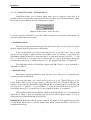
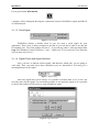
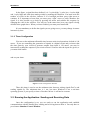
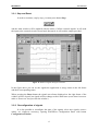
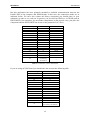
User Manual Version 1.0 LICENSING AND INTELLECTUAL PROPERTY ISSUES WinXSPort Version 1.0, 1-Jun-1999 WinXSPort is available at no cost for non-profit purposes. * WinXSPort Not-for-profit User License Agreement 1. You may copy and distribute copies of WinXSPort or copies of the source code for WinXSPort in any medium provided that you appropriately give credit to the authors and keep intact all intellectual property and disclaimer notices. 2. You may modify your copy of WinXSPort, but you may not distribute modified versions of WinXSPort. You may distribute patches to the original WinXSPort as separate files along with the original WinXSPort. 3. You may not charge anything for copies of WinXSPort beyond a fair estimate of the cost of media and computer/network time required to make and distribute the copies. 4. Incorporation of WinXSPort or any portion thereof into commercial software, distribution of WinXSPort forprofit, or use of WinXSPort for other for-profit purposes requires a special agreement with the authors. Please, contact Ignacio de Miguel at [email protected] 5. The authors of WinXSPort and Universidad of Valladolid assume absolutely no responsibility for the use or misuse of WinXSPort. In no event shall the authors of WinXSPort or Universidad de Valladolid be liable for any damages resulting from use or performance of WinXSPort. WinXSPort has been registered as intellectual property of the authors: Francisco A. Lago García, Gonzalo Martín de Mercado Pérez, T. Paloma Ortega Camarero, and Ignacio de Miguel Jiménez. XESS Corporation is granted the right to distribute this software. Intellectual Property of the Authors, 1999 Permission to use, copy, modify, and distribute this software and its documentation for any non-commercial purpose and without fee is hereby granted, provided that · the above notice appear in all copies · both the above notice and this permission notice appear in supporting documentation THIS SOFTWARE IS PROVIDED "AS IS" WITHOUT REPRESENTATION OR WARRANTY OF ANY KIND, EITHER EXPRESSED OR IMPLIED, INCLUDING WITHOUT LIMITATION, ANY REPRESENTATIONS OR ENDORSEMENTS REGARDING THE USE OF, THE RESULTS OF, OR PERFORMANCE OF THE SOFTWARE, ITS APPROPRIATENESS, ACCURACY, RELIABILITY, OR CORRECTNESS. THE ENTIRE RISK AS TO THE USE OF THIS SOFTWARE IS ASSUMED BY THE USER. IN NO EVENT WILL THE AUTHORS OR THE UNIVERSIDAD DE VALLADOLID BE LIABLE FOR ANY DAMAGES, DIRECT, INDIRECT, INCIDENTAL OR CONSEQUENTIAL RESULTING FROM ANY DEFECT IN THE SOFTWARE, EVEN IF THE AUTHORS OR THE UNIVERSIDAD DE VALLADOLID HAVE BEEN ADVISED OF THE POSSIBILITY OF SUCH DAMAGES. IF YOU DO NOT ACCEPT THESE TERMS YOU MUST CEASE AND DESIST USING THIS SOFTWARE IMMEDIATELY. TABLE OF CONTENTS 1. WELCOME TO WINXSPORT 1.0 ................................................................................................................. 1 1.1 MAIN FEATURES OF WINXSPORT 1.0 ............................................................................................................ 1 1.2 REQUIREMENTS ............................................................................................................................................. 1 2. INTRODUCTION TO THE PARALLEL PORT........................................................................................... 2 2.1 BASE ADDRESS .............................................................................................................................................. 2 2.2 REGISTERS ..................................................................................................................................................... 2 3. WINXSPORT 1.0: THE APPLICATION ....................................................................................................... 4 3.1 CONFIGURING WINXSPORT ........................................................................................................................... 5 3.1.1 WinXSPort Configuration Panel........................................................................................................... 5 3.1.2 Timer Configuration ............................................................................................................................. 9 3.2 RUNNING THE APPLICATION: SENDING AND RECEIVING DATA ...................................................................... 9 3.2.1 Step and Reset ..................................................................................................................................... 11 3.2.2 Reconfiguration of signals .................................................................................................................. 11 3.3 SAVE AND LOAD .......................................................................................................................................... 12 4. EXAMPLE: CONTROL OF A COUNTER.................................................................................................. 13 5. HELP ................................................................................................................................................................ 15 5.1 HELP FILE .................................................................................................................................................... 15 5.2 HELP IN THE APPLICATION ........................................................................................................................... 17 6. INSTALL / UNINSTALL................................................................................................................................ 17 7. FAQS ................................................................................................................................................................ 17 8. KNOWN PROBLEMS.................................................................................................................................... 19 9. THANKS TO…................................................................................................................................................ 20 10. ABOUT US …................................................................................................................................................ 20 11. REFERENCES .............................................................................................................................................. 21 12. APPENDIX A: CONNECTION SCHEMES............................................................................................... 21 WinXSPort User Manual 1. Welcome to WinXSPort 1.0 WinXSPort lets you establish communication with an XS Board or a digital circuit through the Parallel Port of your Computer. You will be able to easily test your designs by using a Windows application. In this manual, you will discover how to use the application WinXSPort, the different possibilities it offers and interesting comments that can help you to solve some of your problems while using it. WinXSPort has been developed by a group of students at the College of Telecommunication Engineers (ETSIT) at the University of Valladolid (Spain). Hopefully, you will find this program useful. 1.1 Main features of WinXSPort 1.0 • It allows communication with XS Boards from XESS Corporation (http://www.xess.com/FPGA), and other external circuits. • It has got a Graphical User Interface. • It works on Windows'95/98/NT. • It supports different port addresses. • You can send signals to the board and read signals from it. • You may select and give meaningful names to the pins used. • Stimulus signals can be set in two ways: − Interactive mode: you may change the signal applied on a pin by pressing a button. − Defined signals: you may define a timing diagram (e.g. my signal X should be high 5 steps, low 3 steps, and so on). Your signals will change according to that diagram. • The signals you sent to the board, and read from it, will be displayed on the screen. • You can store the configuration and the stimulus in a file and load it later to repeat automatically the stimulus sent to the board. 1.2 Requirements • Windows 95/98/NT. • DriverLINX Port I/O Driver must be installed in your computer. This driver is provided without charge by Scientific Software Tools, Inc. (http://www.sstnet.com). You can find a copy at XESS Corp. website: (http://www.xess.com/FPGA/port95nt.exe) • You should configure your parallel port in SPP mode. 1 WinXSPort User Manual 2. Introduction to the Parallel Port A very common technique to connect a PC with electronic circuits is using the Parallel Port, as it offers inputs and outputs for data which are compatible with TTL levels. Then, it is really useful to control digital circuits with a PC and be able to read data generated by the circuit. The Parallel Port is usually placed in the back side of a computer. The Parallel Port connector is typically a 25-pin female connector, type D (DB-25). There are several specifications for the parallel port. Some of them are: • • • SPP (Standard Parallel Port): It is the original specification, being the one this document refers to. You should set your port to this mode in order to use WinXSPort. EPP (Enhanced Parallel Port) ECP (Extended Capabilities Port). The configuration of your parallel port can be changed using BIOS. You may find more information about the different specifications at [Peacock]. 2.1 Base address You can use several registers or read/write ports to control the Parallel Port. These registers are placed in fixed memory positions. A Parallel Port is usually assigned one of these address ranges: BASE ADDRESS RANGE COMMENTS 0x3BC 0x378 0x278 0x3BC - 0x3BF 0x378 - 0x37F 0x278 - 0x27F It is not often used nowadays Usually used for LPT1 Usually used for LPT2 Table 1: Parallel Port address and ranges First of all, you should know the base address for the Parallel Port you are going to use. • If you are using Windows 95, it is easy to know this address following the sequence: Start → Settings → Control Panel → System → Device Manager → Ports → Printer Port (LPTx) → Resources. And there you have it… • If you are using Windows NT you can check it using BIOS. 2.2 Registers There are three 8-bit registers (or ports) which offer interesting operations for communication with the Parallel Port: 2 WinXSPort User Manual 1. Data Register: It is placed at the base address of the port and it is used to send data from the computer to an external peripheral by setting the voltage level of 8 of the pins in the DB-25 connector. 2. Status Register: It is placed at Base address + 1, and it is used to make the computer read data from an external peripheral. It reads the voltage level of 5 of the pins in the connector. 3. Control Register: It is placed at Base address + 2. Another 4 pins that can be used to send data to an external peripheral. For example, if you want to send control signals to an external digital circuit, you can use data or control register to do it, setting bits D0 to D7 of the data register or bits C0 to C3 of the control register. If you are going to receive data from a peripheral, you can do it by reading bits S3 to S7 of the status register. In the figure below you can see which bit in each register controls which pin in a DB25 female connector. For instance, when you write ‘1’ at bit 0 ot data register (D0), you will have ‘1’ at pin 2 of the connector. Pins controlled by the Data Register Pins controlled by the Status Register Pins controlled by the Control Register Note: Pins 18 to 25 must be connected to GND. Figure 1: DB-25 female connector. Correspondence between pins and registers (after [Harries]). In case you need further information about the parallel port and how to make applications interfacing the parallel port, you should have a look to [Peacock], [Harries] and [Anderson]. 3 WinXSPort User Manual 3. WinXSPort 1.0: the Application WinXSPort lets you work with the Parallel Port of a computer, sending and receiving information from the different pins. It is especially designed so that you can send and receive data from an XS40 board1 [Xess, VandenBout], but you can also control other devices. It is advisable to read the introduction to the Parallel Port of this manual before you use this application. WinXSPort is very easy to use. First of all, you have to run the application. You can do it by double-clicking on the WinXSPort icon and you will see the main window. Figure 2: WinXSPort Main Window Then, it is necessary to configure the pins, that is, to select which pins you are going to use and work with. Just press button Configuration Window to make the WinXSPort Configuration Panel appear and set your own configuration. This process is explained with more detail in section 3.1.1. 1 It should work with XS95 and XSP boards too. 4 WinXSPort User Manual Then, it is time for the application to be run, that is, to start sending and receiving data. Pressing button Stimulus Control Window another window will appear. There, it is possible to change the values of the signals in each step and send them with button Step. The application will run step by step, letting you see the state of each signal in the main window. This process will be explained in section 3.2. 3.1 Configuring WinXSPort You should configure WinXSPort before using it: you have to indicate the Parallel Port address in your PC, select the application working mode and the pins you are going to use. You must do it in the WinXSPort Configuration Panel. You may also configure the time elapsed between sending data to the external circuit and reading the output from it. That period can be set by pressing the Timer Configuration button. 3.1.1 WinXSPort Configuration Panel First of all, you have to indicate the Parallel Port address in your PC, select the application working mode, the pins you are going to use. You may even define the stimulus you are going to apply. All these tasks can be done in the WinXSPort Configuration Panel. 5 WinXSPort User Manual Figure 3: WinXSPort Configuration Panel 3.1.1.1 Port Address The default port address is 0x378, but it is also possible to change it in case your application is going to be run in a machine whose Parallel Port has been assigned another address. Figure 4: Parallel Port Address You are given the possibility to select “Other” address, so you must be very careful with the one you write as it is going to be the base address for your next operations with Parallel Port. 6 WinXSPort User Manual 3.1.1.2 Parallel Port Mode / XS Board Mode WinXSPort allows you to choose which mode you are going to work with. It is possible to have an application running in Parallel Port Mode or in XS Board Mode. Thus, first of all, you must indicate it in the configuration window. Figure 5: XS Board Mode / Parallel Port Mode If you are using an XS Board, be sure this mode of operation is selected so that signals can reach the board in the correct status. • Parallel Port Mode This mode of operation should be used for those cases when it is necessary to connect the port with an arbitrary circuit (not an XS Board). If you use this mode, you control and read the level of the DB-25 pins, that is, what you see on your display is what you have at the DB-25 pins. For instance, if you select the WinXSPort signals D0 and D3 to send data and S7 to read data, and you write D0 = ‘1’ and D3 = ‘0’, you will have ‘1’ at pin 2 of the connector and ‘0’ at pin 3. If the output data of the external circuit drives pin 11 of the connector to ‘0’, the program will show ‘0’ at signal S7. The connection between WinXSPort signals and DB-25 pins is set as indicated in Appendix A, Table 2. • XS Board Mode This mode of operation should be used for those cases when you are connecting the parallel port with an XS Board. If you use this mode, you control and read the level of the FPGA/CPLD pins of the board, that is, what you see on your display is what you have at the FPGA/CLPD pins. For instance, if you select the WinXSPort signals D0 and D3 to send data and S7 to read data, and you write D0 = ‘1’ and D3 = ‘0’, you will have ‘1’ at pin 44 of the PLD and ‘0’ at pin 45. If your design drives pin 75 of the PLD to ‘0’, the program will show ‘0’ at signal S7. The connection between WinXSPort signals and XS Board pins is set as indicated in Appendix A, Table 3. Keep in mind that you will not be able to choose signal C0 as it is connected to the /PROGRAM pin of the FPGAs. IMPORTANT: Remember that if you are using an XS Board in your application you must use XS Board Mode since if you use Parallel Port Mode instead, the FPGA will clear its configuration memory. 7 WinXSPort User Manual If you press button Information, a window will be displayed showing the connection between WinXSPort signals and DB-25 or XS Board pins. 3.1.1.3 Clock Signal Figure 6: Clock Signal WinXSPort defines a default clock in case you need a clock signal for your application. Then, clock is always assigned to pin D0, so you will not be able to use this pin for anything else. The clock changes its state (1 - 0) in each step, that is, when pressing button Step at the Stimulus Control. Therefore: 1 step = 1 half-cycle. You can choose if you want the clock to start at level 0 or 1. 3.1.1.4 Signal Choice and Signal Definition Now, you have to indicate which signals, and therefore which pins, you are going to work with. Thus, you must select those checkboxes you are interested in. You may give a meaningful name to the signal. Figure 7: Signal choice Once the signals have been chosen, it is possible to define them so as to have the necessary state for the signal. You can define periodic or non-periodic signals as it is possible to choose the number of half-cycles or steps in high/low status. Figure 8: Signal Definition 8 WinXSPort User Manual In the figure, a signal has been defined: it is 3 cycles high, 3 cycles low, 4 cycles high and 1 cycle high, and it has been made periodic by marking the checkbox. You must write the number of cycles in the edit box, indicate if it is low/high and then press right arrow to continue. It is important to know that you must press “right” arrow to really introduce the signal. It is also possible to go back by pressing left arrow and redefine the sequence by changing the value in the edit box. You will see, at the same time, how your signal is being defined in the graph above. When you have finished, you must press button OK. It is not mandatory to define the signals you are going to use, you may change its status interactively later. 3.1.2 Timer Configuration You can set the minimum allowable time between write/read operations: default is 100 msecs. If you are controlling the generation of signals in a digital circuit and you know that the time spent by your circuit to generate outputs from input is 150 msecs, you may be interested in reading the outputs of your circuit at least 150 msecs after the inputs are given, so you must click button and set your timer. Figure 9: Timer Configuration Window Then, this timer is used to set the minimum time between writing signals Dx/Cx and reading signals Sx. The minimum time is 1 ms., but since Windows is not a real-time operating system, if you specify a timer of less that 100 ms. it will not be accurate. 3.2 Running the Application: Sending and Receiving Data Once the configuration is set, you are ready to run the application and establish communication with the Parallel Port, sending and receiving data to/from it. You only have to press button Stimulus Control Window: 9 WinXSPort User Manual Then, a new window will appear where you can interactively change signals status. Figure 10: Stimulus Control Window In the stimulus control dialog, you can see the signals you are working with (only those associated with Dx and Cx but not the ones associated with Sx) and their current and next status (on/off). Pressing the Switch button you may change the signal status interactively, if it has not been defined. If you have defined a non-periodic signal that lasts N cycles, this switch button will not be enabled until cycle N+1. This button is not enabled for periodic signals. Pressing the Repeat Sequence button, the signal will follow the sequence previously defined. For example, you may have defined a signal to as: 1 1 0 1 0, and every time you press this button it will follow that sequence. This button is not enabled for periodic signals. 10 WinXSPort User Manual 3.2.1 Step and Reset In order to continue, step by step, you must press button Step and the main window will be updated with the status of all the selected signals. It will send the input to the external circuit or board and, afterwards, it will read the output provided. Figure 11: Different signals during the execution In the figure above you can see the signals the application is using: names in the left frame and their corresponding status. When pressing the Reset button the signals waveforms displayed on the right frame of the window will be cleared, but signals will not change to their initial state (reset doesn’t mean to make a “Power-on” but just clear the window). 3.2.2 Reconfiguration of signals It is also possible to reconfigure the state of the signals, select new signals, remove others, etc. whenever necessary, opening WinXSPort Configuration Panel with button Configuration Window 11 WinXSPort User Manual and if you also want to define new signals, you must press button Define and follow indications in 3.1.1.4. 3.3 Save and Load Now, if you want to save your current workspace (your configuration and stimulus history), you can do it by pressing button Save or selecting option Save in the File Menu. And if you want to load a previous workspace you only have to press button Open or select option Open in the File Menu. Thus, the new configuration will be set and the stimulus will be applied. Loading of a file is slow since it repeats all the process, that is, it repeats the stimulus applied to the board/circuit. Imagine that you are testing the design of a filter in an XS Board, and when applying some stimulus (maybe 60 or 70 steps long) it fails. You may save the configuration and stimulus in a file (e.g. filter.sti), then you could redesign your filter, download it to the board, and once it is downloaded you could open the file filter.sti. Thus, the stimulus will be automatically applied to the board so you just have to check whether the results are OK now or not. 12 WinXSPort User Manual 4. Example: Control of a counter We want to implement a counter in an FPGA placed in an XS40 Board. Using Xilinx Foundation Series, our design is: Figure 12: Counter design As said before, this design is going to be implemented in an XS40 Board, thus, we must work in XS Board Mode, and it will be necessary to know which are the connections between the FPGA, the Parallel Port and the DB-25 Connector (Appendix A, table A.2). ⇒ In this design, inputs are: • Clock Signal: Pin 44 of the FPGA is used, which corresponds to input signal D0 of WinXSPort. As we are using Board Mode, when we write ‘1’ in the program, there will also be ‘1’ in pin 44 of the FPGA (idem with 0). • Enable: Pin 47 of the FPGA is used, which corresponds to input signal D3. ⇒ Counter outputs are placed in pins 70, 77, 66 and 69 of the FPGA, which correspond to WinXSPort signals S3, S4, S5 and S6, respectively. So, the configuration we are going to use in WinXSPort is shown in the figure below: 13 WinXSPort User Manual Figure 13: Configuration Panel As said before, we must use both a clock signal (D0) and an enable signal (D3). This one can be defined in this dialog box, pressing Define or change its status interactively later. In the figure below, you can see the different signals. In the outputs, OUT1 is the LSB and OUT4 is the MSB. The counter has performed 0, 1, 2 … 9, … and it began when the enable signal was set to ‘1’. Figure 14: Main window with the outputs given by WinXSPort 14 WinXSPort User Manual 5. Help Apart from this manual, you can also get on-line help for the application. You can access this help by two different means: using the help file provided with WinXSPort or directly from the application. 5.1 Help file You can access help by double clicking on icon “WinXSPort Help”. A window dialog with three tabs (contents, index and search) will appear. • Contents Clicking on the books you will find complete information about the possibilities of WinXSPort, a guide to get used to working with it, know the different options, steps, buttons. Graphs and icons are provided in order to help using it. Figure 15: Application help: contents • Index A list of topics is provided, so you can choose one of them directly. But you can also write the first letters of the topic you are interested in. 15 WinXSPort User Manual Figure 16: Application help: index • Search Here, you can search words, expressions related to topics, etc. You must write the word you are interested in and you will obtain a list of topics which contain this word or pages on which this word is present. The first time you use this operation, the list of words and database for the help will be created. Figure 17: Application help: search 16 WinXSPort User Manual 5.2 Help in the Application Help for the application is accessed when clicking Help in main menu. You will obtain the same dialog window as before. In addition, it is also possible to obtain help for some topics by clicking button Help directly from the application , and then clicking the object. For example, if you want to know what the button is used for, you must click Help button first and then, when the mouse has changed into an arrow and a ‘?’, you must press button Configuration Window and you will obtain help for it. 6. Install / Uninstall To install the program or new options execute wxsetup.exe, and follow the instructions. To unistall execute the Uninstall program and click Start. Press Quit when the process has finished. 7. FAQs • The application doesn’t take the last value of the signal when I try to define it. It is important to know that you must press the “right” arrow to really introduce the signal, that is, after indicating the number of high/low level cycles, press button to make the software know the new value. 17 WinXSPort User Manual • How can I define a counter from 0 to 15? First of all you have to select signals D0, D1, D2 and D3 (data register) in the configuration panel (Figure 3). Then in signal definition dialog (Figure 8), you must define signals as follows: D0 D1 D2 D3 In order to get help about how to choose and define signals, you can go to section 3.1.1.4. Then, in each step of the execution of the application, you will obtain values in pins D0 … D3 corresponding to 0, 1, 2 … 15. • Part of my left frame has disappeared, what should I do? Just click in the vertical scroll bar. It will synchronize then with the right frame of the window. • A message box has appeared indicating that the application has come to an end, what can I do to continue the execution? The length of the execution of the application is finite: 999 steps and then a message box will notify it. If you want to continue the execution, you must press Reset button to clear the window, and then you can go on by pressing button Step. • I have opened a file and have modified it but now I would like to open the saved version: I can’t do it, as the software ignores me. What can I do? Press New in the toolbar menu, and don’t save the changes when you are asked to, and then open the file. • I’m using Xilinx Foundation Series and an XS40 board, and would like to use pins 32, 34, 75, 15, 17 and 16 of the FPGA, but I’m getting errors like “Bad format for LOC constraint P32 on IPAD symbol…” when implementing my design. Why? All those pins are special pins of the FPGA. Instead using an IPAD or an OPAD you should use a special library component. Take a look at Table 3 at Appendix A, where you will find the component you should use in each case. • Why are there two different configuration modes? In XS Board Mode, the application is in charge of some of the signals (e.g. D0, D1) which are connected to NOT gates in the board, and it assures that the values the user introduces are going to be those which appear in the correspondent pin of the FPGA. For example, let’s use signal D0. This signal is related to pin 2 of the DB-25 connector, and it is also connected, going through a NOT gate, to pin 44 of the FPGA. Thus, when working in Parallel Port Mode and D0 = 1, the application assures that pin 2 of the DB-25 connector, that is, the correspondent pin connected to D0, is also set to this value. But if you are 18 WinXSPort User Manual working in XS Board Mode and set D0 to ‘1’, this is also going to be the value that you will get in pin 44 of the FPGA. Parallel Port Mode XS Board Mode Pin 2 DB 25 Connector Pin 44 FPGA D0 = 1 0 1 D0 = 1 0 1 TABLE 2.1 Port Mode / Board Mode Then, as indicated above, WinXSPort takes care of all these problems so the user only has to know in which mode he/she wants to work and make sure the introduced values are those needed for the application. Remember that if you are using the XSBoard in your application you must use XS Board Mode since if you use Parallel Port Mode instead, the FPGA will clear its configuration memory. • When using the clock (D0), how do you write and read signals? Do you take into account set-up time? We write the data register and control register. Afterwards, we write the data register again but with the clock signal changed. Then, after holding on some time (as set in the Timer Configuration window) we read the status register, that is, the data sent from the external circuit to the PC. Since all the data (D1-D7, C0-C3) are written before the clock change (about 1 µs. before, although it depends on the computer) there should be no problems with set-up time (some ns. [Xilinx]). When testing your design with WinXSPort, bear in mind that data D0-D7 is sent before data C0-C3 to the board. 8. Known Problems • The length of the execution of the application is finite: 999 steps and then a message box will notify it. To see how to solve this problem see the section 7 (FAQs). • The length of the definition of signals is also finite and a message box will notify it. • Sometimes, part of the frame with the names of the signals disappears. You will solve it clicking on the vertical scroll bar. • Clicking in the left frame makes the configuration and stimulus buttons to deactivate. Click in the right frame and they will be active again. • If you have defined some signals for your application and, some time later, you define some more, the “history” of the new signals will be set to zero as can be seen in the figure below. In general, you should add all the signals used before starting sending data to the external circuit. 19 WinXSPort User Manual Figure 18: Signal C2 was defined after 7 steps 9. Thanks to… Thanks to Prof. Mª Eugenia Llamas for reviewing the English version of this manual. Thanks to Xess Corporation, specially to Dr. Dave Van den Bout, for donating an XS40 board for the project. 10. About us … WinXSPort has been developed by Gonzalo Martín de Mercado Pérez, Francisco A. Lago García, and T. Paloma Ortega Camarero under the direction of Prof. Ignacio de Miguel Jiménez. Gonzalo, Fran and Paloma are students at the Escuela Técnica Superior de Ingenieros de Telecomunicación - Universidad de Valladolid, Valladolid (Spain), and Ignacio is an Assistant Professor at that College. You may contact us at: WWW: http://pesquera.tel.uva.es/~wxsport E-mail: [email protected] This software can also (http://www.xess.com/FPGA). be downloaded 20 from XESS Corp. Website WinXSPort User Manual 11. References [Peacock] Craig Peacock. Interfacing the Standard Parallel Port.. April, 1991 http://www.senet.com.au/~cpeacock/ [Harries] Ian Harries. Interfacing to the IBM-PC Parallel Printer Port. Dpt. Of Computing. Imperial College. London, UK. http://www.doc.ic.ac.uk/~ih/doc/par [Anderson] Peter H. Anderson. Use of a PC Printer Port for Control and Data Acquisition. Dpt. of Electrical Engineering. Morgan State University. http://et.nmsu.edu/~etti/fall96/computer/printer/printer.html [Xess] XESS Corporation. XS40, XSP and XS95 Board Manual. 1998. [VandenBout] Dave Van den Bout. The Practical Xilinx Designer Lab Book. Prentice-Hall, 1998. [Xilinx] Xilinx. The Programmable Logic Data Book. 1998 12. APPENDIX A: Connection schemes If you are going to work in Parallel Port Mode, that is, you are working with an external circuit or you simply need the signals sent to the Parallel Port, you must know that the connections between the registers which control de Parallel Port and the pins in the DB-25 connector are as indicated below: WinXSPort Signal D7 D6 D5 D4 D3 D2 D1 D0 S7 S6 S5 S4 S3 C3 C2 C1 C0 DB-25 Connector pin 9 8 7 6 5 4 3 2 11 10 12 13 15 17 16 14 1 Table 2: Connections between the registers and the DB-25 Connector 21 WinXSPort User Manual But this application has been primarily intended to establish communication between the Parallel Port of the computer and XS40 Boards. In this case, the connections made are as indicated below. We have also written the library component you should place in your schematic in order to use each pin. In general, you just need an IPAD or an OPAD (and an IBUF/OBUF), but sometimes you need other components (in this special cases, just place the component and the IBUF/OBUF but do not set the parameter LOC=Pxx). WinXSPort Signal D7 D6 D5 D4 D3 D2 D1 D0 S7 S6 S5 S4 S3 C3 C2 C1 C0 XS40/FPGA pin 34 32 49 48 47 46 45 44 75 69 66 77 70 15 17 16 55 (Not used by WinXSPort) Symbol MD2 MD0 IPAD IPAD IPAD IPAD IPAD IPAD TDO OPAD OPAD OPAD OPAD TDI TMS TCK Table 3: Connections with an XS40 Board If you are using an XS95 board you should take into account the following table WinXSPort Signal D7 D6 D5 D4 D3 D2 D1 D0 S7 S6 S5 S4 S3 C3 C2 C1 C0 XS95/CPLD pin 80 81 52 51 50 48 47 46 59 (TDO) 70 66 72 71 28 (TDI) 29 (TMS) 30 (TCK) 6 (Not used by WinXSPort) Table 4: Connections with an XS95 Board 22