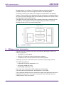
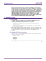
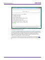
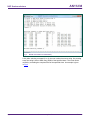
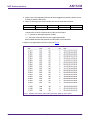
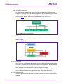
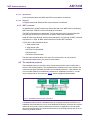
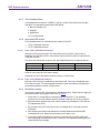
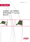
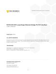
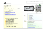
1
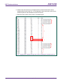
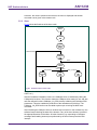
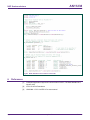
AN11238
LPC11Cxx CANopen network demo
Rev. 1 — 12 July 2012
Application note
Document information
Info
Content
Keywords
LPC11C12FBD48; LPC11C14FBD48; LPC11C22FBD48;
LPC11C24FBD48, LPC11Cxx, CAN, CANopen, on-chip, driver
Abstract
This application note illustrates how to use LPC11Cxx to setup a
simple CANopen network using the on-chip CAN/CANopen
drivers.
AN11238
NXP Semiconductors
LPC11Cxx CANopen network demo
Revision history
Rev
Date
Description
1
20120712
Initial release.
Contact information
For additional information, please visit: http://www.nxp.com
For sales office addresses, please send an email to: [email protected]
AN11238
Application note
All information provided in this document is subject to legal disclaimers.
Rev. 1 — 12 July 2012
© NXP B.V. 2012. All rights reserved.
2 of 34
AN11238
NXP Semiconductors
LPC11Cxx CANopen network demo
1. Introduction
This application note demonstrates the CAN peripheral and the on-chip CAN/CANopen
drivers of the LPC11Cxx.
1.1 CAN
The Controller Area Network (CAN) is a serial, asynchronous, multi-master
communication protocol for connecting electronic control modules, sensors and actuators
in automotive and industrial applications. Important features of CAN are:
• Very good signal integrity due to differential signaling.
• Collision and error detection and re-transmission possibilities.
• Multiple masters can exist within one network, allowing intelligent and redundant
systems.
A CAN frame exists of 11 identifier bits and 8 data bytes. CAN does not specify the
meaning of these identifier bits, nor the meaning of the data bytes. A high-level protocol
is necessary for this.
1.2 CANopen
CANopen is a type of high-level protocol for CAN bus, suitable for embedded networks. It
is built on top of CAL, using a subset of CAL services and communication protocols. It
provides an implementation of a distributed control system using the services and
protocols of CAL.
The central concept in CANopen is the device Object Dictionary (OD). For every node in
the network there exists an OD. The OD contains all parameters describing the device
and its network behavior. The OD is an ordered grouping of objects; each object is
addressed using a 16-bit index. To allow individual elements of structures of data to be
accessed, an 8-bit sub-index has been defined as well. Fig 1 shows the general layout of
CANopen OD.
Fig 1.
AN11238
Application note
General CANopen Object Dictionary structure
All information provided in this document is subject to legal disclaimers.
Rev. 1 — 12 July 2012
© NXP B.V. 2012. All rights reserved.
3 of 34
AN11238
NXP Semiconductors
LPC11Cxx CANopen network demo
The CANopen communication model defines four types of communication objects (COB):
• Administrative message.
• Service Data Object (SDO).
• Process Data Object (PDO).
• Predefined messages or Special Function Objects.
An SDO provides the access to entries of a device OD. PDO is used to transfer real-time
data. Predefined messages or special function objects include synchronization, time
stamp, emergency, node/life guarding and boot-up.
The relation between CAN communication, the Object Dictionary and application
software on a CANopen device is schematically illustrated in Fig 2.
Fig 2.
Schematic relationship between CAN-bus communication, Object Dictionary and
application software on a CANopen device
Different CAN identifiers support different communication objects, called COB-ID. The
predefined connection set defines PDO, SDO, emergency object and node error-control
identifier. It also supports the broadcasting of NMT module control, SYNC and time
stamp objects. Fig 3 shows the CAN-identifier allocation scheme.
AN11238
Application note
All information provided in this document is subject to legal disclaimers.
Rev. 1 — 12 July 2012
© NXP B.V. 2012. All rights reserved.
4 of 34
AN11238
NXP Semiconductors
LPC11Cxx CANopen network demo
Fig 3.
CANopen predefined CAN-identifiers
For CANopen protocol details, please refer to “CANopen Application Layer and
Communication Profile” (CiA DS301).
1.3 LPC11Cxx
Built around the Cortex-M0 architecture, LPC11Cxx is integrated with one C_CAN
controller, offering a low-cost entry point for CAN-based applications and on-chip
CAN/CANopen drivers.
The LPC11Cxx has one C_CAN controller. The C_CAN controller is designed to provide
a full implementation of the CAN protocol according to the CAN Specification Version
2.0B.
The main features of the LPC11Cxx CAN peripheral:
• Conforms to protocol version 2.0 parts A and B.
• Supports bit rate of up to 1 Mbit/s.
• Supports 32 Message Objects.
• Each Message Object has its own identifier mask.
• Provides programmable FIFO mode (concatenation of Message Objects).
• Provides maskable interrupts.
• Supports Disabled Automatic Retransmission (DAR) mode for time-triggered CAN
applications.
• Provides programmable loop-back mode for self-test operation.
• On-chip CAN/CANopen drivers.
The CAN controller consists of a CAN core, message RAM, a message handler, control
registers, and the APB interface. For communication on a CAN network, individual
AN11238
Application note
All information provided in this document is subject to legal disclaimers.
Rev. 1 — 12 July 2012
© NXP B.V. 2012. All rights reserved.
5 of 34
AN11238
NXP Semiconductors
LPC11Cxx CANopen network demo
Message Objects are configured. The Message Objects and Identifier Masks for
acceptance filtering of received messages are stored in the Message RAM.
All functions concerning the handling of messages are implemented in the Message
Handler. Those functions are the acceptance filtering, the transfer of messages between
the CAN Core and the Message RAM, and the handling of transmission requests as well
as the generation of the module interrupt.
The register set of the CAN controller can be accessed directly by an external CPU via
the APB bus. These registers are used to control/configure the CAN Core and the
Message Handler and to access the Message RAM.
Fig 4.
C_CAN block diagram
2. CANopen demo introduction
The demo requires a minimum of two LPC11Cxx boards. Three types of LPC11Cxx
boards are supported:
• Keil MCB11C14 (full support).
• IAR LPC11C14-SK (not all demo functions are supported).
• LPCXpresso LPC11C24 (not all demo functions are supported).
Additionally, a third LPC11Cxx board can be connected to create a larger network.
Three IDE’s are supported:
• Code Red LPCXpresso, tested with V4.1.5.
• Keil µVision, tested with V4.23.
• IAR EWARM, tested with V6.30.
The master node requires about 22 kB of flash and 1.5 kB of RAM.
The slave node only requires about 5 kB of flash and 1.5 kB of RAM.
The big difference between the two is because the master node application uses the full
printf() and scanf() functions. The master node and the slave node share the same
CANopen library, which is quite small.
AN11238
Application note
All information provided in this document is subject to legal disclaimers.
Rev. 1 — 12 July 2012
© NXP B.V. 2012. All rights reserved.
6 of 34
AN11238
NXP Semiconductors
LPC11Cxx CANopen network demo
For a fully functional demo, the following setup is required (Fig 5):
• One MCB11C14 board flashed with the master software.
• Two MCB11C14 boards flashed with slave software (both boards should have
unique CAN_NODE_ID).
• Master board must be connected to a computer’s serial port, running a terminal
program (e.g. PuTTY).
• To see what data is transmitted over the CAN bus, a CAN bus analyzer is highly
recommended.
CAN bus
CAN bus
analyzer
Slave node 2
Slave node 1
Serial connection
of master node
Fig 5.
Demo setup with three Keil MCB11C14 boards. The USB cables are only used for
supplying power to the boards
Not all features of CANopen are implemented in the demo, but the most-used features of
CANopen are supported:
• SDO expedited transfer: client & server.
• SDO segmented transfer: client & server.
• NMT: master, slave & boot-up.
• Heartbeat: producer & consumer.
The demo will demonstrate these features with the aid of a terminal program and the
onboard LEDs and buttons.
PDO transfer, synchronization, time stamp and emergency are not realized in the demo.
AN11238
Application note
All information provided in this document is subject to legal disclaimers.
Rev. 1 — 12 July 2012
© NXP B.V. 2012. All rights reserved.
7 of 34
AN11238
NXP Semiconductors
LPC11Cxx CANopen network demo
The LPC11Cxx also provides on-chip C_CAN drivers. In addition to the CAN ISP, the
boot ROM provides a CAN and CANopen API to simplify CAN application development.
It covers initialization, configuration, basic CAN send/receive as well as a CANopen SDO
interface. Callback functions are available to process received events. This application
makes use of these on-chip CAN/CANopen drivers, thereby reducing development time
and saving FLASH memory. However, the on-chip CANopen driver does not fully
implement all CANopen functions which are used by this demo, so for the demo
application an additional driver has been created. This driver is generic for all CANopen
functions, and thus is shared among the master and slave software.
3. Running the demo
3.1 Introduction
As stated in chapter 2, three types of LPC11Cxx boards are supported. The demo
consists of several small programs which can be run in two ways:
• Some functions of the demo rely on the onboard LEDs and buttons of the Keil
MCB11Cxx board.
• Some functions of the demo rely on the serial connection of the master node (to a
terminal program like PuTTY).
Note: Though multiple boards are supported, the MCB11Cxx is the only board on which
the demo can be partially run without serial connection. When using a board other than
the MCB11Cxx, there is no way of controlling the demo other than by the serial
connection.
3.2 Using the RS232 serial connection
The demo board can be controlled by a RS232 serial connecting by starting a terminal
application with the following settings:
• Baudrate: 115200.
• Databits: 8.
• Parity: none.
• Stopbits: 1.
After booting up, the master node prints a menu to the terminal, which can be seen in Fig
6.
AN11238
Application note
All information provided in this document is subject to legal disclaimers.
Rev. 1 — 12 July 2012
© NXP B.V. 2012. All rights reserved.
8 of 34
AN11238
NXP Semiconductors
LPC11Cxx CANopen network demo
Fig 6.
On startup of the CANopen master node, a menu is printed to the terminal
By entering any of the command numbers (1-11), an action is performed. Short summary
of these actions are as given below:
1 & 2) Sets the heartbeat producer time of the specified slave to 4000 ms, its heartbeat
consumer time to 4500 ms and the heartbeat consumer node ID to the master’s node ID.
This configures the slave to generate a heartbeat every 4000 ms and to track the
heartbeat of the master node. If the master does not send a heartbeat within every
4500 ms, the slave node tries to reset the master node.
3 & 4) Read the full SDO of the specified slave node and prints it to the terminal. Fig 7
shows the text from the terminal when reading the SDO of slave node 1 after configuring
it.
AN11238
Application note
All information provided in this document is subject to legal disclaimers.
Rev. 1 — 12 July 2012
© NXP B.V. 2012. All rights reserved.
9 of 34
AN11238
NXP Semiconductors
LPC11Cxx CANopen network demo
Fig 7.
Result of execution of command 3)
5 & 6) After selecting command (5 or 6), the user is asked to enter a string. On pressing
enter, the string is sent to SDO entry 2200H of the specified slave. The result can be
verified by re-reading the complete SDO of the specified slave. An example is given
in Fig 8.
AN11238
Application note
All information provided in this document is subject to legal disclaimers.
Rev. 1 — 12 July 2012
© NXP B.V. 2012. All rights reserved.
10 of 34
AN11238
NXP Semiconductors
LPC11Cxx CANopen network demo
Fig 8.
Result of execution of command 3) after previously changing SDO entry 2200H
by command 5)
7 & 8) By writing to SDO entry 2000H of the slave nodes, their LEDs (GPIO2) can be
controlled. After selecting command 7 or 8, the user is asked to enter a hexadecimal
value. After entering the same and pressing enter, the hexadecimal value is sent to the
SDO entry 2000H of the specified slave node. The slave node copies the value of SDO
entry 2000H to the LEDs (GPIO2) every 1 ms. Reading the SDO of the specified slave
shows the written hexadecimal value in SDO entry 2000H.
9 & 10) Reads SDO entry 2000H of specified slave and copies this value to the LEDs
(GPIO2) of the master node.
11) On start-up of the master node, it immediately starts sending its heartbeat every
4000 ms. By executing command 11), the master node stops sending its heartbeat,
thereby simulating a failing master node.
If one or more slave nodes have been configured by command 1) and 2), the configured
slave node(s) will send the NMT command “Reset Communication” after detection of the
missing heartbeat. Fig 9 shows the output of the terminal after the NMT command has
been received.
AN11238
Application note
All information provided in this document is subject to legal disclaimers.
Rev. 1 — 12 July 2012
© NXP B.V. 2012. All rights reserved.
11 of 34
AN11238
NXP Semiconductors
LPC11Cxx CANopen network demo
Fig 9.
Result of execution of command 11). Master received NMT command “Reset
Communication” from both slaves.
3.3 Using the onboard buttons
The demo can also be partially controlled by the onboard buttons. Please see Table 1 for
details of the functions that can be executed by the buttons.
Table 1.
Button
The demo can also be controlled by the onboard buttons. This table shows how
the functions are mapped to the buttons
Master board function
Slave board function
ISP
Simulate heartbeat failure of the master
node.
Simulate heartbeat failure of
the slave node.
PIO1_4
Read SDO entry 2000H (LED value) of slave Decrease SDO entry 2000H
node 1 and write this value to the LEDs of
(LED value) by 1.
the master node.
PIO1_5
Read SDO entry 2000H (LED value) of slave Increase SDO entry 2000H
node 2 and write this value to the LEDs of
(LED value) by 1.
the master node.
Note: If no CAN bus analyzer is connected and the master node is not connected to a
terminal, the effect of the heartbeat failure is hard to see.
In case of a heartbeat failure of a slave node, the effect of resetting the communication
can be seen as the LEDs reset to their default value (0x00, all LEDs off).
In case of a heartbeat failure of the master node, the effect cannot be seen without a
CAN bus analyzer or serial connection.
AN11238
Application note
All information provided in this document is subject to legal disclaimers.
Rev. 1 — 12 July 2012
© NXP B.V. 2012. All rights reserved.
12 of 34
AN11238
NXP Semiconductors
LPC11Cxx CANopen network demo
4. CANopen in more detail
Chapter 1.2 describes some basics of CANopen, this chapter will explore it in detail.
Central concept in CANopen is the Object Dictionary (OD), which will be explained first.
Several protocols are supported; the type of protocol used in the frame can be
determined by looking at the COB-ID (Chapter 1.2). The OD can be accessed by the
SDO protocol, which is described next. Finally more info regarding the NMT protocol and
the heartbeat protocol are given.
These functions are explained with the aid of screenshots of the CAN bus analyzer while
sniffing the traffic generated by the CANopen demo.
4.1 Object dictionary
As explained in chapter 1.2, the OD contains all parameters describing the device and its
network behavior. The OD can be seen as a big register, containing a number of items
which can be referenced to by a 16 bit index and an 8 bit sub index.
The OD has a defined structure, as can be seen in Table 2.
Table 2.
General CANopen Object Dictionary structure
CANopen object dictionary
Index
Object
0000
not used
0001 – 001F
Static Data Types (standard data types, e.g., Boolean, Integer16)
0020 – 003F
Complex Data Types (predefined structures composed of
standard data types, e.g., PDOCommPar. SDOParameter)
0040 – 005F
Manufacturer Specific Complex Data Types
0060 – 007F
Device Profile Specific Static Data Types
0080 – 009F
Device Profile Specific Complex Data Types
00A0 – 0FFF
reserved
1000 – 1FFF
Communication Profile Area (e.g., Device Type, Error Register,
Number of PDOs supported)
2000 – 5FFF
Manufacturer Specific Profile Area
6000 – 9FFF
Standardized Device Profile Area (e.g. “DSP-401 Device Profile
for I/O Modules” [3]: Read State 8 Input Lines, etc.)
A000 – FFFF
reserved
Entries in the OD can be marked as RO (ReadOnly), WO (WriteOnly) and RW
(Read/Write).
AN11238
Application note
All information provided in this document is subject to legal disclaimers.
Rev. 1 — 12 July 2012
© NXP B.V. 2012. All rights reserved.
13 of 34
AN11238
NXP Semiconductors
LPC11Cxx CANopen network demo
4.2 The COB-ID
As explained in chapter 1.1, a CAN frame consists of 11 identifier bits and 8 data bytes.
In CANopen, the 11 identifier bits are known as the CAN Object Identifiers (COB-ID). The
COB-ID specifies the CANopen protocol used for the current CAN frame. Table 3 shows
the predefined COB-IDs.
Table 3.
COB-ID
AN11238
Application note
CANopen predefined CAN object identifiers
Object
Mandatory/optional
0x000
NMT
Mandatory
0x080
SYNC
Optional
0x081 – 0x0FF
EMERGENCY
Optional
0x100
TIME STAMP
Optional
0x181 – 0x1FF
PDO1 (transmit)
Optional
0x201 – 0x27F
PDO1 (receive)
Optional
0x281 – 0x2FF
PDO2 (transmit)
Optional
0x301 – 0x37F
PDO2 (receive)
Optional
0x381 – 0x3FF
PDO3 (transmit)
Optional
0x401 – 0x47F
PDO3 (receive)
Optional
0x481 – 0x4FF
PDO4 (transmit)
Optional
0x501 – 0x57F
PDO4 (receive)
Optional
0x581 – 0x5FF
SDO (transmit / server)
Mandatory
0x601 – 0x67F
SDO (receive / client)
Mandatory
0x701 – 0x77F
NMT Error Control
Mandatory
All information provided in this document is subject to legal disclaimers.
Rev. 1 — 12 July 2012
© NXP B.V. 2012. All rights reserved.
14 of 34
AN11238
NXP Semiconductors
LPC11Cxx CANopen network demo
4.3 The SDO protocol
The SDO protocol is used for storing data in- and retrieving data from the OD. Any node
in the network may ask another node to read or store data by SDO. The initiator is
referred to as “client” and the node to which the request has been sent to, is referred to
as “server”. Fig 10 shows a graphical representation.
Fig 10. Object Dictionary definition of slave node
As it can be seen in Table 3, COB-IDs 0x601-0x67F are used by the client to
communicate with the server and COB-IDs 0x581-0x5FF are used by the server to
communicate with the client. The required COB-ID can be calculated as follows:
Client: COB-ID = 0x600 + [Node ID of server to reach] (broadcast not allowed)
Server: COB-ID = 0x580 + [Node ID of client to reach] (broadcast not allowed)
Two types of SDO access exist:
• Expedited SDO. This type of access is used to access any OD entry with size ≤ 4
bytes.
• Segmented SDO. This type of access is used to access any OD entry with size > 4
bytes, with theoretically up to an infinite number of bytes.
The SDO protocol specifies five commands:
• SDO segment download.
• Initiating download.
• Initiating upload.
• SDO segment upload.
• Abort SDO transfer.
AN11238
Application note
All information provided in this document is subject to legal disclaimers.
Rev. 1 — 12 July 2012
© NXP B.V. 2012. All rights reserved.
15 of 34
AN11238
NXP Semiconductors
LPC11Cxx CANopen network demo
With these five commands data can be read from- and written to the OD of an SDO
server. Two types of data structures are used for these five commands:
Format 1: Used for expedited transfer, or for initiating a segmented transfer
3 bits
cs
cs:
1 bit
reserved(=0)
2 bits
n
1 bit
e
1 bit
s
2 bytes
index
1 byte
subindex
4 bytes
data
Command Specifier. Indicates which command is used:
0: SDO segment download.
1: Initiating download.
2: Initiating upload.
3: SDO segment upload.
4: SDO abort transfer.
n:
Indicates the number of data bytes which do not contain data, only if both e
and s are set.
e:
If set, indicates an expedited transfer (data is encapsulated in the 4 data
bytes of the CAN frame). If cleared, transfer is of segmented type.
s:
If set, data size is indicated in n (e is set) or data size is indicated in data (e is
cleared).
index:
index of OD entry.
subindex: sub index of OD entry
data:
if e is set, data contains the data to transfer. If e is cleared and s is set,
indicates the data size of the segmented transfer.
Format 2: Used for transferring segments of data while a segmented transfer is in
progress
3 bits
cs
cs:
1 bit
t
3 bits
n
1 bit
l
7 bytes
data
Command Specifier. Indicates which command is used:
0: SDO segment download.
1: Initiating download.
2: Initiating upload.
3: SDO segment upload.
4: SDO abort transfer.
AN11238
Application note
t:
Toggle. This bit should toggle on every frame of the segmented transfer.
n:
Indicates the number of data bytes which do not contain data.
I:
Last frame. Indicates for segmented transfer that this is the last frame.
data:
Data bytes of segmented transfer.
All information provided in this document is subject to legal disclaimers.
Rev. 1 — 12 July 2012
© NXP B.V. 2012. All rights reserved.
16 of 34
AN11238
NXP Semiconductors
LPC11Cxx CANopen network demo
4.3.1 Expedited read
To perform an expedited read of OD entry 2000h, sub index 0x00, the client issues an
“initiate upload” command:
3 bits
1 bit
2 bits
1 bit
1 bit
cs = 2
reserved(=0)
n=0
e=0
s=0
2 bytes
Index =
0x2000
1 byte
Subindex
= 0x00
4 bytes
Data =
0x00
cs = 2 indicates an upload request.
n = 0, as s = 0.
e = 0, not used as no data is transferred, only a request.
s = 0, no size indicated (size is not mandatory for reading).
Index = 0x2000, transfer of index 2000h.
Subindex = 0x00, transfer of sub index 0x00.
Data = 0x00, should be zero when reading.
The server should respond with the following reply, assuming the entry exists and has 1
data byte containing 0xAA:
3 bits
1 bit
2 bits
1 bit
1 bit
cs = 2
reserved(=0)
n=3
e=1
s=1
2 bytes
Index =
0x2000
1 byte
Subindex
= 0x00
4 bytes
Data =
0xAA
cs = 2 indicates an upload.
n = 3, as only 1 data bytes is present and thus 3 data bytes are unused.
e = 1, indicating expedited transfer.
s = 1, size is indicated in n.
Index = 0x2000, transfer of index 2000h.
Subindex = 0x00, transfer of sub index 0x00.
Data = 0xAA, value of OD entry 0x2000, sub index 0x00 is 0xAA.
A capture of an expedited read can be found in Fig 11.
Fig 11. Capture from master node reading entry 2000h of slave node 1
AN11238
Application note
All information provided in this document is subject to legal disclaimers.
Rev. 1 — 12 July 2012
© NXP B.V. 2012. All rights reserved.
17 of 34
AN11238
NXP Semiconductors
LPC11Cxx CANopen network demo
4.3.2 Expedited write
To perform an expedited write of OD entry 2000h, sub index 0x00 with a single data byte
0x55, the client issues an “initiate download” command:
3 bits
1 bit
2 bits
1 bit
1 bit
cs = 1
reserved(=0)
n=3
e=1
s=1
2 bytes
Index =
0x2000
1 byte
Subindex
= 0x00
4 bytes
Data =
0x55
cs = 1 indicates an “initiating download” command.
n = 3, as only 1 data bytes is written and thus 3 data bytes are unused.
e = 1, indicating an expedited transfer.
s = 1, size is indicated in n.
Index = 0x2000, transfer of index 2000h.
Subindex = 0x00, transfer of sub index 0x00.
Data = 0x55, byte to be written.
The server should respond with the following reply, assuming the entry exists:
3 bits
1 bit
2 bits
1 bit
1 bit
cs = 3
reserved(=0)
n=0
e=0
s=0
2 bytes
Index =
0x2000
1 byte
Subindex
= 0x00
4 bytes
Data =
0x00
cs = 3 indicates an confirmation of the download.
n = 0, as s is 0.
e = 0, as no data is transferred.
s = 0, size is not indicated, as no data is transferred.
Index = 0x2000, transfer of index 2000h.
Subindex = 0x00, transfer of sub index 0x00.
Data = 0x00, as no data is transferred.
A capture of an expedited write can be found in Fig 12.
Fig 12. Capture from master node writing single data byte “0x55” to OD entry 2000h of
slave node 1
AN11238
Application note
All information provided in this document is subject to legal disclaimers.
Rev. 1 — 12 July 2012
© NXP B.V. 2012. All rights reserved.
18 of 34
AN11238
NXP Semiconductors
LPC11Cxx CANopen network demo
4.3.3 Segmented read
1. To perform a segmented read of OD entry 2200h, sub index 0x00, the client first
issues an “initiate upload” command:
3 bits 1 bit
2 bits
1 bit
1 bit
2 bytes 1 byte
4 bytes
Index =
Subindex Data =
cs = 2 reserved(=0) n = 0
e=0
s=0
0x2200
= 0x00
0x00
cs = 2 indicates an upload request.
n = 0, as s = 0.
e = 0, not used as no data is transferred, only a request.
s = 0, no size indicated (size is not mandatory for reading).
Index = 0x2200, wants to read from index 2200h.
Subindex = 0x00, wants to read from sub index 0x00.
Data = 0x00, should be zero when reading.
2. The server should respond with the following reply, assuming the entry exists:
3 bits 1 bit
2 bits
1 bit
1 bit
2 bytes 1 byte
4 bytes
Index =
Subindex Data =
cs = 2 reserved(=0) n = 0
e=0
s=0
0x2200
= 0x00
0x00
cs = 2 indicates an upload.
n = 0, as s is 0.
e = 0, indicating a segmented transfer.
s = 0, size is not indicated.
Index = 0x2200, transfer of index 2200h.
Subindex = 0x00, transfer of sub index 0x00.
Data = 0x00, as no data in transferred in this frame.
3. The client needs to send an acknowledge to the server:
3 bits
1 bit
3 bits
1 bit
cs = 3
t=0
n=0
l=0
7 bytes
data = 0x00
cs = 3, indicating an acknowledge.
t = 0, toggle bit starts at 0.
n = 0, not used with acknowledge.
l = 0, not used with acknowledge.
data = 0x00, not used with acknowledge.
4. The server responds with the first set of data:
3 bits
1 bit
3 bits
cs = 0
t=0
n=0
1 bit
l=0
7 bytes
data = ??
cs = 0, indicating SDO segment download.
t = 0, toggle bit starts at 0.
n = 0, all 7 data bytes contain data.
l = 0, this frame is not the last frame for the segmented transfer.
data is loaded with the data present at index 2200h, sub index 0x00.
AN11238
Application note
All information provided in this document is subject to legal disclaimers.
Rev. 1 — 12 July 2012
© NXP B.V. 2012. All rights reserved.
19 of 34
AN11238
NXP Semiconductors
LPC11Cxx CANopen network demo
5. Steps 3 and 4 are repeated (with the t bit been toggled every frame) until the server
is ready to send the last frame.
6. When ≤7 data bytes are left for transfer, the server sends the last frame:
3 bits
cs = 0
1 bit
t = ??
3 bits
n = ??
1 bit
l=1
7 bytes
data = ??
cs = 0, indicating SDO segment download.
t needs to be set to the inversed value of the previous frame.
n = 7 - [number of data bytes present in data].
l = 1, this frame is the last frame for the segmented transfer.
data is loaded with the data present at index 2200h, sub index 0x00.
A capture of a segmented read can be found in Fig 13.
Fig 13. Capture from master node reading OD entry 2200h of slave node 1
AN11238
Application note
All information provided in this document is subject to legal disclaimers.
Rev. 1 — 12 July 2012
© NXP B.V. 2012. All rights reserved.
20 of 34
AN11238
NXP Semiconductors
LPC11Cxx CANopen network demo
4.3.4 Segmented write
1. To perform a segmented write of OD entry 2200h, sub index 0x00, the client first
issues an “initiate download” command:
3 bits 1 bit
2 bits
1 bit
1 bit
2 bytes 1 byte
4 bytes
Index =
Subindex Data =
cs = 1 reserved(=0) n = 0
e=0
s=1
0x2200
= 0x00
length
cs = 1 indicates an download request.
n = 0, as e = 0.
e = 0, not used as no data is transferred, only a request.
s = 1, size indicated in data (not mandatory to indicate length).
Index = 0x2200, wants to write to index 2200h.
Subindex = 0x00, wants to write to sub index 0x00.
data = number of bytes to write (not mandatory to indicate length).
2. The server should respond with the following reply, assuming the entry exists:
3 bits 1 bit
2 bits
1 bit
1 bit
2 bytes 1 byte
4 bytes
Index =
Subindex Data =
cs = 3 reserved(=0) n = 0
e=0
s=0
0x2200
= 0x00
0x00
cs = 3 indicates an acknowledge.
n = 0, as s is 0.
e = 0, indicating a segmented transfer.
s = 0, size is not indicated.
Index = 0x2200, transfer of index 2200h.
Subindex = 0x00, transfer of sub index 0x00.
Data = 0x00, as no data in transferred in this frame.
3. The client may now send the data to be written:
3 bits
1 bit
3 bits
cs = 0
t=0
n=0
1 bit
l=0
7 bytes
data = ??
cs = 0, indicating SDO segment download.
t = 0, toggle bit starts at 0.
n = 0, all 7 data bytes contain data.
l = 0, this frame is not the last frame for the segmented transfer.
data is loaded with the data to be written.
AN11238
Application note
All information provided in this document is subject to legal disclaimers.
Rev. 1 — 12 July 2012
© NXP B.V. 2012. All rights reserved.
21 of 34
AN11238
NXP Semiconductors
LPC11Cxx CANopen network demo
4. The server should respond with an acknowledge:
3 bits
1 bit
3 bits
1 bit
cs = 1
t=0
n=0
l=0
7 bytes
data = ??
cs = 1, indicating an acknowledge.
t = 0, toggle bit starts at 0.
n = 0, not used for acknowledge.
l = 0, this not used for acknowledge.
data is don’t care when for acknowledge.
5. Steps 3 and 4 are repeated (with the t bit been toggled every frame) until the client is
ready to send the last frame.
6. When ≤7 data bytes are left for transfer, the client sends the last frame:
3 bits
1 bit
3 bits
1 bit
7 bytes
cs = 0
t = ??
n = ??
l=1
data = ??
cs = 0, indicating SDO segment download.
t needs to be set to the inversed value of the previous frame.
n = 7 - [number of data bytes present in data].
l = 1, this frame is the last frame for the segmented transfer.
data is loaded with the data to be written.
A capture of a segmented write can be found in Fig 14.
Fig 14. Capture from master node writing to OD entry 2200h of slave node 1
AN11238
Application note
All information provided in this document is subject to legal disclaimers.
Rev. 1 — 12 July 2012
© NXP B.V. 2012. All rights reserved.
22 of 34
AN11238
NXP Semiconductors
LPC11Cxx CANopen network demo
4.4 The NMT protocol
The NMT (Network Management) protocol is used for changing the NMT state of the
CANopen nodes. Any node in the network may send a NMT command to another node,
or all nodes by broadcasting, in the network. The node which sends the NMT command
is referred to as “Master”, while the node(s) addressed is/are referred to as
“Slave(s)”. Fig 15 shows a graphical representation.
Fig 15. NMT master / slave structure
4.4.1 NMT states
Each NMT slave has a state machine, consisting of four states. These four states are
shown in Fig 16.
Fig 16. NMT state machine of an NMT slave
4.4.1.1 Initializing
After Power-On all NMT slaves change their state to Initializing. After internal initialization
of the NMT slave, the NMT slave changes its state to Pre-Operational. Besides this state
change, the NMT protocol is the only way to change the present state of an NMT slave.
When changing to Pre-Operational it should send a bootup message.
The bootup message is a frame with COB-ID 0x700 + [node-id of NMT slave]. There is
just one data byte encapsulated in the bootup frame, with a fixed value of 0x00.
4.4.1.2 PreOperational
In the pre-operational state SDO communication is allowed, while PDO communication is
inhibited.
AN11238
Application note
All information provided in this document is subject to legal disclaimers.
Rev. 1 — 12 July 2012
© NXP B.V. 2012. All rights reserved.
23 of 34
AN11238
NXP Semiconductors
LPC11Cxx CANopen network demo
4.4.1.3 Operational
In the operational state both SDO and PDO communication are allowed.
4.4.1.4 Stopped
In stopped mode both SDO and PDO communication are inhibited.
4.4.2 NMT command
As stated before, an NMT master may change the state of an NMT slave by sending an
NMT command. COB-ID is used for sending the command.
The NMT command has two data bytes. The first data byte is the Command Specifier
(CS) and the second byte is the node-ID to specify which node is addressed.
Node-ID 0x00 is also allowed, which is the broadcast ID. On receiving an NMT command
with Node-ID == 0x00, all NMT slaves should execute the NMT command.
CS can have a few predefined values:
1: Start remote node.
2: Stop remote node.
128: Enter Pre-Operational.
129: Reset node.
130: Reset Communication.
The two reset commands allow a full reset (129, reset node) or to only reset the
communication parameters (130, reset communication).
4.5 The heartbeat protocol
The heartbeat protocol is part of the error control protocol and is used to check that a
device is still working properly. The heartbeat protocol defines one or more nodes in the
network producing a heartbeat, referred to as “heartbeat producers”. It also defines one
or more nodes watching for heartbeats, referred to as “heartbeat consumers”. A node
may be both producer and consumer. Fig 17 shows a graphical representation.
Fig 17. Heartbeat producers and consumers
A heartbeat producer sends a heartbeat frame on a regular interval (0 to 65535 ms). A
heartbeat consumer listens to one or more heartbeats, and has a consumer time interval
defined for every node. If the consumer did not receive a heartbeat from a node within
this consumer time interval, it knows that that node is not working properly and will try to
reset it by the NMT protocol.
AN11238
Application note
All information provided in this document is subject to legal disclaimers.
Rev. 1 — 12 July 2012
© NXP B.V. 2012. All rights reserved.
24 of 34
AN11238
NXP Semiconductors
LPC11Cxx CANopen network demo
4.5.1 The heartbeat frame
A heartbeat frame consists of a COB-ID = 0x700 + [node-id of producer] and a single
data byte. The data byte represents the NMT status:
0: Boot-up (Chapter 4.4).
4: Stopped.
5: Operational.
127: Pre-Operational.
4.5.2 Associated OD entries
The heartbeat protocol is controlled by two indexes in the OD:
• 1016h. Heartbeat consumer.
• 1017h. Heartbeat producer.
4.5.2.1 Index 1016 h (Heartbeat Consumer)
OD entry 1016h is an array type. Sub index 0x00 is an entry with 1 byte in size, is
ReadOnly and should be set to a value which is the maximum number of nodes which it
is allowed to watch.
The other sub indexes are 4 bytes in size, are ReadWrite and are encoded as follows:
bits
31…24
32…16
15…0
Value
0
Node-ID
Heartbeat time
Encoding
-
Unsigned8
Unsigned16
Node-ID is the node-ID of the node to watch.
Heartbeat time is the heartbeat consumer interval, in milliseconds.
4.5.2.2 Index 1017h (Heartbeat Producer)
OD entry 1017h only has a valid entry at sub index 0x00. This entry is ReadWrite and
has a size of 2 bytes. The value specified in these 2 bytes (encoded as Unsigned16) is
the heartbeat producer interval in milliseconds.
4.5.3 Heartbeat example
The following example will demonstrate the heartbeat protocol. Please see the logging of
the CAN bus while running parts of the demo in Fig 18.
1. Slave node 1 is configured by executing terminal command 1). The heartbeat
producer time is set to 4000ms and the heartbeat consumer time is set to 4500ms.
2. Both the master node and the slave node are producing a heartbeat. Their status is
Pre-Operational (0x7F).
3. By pressing button ISP of the slave node, a heartbeat failure of the slave node is
simulated.
4. After 4500ms the master node detects the missing heartbeat and sends NMT
command 0x82 (130, Reset Communication) to the slave node.
5. In reaction to NMT command 130, the slave resets its communication parameter.
After completing the Initialization state, it enters the Pre-Operational state again and
sends the boot-up message.
AN11238
Application note
All information provided in this document is subject to legal disclaimers.
Rev. 1 — 12 July 2012
© NXP B.V. 2012. All rights reserved.
25 of 34
AN11238
NXP Semiconductors
LPC11Cxx CANopen network demo
6. Master node sees the boot-up message and has remembered that there was a
heartbeat failure at this node. So, it re-configures the slave node with a value for the
heartbeat producer and heartbeat consumer OD entries.
7. Both the master and the slave produce a heartbeat again.
1
2
3
4
5
6
7
Fig 18. Logging of the CAN bus during some actions regarding the heartbeat protocol.
AN11238
Application note
All information provided in this document is subject to legal disclaimers.
Rev. 1 — 12 July 2012
© NXP B.V. 2012. All rights reserved.
26 of 34
AN11238
NXP Semiconductors
LPC11Cxx CANopen network demo
5. Software
5.1 Software organization
Three IDE’s are supported:
• Code Red LPCXpresso
• Keil µVision
• IAR EWARM
The source code and project files are structured as in Table 4:
Table 4.
File structure used for the CANopen application
Directory/file
Description
Projects/LPCXpresso/Master.zip
Project file of master node for LPCXpresso
Projects/LPCXpresso/Slave.zip
Project file of slave node for LPCXpresso
Projects/Keil/Master/
Project directory of master node for Keil
Projects/Keil/Slave/
Project directory of slave node for Keil
Projects/IAR/Master/
Project directory of master node for IAR
Projects/IAR/Slave/
Project directory of slave node for IAR
Software/CMSIS
CMSIS source files
Software/Drivers/src/CANopen/canopen_driver.c
CANopen driver source
Software/Drivers/src/UART/uart.c
UART driver source
Software/Drivers/src/Retarget/
Source directory for retargeting printf() and
scanf()
Software/Drivers/inc/CANopen/canopen_driver.h
CANopen driver header
Software/Drivers/inc/CANopen/rom_drivers.h
On-chip drivers header
Software/Drivers/inc/CANopen/rom_driver_CAN.h
On-chip CAN driver header
Software/Drivers/inc/UART/uart.h
UART driver header
Software/Master/src/main.c
Application source for master node
Software/Master/src/CAN_Node_Def.c
Node definition source file for master node
Software/Master/inc/CAN_Node_Def.h
Node definition header for master node
Software/Slave/src/main.c
Application source for slave node
Software/Slave/src/CAN_Node_Def.c
Node definition source file for slave node
Software/Slave/inc/CAN_Node_Def.h
Node definition header for slave node
5.2 Application
For both the master and the slave node most of the work is done by the CANopen driver
(Chapter 5.3). The CANopen device definition (Chapter 5.4) also has an important role in
the software. This chapter explains on a higher level how the software behaves.
5.2.1 Master
Fig 19 shows the flowchart of the master node.
AN11238
Application note
All information provided in this document is subject to legal disclaimers.
Rev. 1 — 12 July 2012
© NXP B.V. 2012. All rights reserved.
27 of 34
AN11238
NXP Semiconductors
LPC11Cxx CANopen network demo
Reset
Initialize
HW
Done
Initialize
CANopen
driver
Done
Initialize
CANopen
SDO
Received NMT reset command
Done
Print
menu
Invalid CMD enterd
Done
Wait for
CMD
Done
Valid CMD entered
Execute
CMD
Done
Print
result
Fig 19. Flowchart of the master node
After reset, the hardware is initialized (e.g. the LPC11Cxx and its peripherals, LEDs,
UART, etc.).
After the hardware initialization is done, the CANopen driver is initialized by calling the
CANopenInit functions. This function makes the CANopen driver ready for use, and also
calls the callback functions CANopen_Init_SDO, thereby initializing the CANopen SDO
parameters. This also enables the production of the heartbeat every 4000 ms. The
CANopen_Init_SDO function can be called anytime upon receiving the NMT reset
command.
After the CANopen driver is fully initialized, the menu with available commands is printed.
Next, a loop is entered which waits for a command. This command can come from the
RS232 connection or from the buttons on the MCB11C14 board. Upon entering a valid
command it will be executed (e.g. read SDO of slave and print it to the terminal). After
AN11238
Application note
All information provided in this document is subject to legal disclaimers.
Rev. 1 — 12 July 2012
© NXP B.V. 2012. All rights reserved.
28 of 34
AN11238
NXP Semiconductors
LPC11Cxx CANopen network demo
execution, the result is printed to the terminal, the menu is displayed and another
command can be given to the master node.
5.2.2 Slave
Fig 20 shows the flowchart of the slave node.
Reset
Initialize
HW
Done
Initialize
CANopen
driver
Done
Received NMT reset command
Initialize
CANopen
SDO
Done
Done
Check
buttons
PIO1_4 pushed
PIO1_5 pushed
ISP pushed
Simulate
heartbeat
fail
Decrease
LED
value
Increase
LED
value
Fig 20. Flowchart of the slave node
After reset, the hardware is initialized (e.g. the LPC11Cxx and its peripherals, LEDs,
UART, etc.).
After the hardware initialization is done, the CANopen driver is initialized by calling the
CANopenInit functions. This function makes the CANopen driver ready for use, and also
calls the callback functions CANopen_Init_SDO, thereby initializing the CANopen SDO
parameters. This also enables the production of the heartbeat every 4000 ms. The
CANopen_Init_SDO function can be called anytime upon receiving the NMT reset
command.
After initializing the CANopen driver an endless loop is entered. In this endless loop, the
software keeps checking the state of the buttons. If any of the three buttons is pressed,
the appropriate action will be taken. All other functions (e.g. responding to CANopen
messages and handling timeouts) are performed by the timer interrupt and the CAN
interrupt.
AN11238
Application note
All information provided in this document is subject to legal disclaimers.
Rev. 1 — 12 July 2012
© NXP B.V. 2012. All rights reserved.
29 of 34
AN11238
NXP Semiconductors
LPC11Cxx CANopen network demo
5.3 CANopen driver
To use the CANopen driver, the file CANopen.h should be included in the project.
A number of functions are present in the API for reading or writing to other nodes. In
order for the CANopen driver to work, one should have the following prerequisites in its
applications:
• When the application is initializing, function CANopenInit must be called to initialize
the CANopen driver and the CAN peripheral.
• Functions CANopen_1ms_tick must be called every 1ms.
• CANopen_Init_SDO callback functions must be present in the application. This
functions is called when initializing the CANopen driver and on reset of the node (e.g.
by NMT command).
• CANopen_NMT_Reset_Node_Received callback functions must be present in the
application. This function is called on receiving the NMT command “Reset Node”.
• CANopen_NMT_Reset_Comm_Received callback functions must be present in the
application. This function is called on receiving the NMT command “Reset
Communication”.
• CANopen_Heartbeat_Consumer_Failed callback function must be present in the
application. This functions is called when one of the node listed in the WatchList
does not transmit its heartbeat on time.
• CANopen_NMT_Consumer_Bootup_Received callback functions must be present in
the applications.
Please refer to the application source code (“main.c”) of the master node and the
description in the “canopen_driver.c” file to see what functions are available and how
to use them.
More information on the on-chip CAN/CANopen drivers can be found in chapter 17 of
the LPC11Cxx User Manual.
5.4 CANopen device definition
The device definition defines what the OD looks like. Two files are required for a
complete definition:
• CAN_Node_Def.c
• CAN_Node_Def.h
These two files define multiply of things regarding the behavior of the CANopen node, in
particular:
• Its Node ID.
• Its Object Dictionary (OD).
• Variables coupled to the OD.
• SDO Client timeout value.
• Watchlist, used for initial guarding of nodes.
Fig 21 and Fig 22 show the node definition used for the slave node.
AN11238
Application note
All information provided in this document is subject to legal disclaimers.
Rev. 1 — 12 July 2012
© NXP B.V. 2012. All rights reserved.
30 of 34
AN11238
NXP Semiconductors
LPC11Cxx CANopen network demo
Fig 21. Node definition header file for slave node
AN11238
Application note
All information provided in this document is subject to legal disclaimers.
Rev. 1 — 12 July 2012
© NXP B.V. 2012. All rights reserved.
31 of 34
AN11238
NXP Semiconductors
LPC11Cxx CANopen network demo
Fig 22. Node definition source file for slave node
6. References
AN11238
Application note
[1]
CANopen Application Layer and Communication Profile”, CiA Draft Standard 301,
Version 4.02
[2]
LPC11C12/C14 Data sheet
[3]
UM10398 – LPC111x/LPC11Cxx user manual
All information provided in this document is subject to legal disclaimers.
Rev. 1 — 12 July 2012
© NXP B.V. 2012. All rights reserved.
32 of 34
AN11238
NXP Semiconductors
LPC11Cxx CANopen network demo
7. Legal information
7.1 Definitions
Draft — The document is a draft version only. The content is still under
internal review and subject to formal approval, which may result in
modifications or additions. NXP Semiconductors does not give any
representations or warranties as to the accuracy or completeness of
information included herein and shall have no liability for the consequences
of use of such information.
7.2 Disclaimers
Limited warranty and liability — Information in this document is believed to
be accurate and reliable. However, NXP Semiconductors does not give any
representations or warranties, expressed or implied, as to the accuracy or
completeness of such information and shall have no liability for the
consequences of use of such information. NXP Semiconductors takes no
responsibility for the content in this document if provided by an information
source outside of NXP Semiconductors.
In no event shall NXP Semiconductors be liable for any indirect, incidental,
punitive, special or consequential damages (including - without limitation lost profits, lost savings, business interruption, costs related to the removal
or replacement of any products or rework charges) whether or not such
damages are based on tort (including negligence), warranty, breach of
contract or any other legal theory.
Notwithstanding any damages that customer might incur for any reason
whatsoever, NXP Semiconductors’ aggregate and cumulative liability
towards customer for the products described herein shall be limited in
accordance with the Terms and conditions of commercial sale of NXP
Semiconductors.
Right to make changes — NXP Semiconductors reserves the right to make
changes to information published in this document, including without
limitation specifications and product descriptions, at any time and without
notice. This document supersedes and replaces all information supplied prior
to the publication hereof.
Suitability for use — NXP Semiconductors products are not designed,
authorized or warranted to be suitable for use in life support, life-critical or
safety-critical systems or equipment, nor in applications where failure or
malfunction of an NXP Semiconductors product can reasonably be expected
to result in personal injury, death or severe property or environmental
damage. NXP Semiconductors and its suppliers accept no liability for
inclusion and/or use of NXP Semiconductors products in such equipment or
applications and therefore such inclusion and/or use is at the customer’s
own risk.
Applications — Applications that are described herein for any of these
products are for illustrative purposes only. NXP Semiconductors makes no
representation or warranty that such applications will be suitable for the
specified use without further testing or modification.
Semiconductors accepts no liability for any assistance with applications or
customer product design. It is customer’s sole responsibility to determine
whether the NXP Semiconductors product is suitable and fit for the
customer’s applications and products planned, as well as for the planned
application and use of customer’s third party customer(s). Customers should
provide appropriate design and operating safeguards to minimize the risks
associated with their applications and products.
NXP Semiconductors does not accept any liability related to any default,
damage, costs or problem which is based on any weakness or default in the
customer’s applications or products, or the application or use by customer’s
third party customer(s). Customer is responsible for doing all necessary
testing for the customer’s applications and products using NXP
Semiconductors products in order to avoid a default of the applications and
the products or of the application or use by customer’s third party
customer(s). NXP does not accept any liability in this respect.
Export control — This document as well as the item(s) described herein
may be subject to export control regulations. Export might require a prior
authorization from competent authorities.
Evaluation products — This product is provided on an “as is” and “with all
faults” basis for evaluation purposes only. NXP Semiconductors, its affiliates
and their suppliers expressly disclaim all warranties, whether express,
implied or statutory, including but not limited to the implied warranties of noninfringement, merchantability and fitness for a particular purpose. The entire
risk as to the quality, or arising out of the use or performance, of this product
remains with customer.
In no event shall NXP Semiconductors, its affiliates or their suppliers be
liable to customer for any special, indirect, consequential, punitive or
incidental damages (including without limitation damages for loss of
business, business interruption, loss of use, loss of data or information, and
the like) arising out the use of or inability to use the product, whether or not
based on tort (including negligence), strict liability, breach of contract, breach
of warranty or any other theory, even if advised of the possibility of such
damages.
Notwithstanding any damages that customer might incur for any reason
whatsoever (including without limitation, all damages referenced above and
all direct or general damages), the entire liability of NXP Semiconductors, its
affiliates and their suppliers and customer’s exclusive remedy for all of the
foregoing shall be limited to actual damages incurred by customer based on
reasonable reliance up to the greater of the amount actually paid by
customer for the product or five dollars (US$5.00). The foregoing limitations,
exclusions and disclaimers shall apply to the maximum extent permitted by
applicable law, even if any remedy fails of its essential purpose.
7.3 Trademarks
Notice: All referenced brands, product names, service names and
trademarks are property of their respective owners.
Customers are responsible for the design and operation of their applications
and products using NXP Semiconductors products, and NXP
AN11238
Application note
All information provided in this document is subject to legal disclaimers.
Rev. 1 — 12 July 2012
© NXP B.V. 2012. All rights reserved.
33 of 34
AN11238
NXP Semiconductors
LPC11Cxx CANopen network demo
8. Contents
1.
1.1
1.2
1.3
2.
3.
3.1
3.2
3.3
4.
4.1
4.2
4.3
4.3.1
4.3.2
4.3.3
4.3.4
4.4
4.4.1
4.4.1.1
4.4.1.2
4.4.1.3
4.4.1.4
4.4.2
4.5
4.5.1
4.5.2
4.5.2.1
4.5.2.2
4.5.3
5.
5.1
5.2
5.2.1
5.2.2
5.3
5.4
6.
7.
7.1
7.2
7.3
8.
Introduction ......................................................... 3
CAN ................................................................... 3
CANopen............................................................ 3
LPC11Cxx .......................................................... 5
CANopen demo introduction.............................. 6
Running the demo ............................................... 8
Introduction ........................................................ 8
Using the RS232 serial connection .................... 8
Using the onboard buttons ............................... 12
CANopen in more detail .................................... 13
Object dictionary .............................................. 13
The COB-ID ..................................................... 14
The SDO protocol ............................................ 15
Expedited read ................................................. 17
Expedited write................................................. 18
Segmented read ............................................... 19
Segmented write .............................................. 21
The NMT protocol ............................................ 23
NMT states ....................................................... 23
Initializing ......................................................... 23
PreOperational ................................................. 23
Operational....................................................... 24
Stopped ............................................................ 24
NMT command................................................. 24
The heartbeat protocol ..................................... 24
The heartbeat frame ......................................... 25
Associated OD entries ..................................... 25
Index 1016 h (Heartbeat Consumer) ................ 25
Index 1017h (Heartbeat Producer) ................... 25
Heartbeat example ........................................... 25
Software ............................................................. 27
Software organization ...................................... 27
Application........................................................ 27
Master .............................................................. 27
Slave ................................................................ 29
CANopen driver................................................ 30
CANopen device definition ............................... 30
References ......................................................... 32
Legal information .............................................. 33
Definitions ........................................................ 33
Disclaimers....................................................... 33
Trademarks ...................................................... 33
Contents ............................................................. 34
Please be aware that important notices concerning this document and the product(s)
described herein, have been included in the section 'Legal information'.
© NXP B.V. 2012.
All rights reserved.
For more information, please visit: http://www.nxp.com
For sales office addresses, please send an email to: [email protected]
Date of release: 12 July 2012
Document identifier: AN11238