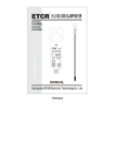
1
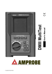
1.1 Introduction
EX9017H-M is a analog input module with 8 input channels.
Eight channels are differential type and individual channel configuration
support .
Specifications:
Interface: RS-485, 2 wires
Speed (bps): 1200, 2400, 4800, 9600, 19.2K, 38.4K , 115.2K
Analog Input type: Differential input
Support individual channel configuration
Analog Channels Numbers: 8
Analog Resolution: 16/12(fast mode) bits
Unit Conversion: mV, V or mA
Voltage range: +/-10V,+/-5V,+/-1V,+/-500mV,+/-150mV,+/-20mA
Sampling Rate :10/ 50(fast mode) Samples/Second
Bandwidth : 15.7 Hz
Accuracy : ±0.1%
Zero Drift : 0.5µV/°C
Span Drift : 25ppm/°C
CMR@50/60Hz : 150dB
NMR@50/60Hz : 100dB
Input Impedance : 20M Ohms
Current Measurement: ±20mA (with external 125 ohm resistor)
Power supply: +10V to +30V
1
1.2 Wire connection
2
1.2.1 Block Diagrams
Vin 7+
Vin 7-
EEPROM
Vin 6+
1.2.2 Wiring diagram for the EX-9017H-M
Single
Controller
ADC
Photo-Isolation
Vin 6-
MUX
Vin 1+
Vin 1-
Data+
Data+Vs
GND
RS485
Interface
Vin 0+
+5V
Vin 0-
Power
Supply
EX9017HM
1.3 Default Settings
Default settings for the EX-9017H-M modules are as follows:
. Module Address: 01
. Protocol: Modbus RTU
. Analog Input Type: type 08 (-10 ~ +10V)
. Baud Rate: 9600 bps
. Checksum disabled
. Engineering unit format
. Filter set at 60Hz rejection
3
1.4 INIT* Mode Operation
Each EX9000 module has a build-in EEPROM to store configuration
information such as address, type, baudrate and other information.
Sometimes, user may forget the configuration of the module. Therefore,
the EX9000 have a special mode named "INIT* mode" to help user to
resolve the problem. The "INIT* mode" is setting as Address=00,
Budrate=9600bps, no Checksum .
Originally, the INIT* mode is accessed by connecting the INIT* terminal
to the GND terminal. New EX9000 modules have the INIT* switch
located on the rear side of the module to allow easier access to the INIT*
mode. For these modules, INIT* mode is accessed by sliding the INIT*
switch to the Init position as shown below.
To enable INIT* mode, please following these steps:
Step1. Power off the module
Step2. Connect the INIT* pin with the GND pin.
(or sliding the INIT* switch to the Init* ON position)
Step3. Power on
Step4. Send command $002 (cr) in 9600bps to read the
Configuration stored in the module's EEPROM.
There are commands that require the module to be in INIT* mode. They
are:
1. %AANNTTCCFF when changing the Baud Rate and checksum
settings. See Section 2.1 for details.
2. $AAPN, See Section 2.14 for details.
4
1.5 Module Status for DIO, AIO
Power On Reset or Module Watchdog Reset will let all output
goto Power On Value. And the module may accept the host's command
to change the output value.
Host Watchdog Timeout will let all output goto Safe Value. The
module's status(read by command~AA0) will be 04, and the output
command will be ignored.
1.6 Dual Watchdog Operation for DIO, AIO
Dual Watchdog=Module Watchdog + Host Watchdog
The Module Watchdog is a hardware reset circuit to monitor the
module's operating status. While working in harsh or noisy environment,
the module may be down by the external signal. The circuit may let the
module to work continues and never halt.
The Host Watchdog is a software function to monitor the host's
operating status. Its purpose is to prevent the network from
communication problem or host halt. When the timeout interval expired,
the module will turn all outputs to predefined Safe Value. This can
prevent the controlled target from unexpected situation.
The EX9000 module with Dual Watchdog may let the control
system more reliable and stable.
1.7 Reset Status
The Reset Status is set while the module power on or reset by module
watchdog and is cleared while the command read Reset Status ($AA5)
applied. This is useful for user to check the module's working status.
When the Reset Status is set means the module is reset and the output
may be changed to the PowerOn Value. When the Reset Status is clear
means the module is not rested and the output is not changed.
5
1.8 Calibration(Warning: Please don't calibrate before you
really understand.)
Set the module of data format to which you wish to calibration first.
Protocol: ASCII mode.
Address: 01
Input type: which type you wish to calibration
Filter: which rejection you wish to calibration
Perform Zero Calibration:
1. Send the command “$01501” to CH0 enable, CH1~7 disable.
2. Apply zero voltage/current to module’s channel 0 (Vin0+ to Vin0-)
3. Send the command “~01E1” to enable calibration.
4. Send the command “$011” to perform zero calibration.
Perform Span Calibration:
1. Send the command “$01502” to CH1 enable, CH0 & 2~7 disable.
2. Apply Span voltage/current to module’s channel 1
Type code
Span
08
09
0A
0B
0C
0D
+10V +5V +1V +500mV +150mV +20mA
3. Send the command “~01E1” to enable calibration.
4. Send the command “~01CALS00550000” to perform span calibration.
5. Send the command “#011” to check the CH0 input value is correct.
If the value is over the signal, decrease the value “550000”.
If the value is less the signal, increase the value “550000”.
The value should between 500000~5B0000, Hexadecimal format.
Note: While calibrate type of current, need connect external shunt resistor,
125ohms, 0.1% to channel1.
6
1.9 Configuration Tables
Baud Rate Setting (CC)
Code
Baud rate
03
04
05
06
07
08
09
0A
1200
2400
4800
9600
19200
38400
57600
115200
Sensor Type & V/I Range Setting (TT)
Code Range
08
09
0A
0B
0C
0D
-10V ~ +10V
-5V ~ +5V
-1V ~ +1V
-500mV
+500mV
-150mV
+150mV
Format
+F.S.
Zero
-F.S.
Engineer unit
+10.000
+00.000
-10.000
% of F.S.R.
+100.00
+000.00
-100.00
2’s
complement
7FFF
0000
8000
Engineer unit
+50.000
+05.000
-05.000
% of F.S.R.
+100.00
+000.00
-100.00
2’s
complement
7FFF
0000
8000
Engineer unit
+1.0000
+000.00
-1.0000
% of F.S.R.
+100.00
+000.00
-100.00
2’s
complement
7FFF
0000
8000
Engineer unit
+500.00
+000.00
-500.00
+100.00
+000.00
-100.00
2’s
complement
7FFF
0000
8000
Engineer unit
+150.00
+0.0000
-150.00
+100.00
+000.00
-100.00
2’s
complement
7FFF
0000
8000
Engineer unit
+20.000
+0.0000
-20.000
% of F.S.R.
+100.00
+000.00
-100.00
2’s
complement
7FFF
0000
8000
~ % of F.S.R.
~ % of F.S.R.
-20mA ~ +20mA
7
Data Format Setting (FF)
7
6
FS
Key
DF
MS
CS
FS
5
CS
4
MS
3
2
reserved
Description
Data format
00: Engineering unit
01: % of FSR (full scale range)
10: 2’s complement hexadecimal
Mode setting
0: normal mode (16bit)
1: fast mode (12bit)
Checksum (CRC in Modbus) setting
0: Disabled
1: Enabled
Filter setting
0: 60Hz rejection
1: 50Hz rejection
Note: The reserved bits should be zero.
8
1
0
DF
2.0 Command set
2.1 %AANNTTCCFF
Description: Set Module Configuration.
Syntax: %AANNTTCCFF[CHK](cr)
%
a delimiter character
AA
address of setting/response module(00 to FF)
NN
TT
CC
FF
new address for setting/response module(00 to FF)
represents the type code. Type code determines the
input range.
If TT=FF the type of all channels keep no change.
new baudrate for setting module.
new data format for setting module.
IF the configuration with new baudrate or new checksum setting, before
using this command, the rear slide switch must be in the ON(INIT*)
position. The new setting is saved in the EEPROM and will be effective
after the next power-on reset.
Response: Valid Command:
Invalid Command:
!AA
?AA
Example:
Receive: !02
Command: %0203080602
Set module address 02 to 03.
Input type code=08 (-10~+10V) for all channels
Baudrate=06 (9600)
Dataformat=02 (2’s complement hexadecimal)
9
2.2 #AA
Description: Read Analog Input
Syntax: #AA[CHK](cr)
#
delimiter character
AA address of reading/response module(00 to FF)
Response: Valid Command:
>(Data)
(Data) analog input value for its format while use #AA command
to EX-9018BL/9019, the data is the combination for each
channel respectively.
Example :
Command: #04
Receive:>+051.23+041.53+072.34-023.56+100.00051.33+066.46+074.22
The module address 04 is EX-9018BL/9019. Read address 04 for
getting data of all 8 channels.
10
2.3 #AAN
Description : Read Analog Input from channel N
Syntax : #AAN[CHK](cr)
#
delimiter character
AA address of reading/response module(00 to FF)
N
channel to read, from 0 to 7
Response: Valid Command:
>(Data)
Invalid Command:
?AA
(Data) analog input value for its format
Example :
Command : #032
Receive : >+025.13
Read address 03 channel 2, get data successfully.
Command : #029
Receive : ?02
Read address 02 channel 9, return error channel number.
11
2.4 $AA0
Description: Perform Span Calibration
Syntax: $AA0[CHK](cr)
$
delimiter character
AA address of setting/response module (00 to FF)
0
command for performing zero calibration
Response: Valid Command:
!AA
Invalid Command:
?AA
Example :
Command : $010
Receive : !01
Perform address 01 zero calibration on channel 0, return success.
Command : $020
Receive : ?02
Perform address 02 zero calibration on channel 2 , return not
enable calibration before perform calibration command.
Warning: Please don't calibrate before you really understand.
12
2.5 $AA1
Description: Perform Zero Calibration
Syntax: $AA1[CHK](cr)
$
delimiter character
AA address of setting/response module (00 to FF)
1
command for performing span calibration
Response: Valid Command:
!AA
Invalid Command:
?AA
Example:
Command: $011
Receive: !01
Perform address 01 span calibration on channel 0, return success.
Command: $021
Receive: ?02
Perform address 02 span calibration on channel 2, return not
enable calibration before perform calibration command.
Warning: Please don't calibrate before you really understand.
13
2.6 $AA2
Description: Read configuration.
Syntax: $AA2[CHK](cr)
$
delimiter character
AA
address of reading/response module (00 to FF)
2
command for read configuration
Response: Valid Command:
Invalid Command:
TT
CC
FF
!AATTCCFF
?AA
type code of module
baudrate code of module
data format of module
Example:
Command: $012
Receive: !01400600
Read the configuration of module 01, input range of -2.5~+2.5V,
baudrate 9600, no checksum.
Note: check configuration Tables
14
2.7 $AA5VV
Description: Set Channel Enable
Syntax: $AA5VV[CHK](cr)
$
delimiter character
AA
address of setting/response module (00 to FF)
5
command for set channel enable
VV
are two hexadecimal values. The values are interpreted by
the module as two binary words (4-bit). The first word
represents the status of channel 4~7, and the second word
represents the status of channel 0~3. Value 0 means the
channel is disabled, value 1 means the channel is enabled.
Response: Valid Command:
!AA
Invalid Command:
?AA
Example:
Command :$0152A
Receive : !01
Set address 01 to enable channel 1,3,5 and disable channel
0,2,4,6,7 return success.
Command : $016
Receive : !012A
Read address 01 channel status, return channel 1,3,5 are
enabled and channel 0,2,4,6,7 are disabled.
15
2.8 $AA6
Description: Read Channel Status
Syntax: $AA6[CHK](cr)
$
delimiter character
AA
address of reading/response module (00 to FF)
6
command for read channel status
Response: Valid Command:
!AAVV
Invalid Command:
?AA
VV
are two hexadecimal values. The values are interpreted by
the module as two binary words (4-bit). The first word
represents the status of channel 4~7, and the second word
represents the status of channel 0~3. Value 0 means the
channel is disabled, value 1 means the channel is enabled.
Example:
Command :$0152A
Receive : !01
Set address 01 to enable channel 1,3,5 and disable channel
0,2,4,6,7 return success.
Command : $016
Receive : !012A
Reads Read address 01 channel status, return channel 1,3,5 are
enabled and channel 0,2,4,6,7 are disabled.
16
2.9 $AA7CiRrr
Description: Sets the type code of a channel individually.
Syntax: $AA7CiRrr[CHK](cr)
$
delimiter character
AA
address of setting/response module(00 to FF)
7C
the set channel type command
i
channel number
R
the set channel type command
rr
channel type code
Response: Valid comma nd:
!AA
Invalid command:
?AA
Example:
Command: $017C3R08
Receive: !01
Sets the type code for channel 3 of module 01 to be
08 (-10~+10V) and the module returns a
valid response.
Command: $037C1R40
Receive: ?03
Sets the type code for channel 1 of module 03 to be
40. The module returns an invalid response because
the type code is invalid.
17
2.10 $AA8Ci
Description: Reads the type code information of a channel.
Syntax: $AA8Ci[CHK](cr)
$
delimiter character
AA
address of reading/response module(00 to FF)
8C
read channel type command
i
channel number
Response: Valid command:
!AACiRrr
Invalid command:
?AA
i
rr
channel numbers(0~7)
type of channel i
Example:
Command: $018C0
Receive: !01C0R03
Reads the type(input range) of channel 0 of module 01 to be 03
(-10~+10V).
18
2.11 $AAF
Description: Read Firmware Version
Syntax: $AAF[CHK](cr)
$
delimiter character
AA
address of reading/response module(00 to FF)
F
command for read firmware version
Response: Valid command:
!AA(Data)
Invalid command:
?AA
(Data) Firmware version of module
Example:
Command : $01F
Receive : !01M6.92
Read address 01 firmware version, return version M6.92
19
2.12 $AAM
Description: Read Module Name
Syntax: $AAM[CHK](cr)
$
delimiter character
AA address of reading/response module(00 to FF)
M command for read module name
Response: Valid command:
!AA(Data)
Invalid command:
?AA
(Data) Name of module
Example:
Command : $01M
Receive : !019017H-M
Read address 01 module name, return name 9017H-M.
20
2.13 $AAP
Description: Read protocol information of Module
Syntax: $AAP[CHK](cr)
$
delimiter character
AA address of reading/response module(00 to FF)
P
command for read protocol information of module
Response: Valid command:
!AAS
Invalid command:
?AA
S The protocol supported by the module
0: the protocol set in EEPROM is Normal mode
1: the protocol set in EEPROM is ModbusRTU mode
Example:
Command: $01P
Response: !010
Reads the communication protocol of module 01 and
returns a response of 0 meaning the protocol that will be used at
the next power on reset is normal mode.
Command: $01P1
Response: !01
Sets the communication protocol of module 01 to
Modbus RTU and returns a valid response. And the next power
on reset is in ModbusRTU mode.
21
2.14 $AAPN
Description: Set the protocol information of Module
Syntax: $AAPN[CHK](cr)
$
delimiter character
AA address of reading/response module(00 to FF)
P
command for read protocol information of module
N
The protocol supported by the module
0: the protocol set in EEPROM is Normal mode
1: the protocol set in EEPROM is ModbusRTU mode
Response: Valid command:
!AA
Invalid command:
?AA
Example:
Command: $01P1
Response: !01
Sets the communication protocol of module 01 to
Modbus RTU and returns a valid response. And the next power
on reset is in ModbusRTU mode.
22
2.15 ~AAEV
Description: Enable/Disable Calibration
Syntax: ~AAEV[CHK](CR)
~
delimiter character
AA address of setting/response module (00 to FF)
E
command for enable/disable calibration
V
1=Enable/0=Disable calibration
Response: Valid Command:
!AA
Invalid Command:
?AA
Example:
Command : $011
Receive: ?01
Perform address 01 zero calibration, return the command is
invalid before enable calibration.
Command : ~01E1
Receive: !01
Set address 01 to enable calibration, return success.
Command: $011
Receive: !01
Preform address 01 zero calibration, return success.
Warning: Please don't calibrate before you really understand.
23
2.16 ~AAO(Data)
Description: Set Module Name
Syntax: ~AAO(Data)[CHK](cr)
~
delimiter character
AA address of setting/response module(00 to FF)
O
command for set module name
(Data) new name for module, max 6 characters
Response: Valid command:
!AA
Invalid command:
?AA
Example:
Command:~01O9019HM
Receive :!01
Set address 01 module name 9019HM, return success.
24
2.17 ~**
Description: Host OK.
Host send this command to all modules for send the information
"Host OK"
Syntax: ~**[CHK](cr)
~
delimiter character
**
command for all modules
Response: No response.
Example:
Command: ~**
No response
25
2.18 ~AA0
Description: Read Module Host Watchdog Status.
Syntax: ~AA0[CHK](cr)
~
delimiter character
AA address of reading/response module(00 to FF)
0
command for read module status
Response: Valid command:
!AASS
Invalid command:
?AA
SS
module status, 00= host watchdog is disabled & host
watchdog timeout status is clear, 80= host watchdog is
enabled & host watchdog timeout status is clear. 84= host
watchdog is enabled & host watchdog timeout status is set .
The status will store into EEPROM and only may reset by
the command~AA1.
SS
Host watchdog
Host watchdog timeout status
00
Disable
Clear
80
Enable
Clear
84
Enable
Set
26
2.19 ~AA1
Description: Reset Module Host Watchdog Status.
Syntax: ~AA1[CHK](cr)
~
delimiter character
AA address of setting/response module(00 to FF)
1
command for reset module status
Response: Valid command:
!AA
Invalid command:
?AA
27
2.20 ~AA2
Description: Read Host Watchdog Timeout Value
Syntax: ~AA2[CHK](cr)
~
delimiter character
AA address of reading/response module(00 to FF)
2
command for read host watchdog timeout value
Response: Valid command :
!AAEVV
Invalid command:
?AA
E
VV
host watchdog enable status, 1=Enable, 0=Disable
timeout value in HEX format, each count is 0.1 second
01=0.1 second and FF=25.5 seconds
28
2.21 ~AA3EVV
Description: Set Host Watchdog Timeout Value
Syntax: ~AA3EVV[CHK](cr)
~
delimiter character
AA address of setting/response module(00 to FF)
3
command for set host watchdog timeout value
E
1=Enable/0=Disable host watchdog
VV timeout value, from 01 to FF, each for 0.1 second
Response: Valid command:
!AA
Invalid command:
?AA
Example:
Command : ~010
Receive : !0100
Read address 01 modules status, return host watchdog
timeout status is clear.
Command : ~013164
Receive : !01
Set address 01 host watchdog timeout value 10.0 seconds
and enable host watchdog, return success.
Command : ~012
Receive : !01164
Read address 01 host watchdog timeout value, return that
host watchdog is enabled, and time interval is 10.0 seconds.
Command : ~**
No response
Reset the host watchdog timer.
Wait for about 10 seconds and don't send command~**, the
LED of module will go to flash. The flash LED indicates the
host watchdog timeout status is set.
Command : ~010
Receive : !0104
29
Read address 01 module status, return host watchdog
timeout status is set.
Command : ~012
Receive : !01064
Read address 01 host watchdog timeout value, return that
host watchdog is disabled, and time interval is 10.0 seconds.
Command : ~011
Receive : !01
Reset address 01 host watchdog timeout status, return
success And the LED of this module stop flash.
Command : ~010
Receive : !0100
Read address 01 module status, return host watchdog
timeout status is clear.
30
2.22 ~AAM
Description: Read the data format in Modbus mode
Syntax: ~AAM[CHK](cr)
~
delimiter character
AA address of setting/response module(00 to FF)
M
command for read the data format in Modbus mode
Response: Valid command:
!AAS
Invalid command:
?AA
S
0=Engineer unit
1=2’s complement hexadecimal
Example:
Command:~01M
Receive :!010
Read address 01 module status, return the dataformat in modbus
mode is engineer unit.
31
2.23 ~AAMS
Description: Set the data format in Modbus mode
Syntax: ~AAMV[CHK](cr)
~
delimiter character
AA address of setting/response module(00 to FF)
M
command for set the data format in Modbus mode
S
0=Engineer unit
1=2’s complement hexadecimal
Response: Valid command:
Invalid command:
!AA
?AA
Example:
Command:~01M1
Receive :!01
Set address 01 dataformat in modbus mode is 2’s complement
hexadecimal, return success.
32
EX-9017H-M Modbus Quick Start
1. The default setting is MODBUS mode after Power On.
Init* to GND
ON
2. Sliding the INIT* switch to the Init(ON) position
of rear side then Power On will enter INIT* mode
(use ASCII command).
1
Normal
3. On ASCII command mode, user can set other setting like Address,
Baudrate, …by use ASCII command or EX-9000 utility (Please check the
EX-9000 user manual).
Note: If your application need with CRC check in modbus mode, please set the
module to checksum(CRC) enable.
Init* to GND
ON
4. After change the setting finish, Sliding the INIT*
switch to the Normal(1) position of rear side, the
new setting will be effective after the next power-on
reset.
33
1
Normal
This function code is used to read from 1 to 8 continuous analog input
channels.
Request
00
Address
01
Function code
02-03 Starting channel
04-05 Number of input
1Byte 1 to 247
1Byete 0x04
2
0 to 7 for reading analog inputs
Bytes
2Bytes 1 to 8;(Starting channel+N)<=8
Channels(N)
Response
00
Address
01
Function code
02
Byte count
03~
Data of input
channels
Error Response
00
Address
01
Function code
Exception code
for reading analog inputs
1Byte 1 to 247
1Byete 0x04
1 Byte 2 x N
2xN
Bytes
1Byte 1 to 247
1Byete 0x84
1 Byte 02:starting channel out of range
03:( starting channel+number of input
channels) out of range, incorrect
number of bytes received
34
01(0x01) Read WDT timeout status
Request
00
Address
01
Function code
02~03 Starting channel
04~05 Read WDT timeout
status
1 Byte
1 Byte
2 Bytes
2 Bytes
1-247
0x01
0x010D
0x0001
Response
00
Address
01
Function code
02
Byte count
03
Read WDT timeout
status
1 Byte
1 Byte
1 Byte
1 Byte
1-247
0x01
1
0x00 The WDT timeout status is clear
0x01 The WDT timeout status is enable
1 Byte
1 Byte
1 Byte
1-247
0x81
Refer to the Modbus standard for more
details.
Error Response
00
Address
01
Function code
02
Exception code
35
03(0x03) Read WDT timeout Value
Request
00
Address
01
Function code
02~03 Starting channel
04~05 Read WDT timeout
value
1 Byte
1 Byte
2 Bytes
2 Bytes
1-247
0x03
0x01E8
0x0001
Response
00
Address
01
Function code
02
Byte count
03~ Read WDT timeout
value
1 Byte
1 Byte
1 Byte
1 Byte
1-247
0x03
2
0x0000~0x00FF WDT timeout
value, 0~255, in 0.1 second
1 Byte
1 Byte
1 Byte
1-247
0x83
Refer to the Modbus standard for
more details.
Error Response
00
Address
01
Function code
02
Exception code
36
03(0x03) Send Host OK
Request
00
Address
01
Function code
02~03 Starting channel
04~05 Send Host OK
1 Byte
1 Byte
2 Bytes
2 Bytes
1-247
0x03
0x3038
0x0000
No Response
04(0x04) Send Host OK
Request
00
Address
01
Function code
02~03 Starting channel
04~05 Send Host OK
1 Byte
1 Byte
2 Bytes
2 Bytes
1-247
0x04
0x3038
0x0000
No Response
37
05(0x05) Set WDT timeout /Clear WDT timeout status
Request
00
Address
01
Function code
02~03 WDT timeout
04~05 WDT timeout
Response
00
Address
01
Function code
02~03 WDT timeout
04~05 WDT timeout
Error Response
00
Address
01
Function code
02
Exception code
1 Byte 1-247
1 Byte 0x05
2 Bytes 0x0104 Set WDT timeout
enable/disable
0x010D Clear WDT timeout status
2 Bytes 0xFF00 for WDT timeout enable
0x0000 for WDT timeout disable
0xFF00 for Clear WDT timeout
status
1 Byte 1-247
1 Byte 0x05
2 Bytes The value is the same as byte 02 and
03 of the Request
2 Bytes The value is the same as byte 04 and
05 of the Request
1 Byte
1 Byte
1 Byte
1-247
0x85
Refer to the Modbus standard for
more details.
38
06(0x06) Set WDT timeout Value
Request
00
Address
01
Function code
02~03 Starting channel
04~05 WDT timeout value
1 Byte
1 Byte
2 Bytes
2 Bytes
1-247
0x06
0x01E8
0x0000~0x00FF WDT timeout
value, 0~255, in 0.1 second
Response
00
Address
1 Byte 1-247
01
Function code
1 Byte 0x06
02~03 WDT timeout value 2 Bytes The value is the same as byte 02 and
03 of the Request
04~05 WDT timeout value 2 Bytes The value is the same as byte 04 and
05 of the Request
Error Response
00
Address
01
Function code
02
Exception code
1 Byte
1 Byte
1 Byte
1-247
0x86
Refer to the Modbus standard for
more details.
39
Modbus Mapping Table:
Input register addresses are available for MODBUS function
code 0x04
Address
Hex
Channel
Content
Attribute
30001
0H
0
Analog input Value
Read
30002
1H
1
Analog input Value
Read
30003
2H
2
Analog input Value
Read
30004
3H
3
Analog input Value
Read
30005
4H
4
Analog input Value
Read
30006
5H
5
Analog input Value
Read
30007
6H
6
Analog input Value
Read
30008
7H
7
Analog input Value
Read
Holding register addresses are available for MODBUS function
code 0x03, 0x06, 0x10
Address
Hex
Channel
Content
Attribute
40001
0H
0
Analog input Value
Read
40002
1H
1
Analog input Value
Read
40003
2H
2
Analog input Value
Read
40004
3H
3
Analog input Value
Read
40005
4H
4
Analog input Value
Read
40006
5H
5
Analog input Value
Read
40007
6H
6
Analog input Value
Read
40008
7H
7
Analog input Value
Read
40
MODBUS Engineering Data Format Table
Type
Code
08
09
0A
0B
0C
0D
Input Type
Min.
Max.
Formula
-10V ~ +10V
-5V ~ +5mV
-1V ~ +1V
-500mV ~ +500mV
--150mV ~ +150mV
--20mA ~ +20mA
-10000
-5000
-10000
-5000
-15000
-20000
10000
5000
10000
5000
15000
20000
Volt=(Modbus data)/1000
Volt=(Modbus data)/1000
Volt=(Modbus data)/10000
Volt=(Modbus data)/10
Volt=(Modbus data)/100
Current=(Modbus data)/1000
Example: Assume type of channel is +/-10V and MODBUS data=0x2030(Hex)=8240(Dec)
The voltage of channel is 8240/1000=8.24V
Example: Assume type of channel is +/-500mV and MODBUS data=0xEF1B(Hex)=-4325(Dec)
The voltage of channel is -4235/10=423.5mV
Example: Assume type of channel is +/-20mA and MODBUS data=0x3B84(Hex)=15236(Dec)
The current of channel is 15236/1000=15.236mA
MODBUS Hex 2’s complement Data Format Table
Type
Code
08
09
0A
0B
0C
0D
Input Type
Min.
Max.
Formula
-10V ~ +10V
-5V ~ +5mV
-1V ~ +1V
-500mV ~ +500mV
--150mV ~ +150mV
--20mA ~ +20mA
8000
8000
8000
8000
8000
8000
7FFF
7FFF
7FFF
7FFF
7FFF
7FFF
Volt=(MODBUS data *10)/32767
Volt=(MODBUS data *5)/32767
Volt=(MODBUS data *1)/32767
Volt=(MODBUS data *500)/32767
Volt=(MODBUS data *150)/32767
Current=(MODBUS data *20)/32767
Example: Assume type of channel is +/-10V and MODBUS data=0x2030(Hex)=8240(Dec)
The voltage of channel is (8240*10)/32767=2.514V
Example: Assume type of channel 1 is +/-500mV and MODBUS data=0xEF1B(Hex)=-4325(Dec)
The voltage of channel is (-4235*500)/32767=-64.622mV
Example: Assume type of channel 1 is +/-20mA and MODBUS data=0x3B84(Hex)=15236(Dec)
The current of channel is (15236*20)/32767=9.299mA
41