1
Service Manual
Verification Draft
29 June 2000
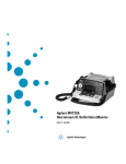
M4735A Defibrillator/Monitor
Notice
About This Edition
WARNING
Medical Device Directive
Edition 1
Radio Frequency (RF) interference
from nearby transmitting devices may
seriously degrade performance of the
M4735A. Electromagnetic compatibility with surrounding devices should be
assessed prior to using the defibrillator.
The M4735A Defibrillator/Monitor
complies with the requirements of the
Medical Device Directive 93/42/EEC
Printed in the USA
Publication number M4735-90900
The information in this manual applies
to the M4735A Heartstream XL
Release A.0.0. This information is subject to change without notice.
Agilent Technologies shall not be liable
for errors contained herein or for incidental or consequential damages in connection with the furnishing,
performance, or use of this material.
Edition History
Edition 1, July, 2000
Copyright
Copyright © 2000
Agilent Technologies, Inc.
3000 Minuteman Road
Andover, MA 01810-1099 USA
(978) 687-1501
This document may not be photocopied,
reproduced, or translated to another language without prior written consent of
Agilent Technologies.
ii
CAUTION
Use of supplies or accessories other
than those recommended by Agilent
Technologies may compromise product
performance.
THIS PRODUCT IS NOT INTENDED
FOR HOME USE.
IN THE U.S., FEDERAL LAW
RESTRICTS THIS DEVICE TO SALE
ON OR BY THE ORDER OF A PHYSICIAN.
and carries the
0123 mark accord-
ingly.
Authorized EU-representative:
Agilent Technologies GmbH
Herrenbergerstrasse 130
D-71034 Boeblingen,
Germany
Fax: +49-7031-14-2346
Conventions
This manual uses the following text conventions:
Printed and On-Line
NOTE
Notes contain additional information on servicing this product.
CAUTION
Caution statements describe conditions or actions that can result in damage to
the equipment or loss of data.
WARNING
Warning statements describe conditions or actions that can result in personal injury
or loss of life.
Text
represents messages that appear on the display
Softkey
represents softkey labels that appear on the display
above or below the button to which they correspond
On-Line Only
Hypertext
represent hypertext links, which will display as blue;
click on the link to go to that destination, then click on
the destination to return.
iii
This page intentionally left blank
iv
Contents
Conventions
Printed and On-Line .......................................................................................................... iii
On-Line Only ................................................................................................................. iii
Hypertext .......................................................................................................................... iii
Introduction
Overview ....................................................................................................................1-1
Defibrillator/Monitor ...................................................................................................... 1-1
Batteries .......................................................................................................................... 1-2
Installation ...................................................................................................................... 1-2
Upgrades ......................................................................................................................... 1-2
Preventive Maintenance .................................................................................................. 1-2
Repair Philosophy ........................................................................................................... 1-3
Performance Verification and Safety Tests
Overview ......................................................................................................................... 2-1
Chapter Contents ............................................................................................................. 2-1
Mandatory Testing ......................................................................................................2-2
External Repairs/No Trouble Found ............................................................................... 2-2
Printer .............................................................................................................................. 2-3
Internal Repairs ............................................................................................................... 2-3
Test Matrix .................................................................................................................2-4
Test Equipment ...........................................................................................................2-8
Configuration and Diagnostic Modes ......................................................................2-10
Configuration Mode ...................................................................................................... 2-10
Diagnostic Mode ........................................................................................................... 2-11
The Software Support Tool ......................................................................................2-12
Using the Support Tool ................................................................................................. 2-12
Performance Verification .........................................................................................2-14
Visual Inspection ........................................................................................................... 2-15
Functional Checks ......................................................................................................... 2-16
Diagnostic Tests ............................................................................................................ 2-19
Safety Tests .................................................................................................................. 2-39
Battery Capacity Test .................................................................................................... 2-40
v
6/29/00
Contents
Troubleshooting
Overview ......................................................................................................................... 3-1
Chapter Contents ............................................................................................................. 3-1
Repair Philosophy ........................................................................................................... 3-1
Equipment Required ....................................................................................................... 3-1
Troubleshooting and Repair Methodology ................................................................3-2
Methodology Overview .................................................................................................. 3-2
Initial Assessment ......................................................................................................3-3
Diagnosing External Failures .....................................................................................3-4
Diagnosing Internal Failures ......................................................................................3-5
Troubleshooting Tables ..............................................................................................3-6
Using the Tables ............................................................................................................. 3-6
General Problems .......................................................................................................3-8
Unit Unresponsive .......................................................................................................... 3-8
Error Codes ................................................................................................................... 3-10
System Messages .......................................................................................................... 3-12
Momentary Messages ................................................................................................... 3-14
Audio Tones ................................................................................................................ 3-16
Extended Self Test Failures .......................................................................................... 3-17
Operational Problems ...............................................................................................3-18
ECG Monitoring ......................................................................................................... 3-18
SpO2 Monitoring .......................................................................................................... 3-20
Defibrillation and Cardioversion ................................................................................. 3-21
Pacing ............................................................................................................................ 3-24
Printer ........................................................................................................................... 3-25
Display .......................................................................................................................... 3-26
Audio ............................................................................................................................ 3-27
Keys ............................................................................................................................. 3-28
Battery and Charging Circuits ...................................................................................... 3-29
Data Card ...................................................................................................................... 3-30
Calling for Service ...................................................................................................3-31
United States of America .............................................................................................. 3-31
Canada .......................................................................................................................... 3-31
Other International Areas .............................................................................................. 3-31
Equipment Information ................................................................................................. 3-31
Removal and Replacement
Overview ......................................................................................................................... 4-1
Chapter Contents ............................................................................................................. 4-1
Servicing Notes ..........................................................................................................4-1
Key Components ............................................................................................................. 4-1
Removal, Handling, and Replacement ........................................................................... 4-2
Tool Requirements .......................................................................................................... 4-3
vi
Contents
Disposal .......................................................................................................................... 4-3
External Assemblies ...................................................................................................4-4
User-replaceable Parts and Accessories .......................................................................... 4-5
User Maintenance ........................................................................................................... 4-5
Printer Assembly ............................................................................................................. 4-6
Battery Cover ................................................................................................................ 4-10
Main Fuse ..................................................................................................................... 4-12
Battery Eject Assembly ................................................................................................ 4-14
Data Card Door ............................................................................................................. 4-16
Energy Select Knob .................................................................................................... 4-17
Paddle Holders .............................................................................................................. 4-18
Labels ............................................................................................................................ 4-20
Label Descriptions ........................................................................................................ 4-20
Removing and Replacing Labels .................................................................................. 4-22
Opening the Case .....................................................................................................4-24
Discharge the Power Supply Capacitors ...................................................................... 4-24
Separate the Case ........................................................................................................ 4-26
Discharge the Defibrillator Capacitor .......................................................................... 4-30
Identifying Internal Subassemblies ............................................................................... 4-32
Internal Assemblies - Top Case ................................................................................4-33
Lithium Backup Battery ................................................................................................ 4-34
Control PCA ................................................................................................................ 4-36
Shield Plate ................................................................................................................... 4-40
Keyscan PCA ................................................................................................................ 4-42
Bezel Assembly .......................................................................................................... 4-48
Energy Select Switch .................................................................................................... 4-52
...................................................................................................................................... 4-53
Display Assembly ......................................................................................................... 4-54
Parameter PCA ............................................................................................................. 4-56
SpO2 PCA .................................................................................................................. 4-58
ECG Connector ............................................................................................................. 4-60
SpO2 Connector ............................................................................................................ 4-62
Speaker ....................................................................................................................... 4-64
AC Mains Connector .................................................................................................... 4-66
ECG Out (Sync) Connector .......................................................................................... 4-69
Pacer Keypad ................................................................................................................ 4-70
Replacement Top Case .................................................................................................. 4-75
Internal Assemblies - Bottom Case ..........................................................................4-79
Battery PCA .................................................................................................................. 4-80
Defibrillator Capacitor .................................................................................................. 4-84
Power PCA ................................................................................................................... 4-86
AC Power Module ........................................................................................................ 4-90
Patient Connector .......................................................................................................... 4-94
Replacement Bottom Case ............................................................................................ 4-97
Closing the Case .......................................................................................................4-99
vii
Contents
Replacement Parts
Overview ......................................................................................................................... 5-1
Chapter Contents ............................................................................................................. 5-1
Ordering Replacement Parts .......................................................................................... 5-1
Ordering Supplies and Accessories ................................................................................ 5-1
Key Components ........................................................................................................... 5-2
Calling for Service .....................................................................................................5-3
United States of America
........................................................................................... 5-3
Canada ........................................................................................................................ 5-3
Other International Areas ............................................................................................ 5-3
Special Tools ..............................................................................................................5-4
M4735A Unit Exchange Program ..............................................................................5-5
Replacement Parts Tables ...........................................................................................5-6
Electrical Assemblies .................................................................................................5-7
Control PCA ................................................................................................................... 5-7
Other Replacement PCAs ............................................................................................... 5-8
Other Electrical Assemblies ........................................................................................... 5-8
Individual Electrical Parts ............................................................................................... 5-9
Mechanical Assemblies ............................................................................................5-10
Bezel Assembly ............................................................................................................ 5-10
Pacer Keypad Assembly ............................................................................................... 5-11
Other Mechanical Assemblies ...................................................................................... 5-12
Connector Assemblies .................................................................................................. 5-12
Individual Mechanical Parts ......................................................................................... 5-13
Labels .......................................................................................................................5-14
Instruction Label Sets ................................................................................................... 5-14
Case Label Sets ............................................................................................................. 5-16
Other Labels ................................................................................................................. 5-17
Supplies & Accessories ............................................................................................5-18
Key Components ......................................................................................................5-21
Theory of Operation
Overview ......................................................................................................................... 6-1
PCA Descriptions .......................................................................................................6-2
Control PCA ................................................................................................................... 6-2
Power PCA ..................................................................................................................... 6-3
Parameter PCA ............................................................................................................... 6-3
Keyscan PCA .................................................................................................................. 6-3
SpO2 PCA ....................................................................................................................... 6-4
Battery PCA .................................................................................................................... 6-4
Battery ............................................................................................................................. 6-4
AC Power Module .......................................................................................................... 6-4
Printer .............................................................................................................................. 6-4
viii
Contents
System Level Interconnections ..................................................................................6-5
System Functional Descriptions .................................................................................6-6
Signal and Data Flow ...................................................................................................... 6-6
ECG Monitoring Functions ............................................................................................ 6-7
Patient impedance functions ........................................................................................... 6-7
SpO2 Monitoring Functions ........................................................................................... 6-8
Defibrillation Functions .................................................................................................. 6-9
Pacing Functions ........................................................................................................... 6-11
Audio Functions ............................................................................................................ 6-11
Display Functions ......................................................................................................... 6-11
Indicator Functions ....................................................................................................... 6-11
Key Functions ............................................................................................................... 6-11
Energy Select Switch .................................................................................................... 6-12
Printing Functions ......................................................................................................... 6-12
Battery/Power Functions ............................................................................................... 6-12
Lithium Backup Battery ................................................................................................ 6-15
Data Card ...................................................................................................................... 6-15
Specifications
Overview ......................................................................................................................... 7-1
Specifications .............................................................................................................7-1
Defibrillator .................................................................................................................... 7-1
ECG Monitoring ............................................................................................................. 7-3
Display ............................................................................................................................ 7-4
Battery ............................................................................................................................. 7-4
Thermal Array Printer ..................................................................................................... 7-5
Noninvasive Pacing ........................................................................................................ 7-6
SpO2/Pulse Oximetry ...................................................................................................... 7-6
Event Storage .................................................................................................................. 7-6
General ............................................................................................................................ 7-7
Environmental ................................................................................................................. 7-7
Waveforms - 150J ......................................................................................................7-8
Waveforms - 200J .................................................................................................7-11
Symbol Definitions ..................................................................................................7-14
Safety Considerations ...............................................................................................7-16
Electromagnetic Compatibility ................................................................................7-19
Reducing Electromagnetic Interference ........................................................................ 7-19
Restrictions for Use ...................................................................................................... 7-20
Immunity Level ............................................................................................................. 7-20
ix
Contents
This page intentionally left blank.
x
1
Introduction
This Service Manual provides the information needed to successfully service the Agilent M4735A Heartstream XL Defibrillator/Monitors. The intended users of this manual are technical personnel who have been trained in the safe and proper servicing of
the M4735A. 1
Overview
In this chapter, you’ll find general information that you should become familiar with before servicing the M4735A. Detailed information regarding controls, operation, and capabilities of the instrument can be found in the User’s
Guide (M4735-91900) that was shipped with the product. We recommend
you review the User’s Guide before servicing this device. This Service Manual assumes you are familiar with the controls and with basic operations.
Defibrillator/Monitor
The M4735A is a biphasic, semi-automatic external defibrillator. This portable, lightweight device offers two modes of operation for defibrillation:
l
Semi-Automatic External Defibrillation (AED) Mode
l
Manual Mode
In AED Mode, the M4735A analyzes the patient’s ECG and advises the clinician whether or not to deliver a shock. Defibrillation is performed through
multifunction defib electrode pads.
In Manual Mode, the M4735A turns control of the defibrillation process over
to the clinician. The clinician analyzes the patient’s ECG, decides if defibrillation is advised, and determines the energy setting for defibrillation. Defibrillation is performed either through multifunction defib electrode pads or through
paddles.
Manual Mode also allows the clinician to perform synchronized cardioversion
and offers optional noninvasive pacing (using a monophasic waveform).
ECG monitoring can be accomplished in either mode using one of 3 methods:
l
ECG from the defib pads
l
3-lead ECG using separate monitoring electrodes
l
Optional 5-lead ECG using separate monitoring electrodes.
Optional pulse oximetry (SpO2) monitoring is available in both modes, as
well.
The M4735A automatically stores critical events, such as shocks and alarm
violations, in its internal memory. An Event Summary may be printed at any
time. The M4735A also enables you to store data and events on an M3510A
1-1
6/29/00
1
Overview
Data Card for downloading to the CodeRunner Web Data Management System.
Batteries
The M4735A is powered by a rechargeable Sealed Lead Acid (SLA) battery
(M3516A). Proper care of these batteries will ensure that they have the
energy required to operate the M4735A and deliver the appropriate therapy
(See "Battery Maintenance" section in User’s Guide).
NOTE
The defibrillator will take longer to charge when powered with AC without a
battery installed. To ensure optimal performance, always have a fully charged
battery in the defibrillator, even when using AC power.
Installation
The M4735A does not require installation. The User’s Guide describes the
setup required before placing the device into service, as well as configuration
options.
Upgrades
Upgrades are available to add specific functionality to units in the field. As of
the publication of this manual, these upgrades are:
l
M4738A Pacing Upgrade (adds pacing).
l
M4739A SpO2 upgrade. (adds SpO2).
Consult your sales representative or dealer or distributor for the latest details.
Preventive Maintenance
Preventive maintenance and periodic operational checks are intended to be
performed by the user. Both topics are covered in the Maintenance chapter of
the User’s Guide.
1-2
Introduction
Overview
Repair Philosophy
Defibrillator/Monitor
The repair philosophy of the M4735A is subassembly replacement. Examples
of subassemblies are the printer, the Control Printed Circuit Assembly (PCA),
and selected connectors and other items. Repairs that involve replacing components on a PCA are not supported.
CAUTION
Individual component replacement should not be attempted outside of a factory authorized repair facility. Component level repair is extremely difficult
due to the extensive use of surface mount technology and the high parts-density on the circuit boards. Unauthorized component replacement can impair
performance of the M4735A.
Batteries
The repair philosophy for the SLA battery (M3516A) is unit replacement.
These items are not repaired in the field.
For information on ordering replacements, see "Supplies & Accessories" on
page 5-18.
M4735A Service Manual
1-3
1
Overview
This page intentionally left blank.
1-4
Introduction
2
Performance Verification and Safety Tests
Overview
This chapter describes the tests and inspections required to verify performance of the M4735A Portable Defibrillator/Monitor.
Chapter Contents
The major sections of this chapter are as follows:
Section
Page
Mandatory Testing
2-2
Test Matrix
2-4
Test Equipment
2-8
Configuration and Diagnostic Modes
2-10
The Software Support Tool
2-12
Performance Verification
2-14
2-1
6/29/00
2
Mandatory Testing
Mandatory Testing
The Performance Verification Tests in this chapter are intended to verify
proper operation of the M4735A following repair. The level of testing
required corresponds to the type of repair performed, and is divided into 3 categories: External/No Trouble Found, Printer Replacement, and Internal
Repairs. Each of these categories is described below.
External Repairs/No Trouble Found
External Repairs are those involving the repair or replacement of one or
more of the items below. No Trouble Found applies when no malfunction
can be found, or when the problem appears to be due to improper use. In
either situation, the key point is that the case has not been opened.
l
External paddles
l
Internal paddles and/or adapter cable
l
Paddle holders
l
Pads adapter cable
l
ECG cable
l
SpO2 cable or sensor
l
Battery
l
Labels
l
AC Power cord
l
Consumables (ECG monitoring electrodes, multifunction defibrillation pads, printer paper)
l
Main fuse (on Battery PCA)
l
Data Card Door Assembly
l
Battery Eject Assembly
The following testing is required after an External Repair or when the outcome of the service is No Trouble Found (when the case has not been
opened):
2-2
l
Perform the Visual Inspection (page 2-15).
l
Run the Extended Self Test (page 2-22).
l
Print and Verify the System Log (page 2-20).
Performance Verification and Safety Tests
Mandatory Testing
Printer
If the printer was replaced, and the case was not opened, the following tests
are required:
l
Perform the Visual Inspection (page 2-15).
l
Run the Extended Self Test (page 2-22).
l
Run the Printer Test (page 2-27).
l
Print and Verify the System Log (page 2-20).
2
Internal Repairs
If the case was opened (regardless of what the repair involved), all of the Performance Verification Tests must be performed, beginning with "Visual
Inspection" on page 2-15.
M4735A Service Manual
2-3
Test Matrix
Test Matrix
The matrix in Table 2-1 summarizes performance verification tests and
inspections for the M4735A; including test name, test or inspection to perform, expected test results, and data to record.
Table 2-1 Performance Verification and Safety Tests
Test Group Name
Test or Inspection to
Perform
Expected Test Results
Data to Record
x = p (pass) or f(fail)
Visual Inspection
(V)
Inspect unit, accessories,
cables, etc. as described
on page 2-15.
• No unusual damage, no
corrosion: x=p.
V:x
Example V:p
Functional
Checks (F)
In normal Operating Mode,
perform the following functional checks:
• All functions respond as
expected
F:x
Example F:p
• ECG (page 2-16).
• Waveform clear on display;
HR correct on display; HR
alarm works
• Shock Advisory (page 217).
• Shock Advised only when
appropriate
• Synchronized Cardioversion (page 2-18).
• Shock delivered with correct timing
• SpO2 (page 2-18).
• 95% -100%
Extended Self
Test (X)
In Diagnostic Mode, run
the Extended Self Test
(page 2-22). Includes Data
Card Test and time/date
check.
"Pass" reported on all tests
applicable to the device configuration and options: x=p.
X:x
Example X:p
User Interface
Tests (U)
• In Diagnostic Mode, run
the following tests (page
2-25):
All responses as expected.
U:x
Example: U:p
• Controls Test
• All keys respond as
expected
• Display Test
• Visual Pass assessment by
service personnel
• Audio Test
• Audio Pass assessment by
service personnel.
• Printer Test
• Print quality: visual Pass
assessment by service personnel
• Print speed: 25 mm ± 5%
(1.25mm)
2-4
Performance Verification and Safety Tests
Test Matrix
Table 2-1 Performance Verification and Safety Tests
Test or Inspection to
Perform
Test Group Name
ECG Tests (E)
Expected Test Results
In Diagnostic Mode, run
the ECG Tests (page 2-29):
All data within limits, all
checks pass: x=p
• Status messages (lead,
pad, DSP)
• "Good" displayed for all
three
• DC offset
• Ignore - used only in factory manufacturing.
Data to Record
x = p (pass) or f(fail)
E: aaaa,bbbb,cc,dd,
ee,ffff,x
Example:
E:1000,1000,20,20,
50,2000,p
2
Amplifier gain
• Pads Peak to Peak (Monitor) - aaaa
• 1000mV ±10%
• Leads Peak to Peak (Diagnostic) - bbbb
• 1000mV ±10%
Amplifier noise
• Leads Peak to Peak (Diagnostic) - cc
• 0 ± 30uV
• Pads Peak to Peak (Monitor) - dd
• 0 ± 30uV
PCI measurement
Pacing Test (P)
• PCI - Paddles in Pockets –
ee
• 50 ± 30 Ω
• PCI - Paddles open – ffff
• > 1250 Ω
In Diagnostic Mode, run
the Pacing Test (page 233):
P:aa,bbb
Example: P:31,198
• 30 mA – aa
• 30 mA ± 5 mA
• 200mA – bbb
• 200mA± 20 mA
M4735A Service Manual
2-5
Test Matrix
Table 2-1 Performance Verification and Safety Tests
Test Group Name
Test or Inspection to
Perform
Defibrillator Test AC Power (DA)
(if AC Power used
in normal operation)
Using only AC power,
enter Diagnostic Mode
and run the Defibrillator
Test (AC Power at 200J)
(page 2-35):
Expected Test Results
Data to Record
x = p (pass) or f(fail)
DA:aaa,bbbbb,ccc,dd
Example:
DA:198,13000,195,48
Measured by
Defibrillator Analyzer:
• Delivered energy - aaa
• 200 ± 30J
Displayed by
M4735A:
Defibrillator Test Battery Power
(DB)
• Available Energy after
Shock
•0
• Msec to charge – bbbbb
• < 15000 msec
• Delivered energy - ccc
• Actual delivered energy
(aaa) ±7%
• Impedance - dd
• 42 to 57 Ω
• Defib errors
• None (0)
Using only battery power,
enter Diagnostic Mode
and run the Defibrillator
Test (Battery Power at
200J) (page 2-36).
DB:aaa,bbbb,ccc,dd
Example:
DB:198,2545,200,50
Measured by
Defibrillator Analyzer
• Delivered energy - aaa
• 200 ± 30 J
Displayed by
M4735A
Defibrillator Disarm Test (D)
2-6
• Available Energy after
Shock
•0
• Msec to charge – bbbb
• < 3000 msec
• Delivered energy - ccc
• Actual delivered energy
(aaa) ±7%
• Impedance - dd
• 42 to 57 Ω
• Defib errors
• None (0)
Enter Diagnostic Mode
and run the Defibrillator
Disarm Test (page 2-38)
All readings as expected:
x=p
D:x
Example: D:p
Performance Verification and Safety Tests
Test Matrix
Table 2-1 Performance Verification and Safety Tests
Test or Inspection to
Perform
Test Group Name
Safety Test (S)
Expected Test Results
Test both leads and pads,
and indicate test results
as follows:
External Leads: t=C
External Pads: t=B
Data to Record
x = p (pass) or f(fail)
S:aaa,bbbb,
t,ccc,ddd,eeee,fff,ggg;
t,ccc,ddd,eeee,fff,ggg
Example: S:125,150,
C,10,40,40,10,40;
B,90,150,2500,90,250
Earth Leakage
2
Earth Leakage
(Normal Condition) - aaa
< 500 uA (< 300 uA UL)
Earth Leakage
(Single Fault) - bbbb
< 1000 uA
Patient Lead Leakage
CF/ BF Applied Parts
• Source
(Normal Condition) - ccc
< 10 uA/100 uA
• Source
(Single Fault Condition) ddd
< 50 uA/500 uA
• With Mains on applied part
(Single Fault condition) eeee
< 50 uA/5000 uA
• Auxiliary
(Normal Condition) - fff
< 10 uA/100 uA
• Auxiliary
(Single Fault Condition) ggg
< 50 uA/500 uA
Note: All leakage current
tests include both Normal
and Reverse Polarity Conditions.
Report worst case values.
Note: When recording test results, separate results within a test by commas; separate tests by a semicolon (;); and
use no empty spaces. For example:
V:x;F:x;X:x;U:x;E: aaaa,bbbb,cc,dd,ee,ffff,x;P:aa,bbb;
DA:aaa,bbbbb,ccc,dd;DB:aaa,bbbb,ccc,dd;D:x;
S:aaa,bbbb,t,ccc,ddd,eeee,fff,ggg;t,ccc,ddd,eeee,fff,ggg
V:p;F:p;X:p;U:p;E:1000,1000,20,20,50,2000,p;P:31,198;
DA:198,13000,195,48;DB:198,2545,200,50;D:p;
S:125,150,C,10,40,40,10,40;B,90,150,2500,90,250
M4735A Service Manual
2-7
Test Equipment
Test Equipment
Table 2-2 lists the equipment needed to perform the Performance Verification
tests, and provides specifications for commercially available analyzers and
simulators. Test equipment is called out within each test procedure when
needed. In addition, a digital voltmeter is also useful.
A 50 ohm test load is available from Agilent Technologies (M1781A).
Table 2-2 Equipment List
Equipment/Test
Specifications
ECG Simulator
Calibrated Leads ECG simulator
• Amplitude accuracy
±2%
• Rate accuracy
±2%
Calibrated Paddles ECG simulator
• Amplitude accuracy
±2%
• Rate accuracy
±2%
Defibrillator Analyzer
Waveform compatibility
Meets all specs below using biphasic
truncated exponential waveform.
Load resistance:
50 Ω ±1% (non-inductive)
Maximum energy:
≥ 200 joules
Maximum voltage:
≥ 2500 V
Maximum current:
≥50 A
Measurement accuracy:
2-8
• ≥ 20 joules:
≤ ±2% of reading
• < 20 joules:
≤ ±0.4 joules
Cardioversion measurement range:
–150 to +150 ms
Performance Verification and Safety Tests
Test Equipment
Table 2-2 Equipment List
Equipment/Test
Specifications
Pacer tester
Load impedance:
≤400 Ω
Current measurement accuracy
• 30 mA–50 mA:
<±2 mA
• 50 mA–200 mA:
<±4%
2
Rate measurement accuracy
• 40–180 ppm:
<±0.5%
Waveform duration accuracy:
• 40–180 ppm:
M4735A Service Manual
±1ms
2-9
Configuration and Diagnostic Modes
Configuration and Diagnostic Modes
The instructions below describe how to enter Configuration Mode and Diagnostic Mode.
Configuration Mode
These instructions describe briefly how to use Configuration Mode. See the
User’s Guide for details on configuration settings and what effect they have.
1.
Power off.
Make sure the unit’s power is off.
2.
Insert a Data Card.
If you intend to save the configuration to a Data Card (or load the configuration from a Data Card), insert the Data Card now.
NOTE
To avoid possible confusion, designate one Data Card as the "Configuration
Card" and label it clearly. Keep this card physically separate from cards used
by the clinical staff for data storage.
3.
Enter Configuration Mode.
Press softkeys 4 and 5 at the same time, and hold them down while turning the power on. See Figure 2-1 for softkey numbering.
4.
5.
Select and manage Configuration choices.
l
To select a configuration, press the
and
softkeys to move up
or down the list until the desired Settings item is highlighted. Then
press the ENTER softkey to access those settings.
l
To print out a strip with all the current configuration choices, select
Print All Settings and press ENTER .
l
To store the configuration settings on a data card, select Save Settings
to Data Card and press ENTER . When prompted with Save Settings to
Data Card? press SAVE .
l
To load configuration settings from a Data Card, select Load Settings
from Data Card and press ENTER . When prompted with Load Settings
from Data Card? press LOAD .
Exit Configuration Mode.
To exit Configuration Mode, turn the unit off. Remove the Data Card.
2-10
Performance Verification and Safety Tests
Configuration and Diagnostic Modes
Figure 2-1 Softkey Numbers
Softkeys
4
5
6
7
2
Diagnostic Mode
These instructions describe how to enter Diagnostic Mode. Once in Diagnostic Mode, you can do the following:
1.
l
Print the System Log. See "System Log" on page 2-20.
l
Run the Extended Self Test. See "Extended Self Test" on page 2-22.
l
Run other Diagnostic Tests. See "Diagnostic Tests" on page 2-19.
Power off.
Make sure the unit’s power is off.
2.
Enter Diagnostic Mode.
Press softkeys 4 and 6 at the same time, and hold them down while turning the power on. See Figure 2-1 for softkey numbering.
3.
Wait for the unit to initialize.
This may take several seconds. The unit is ready to proceed when the
screen cursor responds to softkey inputs.
4.
Select the desired test or function.
To select a test, press the
and
softkeys to move up or down the
list until the desired test is highlighted. Then press the ENTER softkey to
start that test.
5.
Exit Diagnostic Mode.
To exit Diagnostic Mode, turn the unit off.
M4735A Service Manual
2-11
The Software Support Tool
The Software Support Tool
The Software Support Tool (M4735-87890) allows field service personnel to
perform 2 tasks: 1) to enable the SpO2 option, and 2) to program in the serial
number. These tasks need to be performed under the following circumstances:
l
The Control PCA has been replaced.
The Control PCA contains all the operating software, configured
for the installed hardware. It also contains the unit’s serial number,
which was programmed in during manufacturing.
The new Control PCA must be programmed to recognize the
hardware installed in this unit, and to contain that unit’s
serial number.
l
The unit has received an upgrade adding the SpO2 capability.
The added hardware will not be automatically recognized. The
Control PCA must be programmed to recognize the new hardware
installed.
Using the Support Tool
1.
2.
Prepare the unit.
a.
Have unit power off, and have either a fresh battery installed or the
AC power cord plugged in.
b.
Insert the Support Tool data card into the unit.
c.
Turn unit power on.
Follow the screen prompts.
a.
Select whether SpO2 hardware is installed or not as appropriate.
b.
Program in the unit’s serial number.
c.
l
If this is an SpO2 upgrade, the serial number should already be
present. In this case, verify it against the factory-applied label on
the bottom of the case.
l
If this is a Control PCA replacement, program in the serial number found on the factory-applied label on the bottom of the case
using the softkeys as instructed on the screen. Be sure to program
it in accurately, as the serial number is used for all repair history
tracking.
Check all the displayed information carefully before proceeding.
l
2-12
If the displayed information is correct, follow the screen prompts
to save the configuration.
Performance Verification and Safety Tests
The Software Support Tool
l
If any of the information is incorrect, follow the prompts to NOT
save the configuration, then start over by powering the unit off,
then back on.
3.
Turn off the power and remove the Data Card.
4.
Check the customer configuration.
5.
a.
Turn the unit back on and enter Configuration Mode (see "Configuration Mode" on page 2-10).
b.
Print the configuration and check it against the printout from before
the servicing began. Reset the configuration (or load it from a Data
Card) as needed.
Verify performance.
Perform Performance Verification Testing as described in "Performance
Verification and Safety Tests" starting on page 2-1.
M4735A Service Manual
2-13
2
Performance Verification
Performance Verification
This section gives instructions for running Performance Verification tests on
the M4735A. The tests are sequenced to check more basic functions first, and
then build on that to check more complex functions. We recommend you
perform these tests in this sequence. If desired, you can make copies of the
Test Results Matrix (page 2-4) and use it to record results.
The Performance Verification tests include:
2-14
Section
Page
Visual Inspection
2-15
Functional Checks
2-16
Diagnostic Tests
2-19
Safety Tests
2-39
Battery Capacity Test
2-40
Performance Verification and Safety Tests
Performance Verification
Visual Inspection
1.
Inspect the unit.
Inspect the entire unit, especially paddles, power cord, printer, battery,
cables, and sensors for signs of the following.
l
Wear or damage to paddles, cables, and adapters.
l
Wear or damage to patient cables and associated strain reliefs.
l
Mechanical damage to case, membrane switches, speaker cover,
ambient light sensor cover, display window.
l
Loose or missing hardware.
l
Evidence of liquid spill. Check inside the printer bucket and
clean out any accumulation using gloves and an approved cleaner.
l
Residue on the thermal printhead.
l
Printer roller wear.
l
Wear or damage to power cord and associated strain relief.
l
Corrosion on connector pins, printer parts, or battery contacts.
Pass: Only normal wear, no damage serious enough to inhibit
performance. No corrosion visible.
2.
Check the consumables.
Check the ECG electrodes and defibrillator pads for freshness (data code
or expiration date) and condition.
Pass: Electrodes and pads are within their expiration date and
appear usable. Packaging is unopened and shows no tears or punctures.
No corrosion visible on connector sockets, electrodes, or pads.
M4735A Service Manual
2-15
2
Performance Verification
Functional Checks
The following functional checks exercise the basic functions of the defibrillator/monitor. They are intended as a broad check of the unit’s performance,
and are designed to complement (not replace) the Diagnostic Tests described
later.
If all elements of a test pass, record that test as a PASS and return to the main
diagnostic menu by pressing MAIN . If there is any failure, begin troubleshooting and repairing as needed. See "Troubleshooting" on page 3-1.
The Functional Checks include:
Check
Page
ECG Functional Checks
2-16
Shock Advisory Functional Check
2-17
Synchronized Cardioversion Functional
Check
2-18
Sp02 Functional Check
2-18
ECG Functional Checks
This section describes how to check the operation of the ECG functions. Each
of the ECG checks assumes the unit and the simulator are still set up as they
were at the end of the previous ECG check.
To check ECG display and Heart Rate (HR) functions:
1.
2.
Set up the simulator.
a.
Connect the ECG simulator to both the Pads input and the 3- or
5-lead ECG cable.
b.
Set the simulator for normal sinus rhythm (NSR), 1mV amplitude, at
some nominal rate (e.g., 60 bpm).
Set up the M4735A.
Set the M4735A to Manual operating mode (not Diagnostic Mode).
3.
Check the displayed ECG.
Using the LEAD SELECT softkey, verify that the display shows a normal
ECG with a clean baseline for both Pads and Lead II.
4.
Check the Heart Rate (HR).
Verify that the Heart Rate (HR) displayed is correct.
5.
2-16
Check Leads Off.
a.
Disconnect the ECG simulator from the pads cable and verify that the
display shows a dashed line in place of the waveform and that the unit
both alarms and gives the Pads Off message
b.
If using a 5-lead ECG cable, set the unit to monitor from the V lead.
Performance Verification and Safety Tests
Performance Verification
c.
Disconnect each of the ECG leads from the simulator one at a time,
and verify that the display shows a dashed line in place of the waveform and that the unit both alarms and gives the Leads Off message.
To check ECG printing functions:
6.
Reconnect the simulator.
Connect the simulator to the M4735A as described in step 1 above.
7.
Print a strip.
a.
Print a strip; verify that it shows a normal ECG with a clean baseline.
b.
Verify that the date, time, and configuration information printed at the
top of the strip is correct.
Shock Advisory Functional Check
This section describes how to check the Shock Advisory function.
1.
2.
Set up the simulator.
a.
Connect the ECG simulator to the pads cable.
b.
Set the simulator for normal sinus rhythm (NSR), 1mV amplitude, at
some nominal rate (e.g., 60 bpm).
Set up the M4735A.
Set the M4735A to AED Mode.
3.
4.
5.
WARNING
M4735A Service Manual
Check Shock Advisory with NSR.
a.
Press ANALYZE .
b.
Verify that the defibrillator responds with No Shock Advised.
Check Shock Advisory with Asystole.
a.
Set the simulator to Asystole (or turn the simulator off) and press
ANALYZE .
b.
Verify that the defibrillator still responds with No Shock Advised.
Check Shock Advisory with VF.
a.
Set the simulator to VF (Ventricular Fibrillation) and press
ANALYZE .
b.
Verify that the defibrillator responds with Shock Advised and charges
up to 150J. If the unit is configured to do so, verify that it automatically prints a strip of the event.
Do not discharge the stored energy unless you are certain the simulator contains a
50 ohm test load.
2-17
2
Performance Verification
c.
If the simulator contains a 50 ohm test load, discharge the stored
energy into the test load. If it does not, or you are not sure, wait until
the defibrillator reports Shock cancelled before proceeding.
Synchronized Cardioversion Functional Check
This section describes how to check the synchronized cardioversion function.
1.
2.
Set up the simulator and the analyzer.
a.
Connect the ECG simulator to the ECG cable. Connect the defibrillator analyzer to the pads cable.
b.
Set the simulator for normal sinus rhythm (NSR), 1mV amplitude, at
some nominal rate (e.g., 60 bpm).
Set up the M4735A.
Set the defibrillator to Manual Mode, and press
3.
.
Check Cardioversion.
a.
Verify that sync markers appear on the display, at the peak or on the
falling side of the QRS complex. Adjust the size of the displayed
ECG as needed to view it more clearly.
b.
Select an energy of 5 J. Press CHARGE then press and hold SHOCK
until the shock is delivered (at next QRS).
c.
Verify on the defibrillator analyzer that the shock was delivered, and
was 5J ±2J.
d.
If the unit is configured to do so, verify that it prints a strip with the
correct information on it (waveform, text).
e.
Verify on the defibrillator analyzer that the delay between the peak of
the QRS and the delivered shock was <60 msec.
Sp02 Functional Check
This check only needs to be performed if SpO2 is installed.
1.
Connect the sensor.
Attach the SpO2 transducer to your finger and connect it to the M4735A.
2.
2-18
Check SpO2.
a.
Activate Manual Mode and press the SpO2 softkey to turn SpO2 on.
b.
The SpO2 value displayed should be in the range of 95-100%. If the
value is less than 95%, check that your finger is fully inserted into the
sensor and properly positioned.
Performance Verification and Safety Tests
Performance Verification
Diagnostic Tests
The M4735A includes an extensive set of Diagnostic Tests, which test the
major hardware components of the defibrillator.
The Diagnostic Tests include:
M4735A Service Manual
Test
Page
System Log
2-20
Extended Self Test
2-22
User Interface Tests
2-25
ECG Tests
2-29
Pacing Test
2-33
Defibrillator Test (AC Power At 200 J)
2-35
Defibrillator Test (Battery Power At 200 J)
2-36
Defibrillator Disarm Test
2-38
2
2-19
Performance Verification
System Log
The System Log includes the unit’s serial number, hardware configuration,
and a listing of error codes. The System Log should be printed each time a
Performance Verification Test is run.
1.
Enter Diagnostic Mode.
See "Diagnostic Mode" on page 2-11.
2.
3.
Print the System Log.
a.
Select Print Log and press ENTER .
b.
The printer will print the System Log strip. See "Sample System Log
Printout" on page 2-21.
Check the System Log.
a.
b.
Check hardware and options.
l
Check the printout to verify the printed results are consistent with
the hardware in place. Check options installed (SpO2, pacing)
and the unit’s serial number (on the bottom of the case).
l
If the printout is not correct, investigate and resolve the source of
the mismatch. Then reset the hardware options and serial number
as needed using the Support Software Tool. See "The Software
Support Tool" on page 2-12.
Check for M4735A errors.
If there are device errors reported in the System Log:
2-20
l
Check the time and date stamps to see if they are recent errors or
not.
l
Consult Table 3-2 "Error Codes" on page 3-10 to identify the
errors.
l
Begin troubleshooting as needed (See "Troubleshooting" on page
3-1. )
Performance Verification and Safety Tests
Performance Verification
Figure 2-2 Sample System Log Printout
M4735A SYSTEM LOG
Firmware Versions
Error Codes
Main:
06
DSP:
02
196:
06.00
Key:
01
SpO2:
02.42 01.04
Language:
Serial Number:
19 MAY 2000
2
English
US01000241
Options:
Pacer
Shocks:
2
M4735A Service Manual
90007 18:33
SpO2
2-21
Performance Verification
Extended Self Test
The Extended Self Test checks that all internal processors are operating and
communicating with each other.
If all results are as described, the unit passes this test. Return to the main
Diagnostic Test menu by pressing MAIN .
If there is any failure, begin troubleshooting and repairing the unit as needed.
See "Troubleshooting" on page 3-1, and Table 3-6 "Extended Self Test Failures" on page 3-17.
Be sure the printer has paper and that the printer door is closed. No paper or
an open door will generate an erroneous Fail in the Timebase test.
NOTE
1.
Connect the test load to the pads cable.
2.
Access the Diagnostic Test menu.
See "Diagnostic Mode" on page 2-11.
3.
Run the test.
Select Extended Self Test and press ENTER . The printout should appear
similar to Figure 2-3.
Figure 2-3 Sample Extended Self Test Printout
M4735A EXTENDED SELF TEST
2-22
RAM:
Pass
ROM:
Pass
System:
Pass
Data Card:
Not Tested
CODEC:
Pass
IRDA:
Not Tested
Timebase:
Pass
Defib:
Pass
FE:
Pass
SpO2:
Pass
Pacer:
Pass
18:48
5/19/2000
Performance Verification and Safety Tests
Performance Verification
4.
Check the results.
a.
b.
Check the time and date.
l
Check the printout to verify that the time and date are correct.
l
If they are not, reset them using the Configuration Mode. See
"Configuration Mode" on page 2-10.
Check the test results.
The results of the following tests will appear on the display and
on the printout:
l
2
RAM
Tests the Read Only Memory (ROM).
l
ROM
Tests the Random Access Memory (RAM).
l
System
Tests the integrity of the core processing system and checks
the Lithium backup battery.
l
Data Card
The Data Card test writes a small file to the data card,
reads it back and checks it, then erases that file. If no
Data Card is present, the test result will be Not Tested.
l
CODEC
The processor turns on the CODEC (coding/decoding) chip
(used for voice prompts), and gets an acknowledgement
that it’s ready to receive data. It does not give the CODEC
actual data to process.
l
IRDA
Tests the infrared communications port. If no active
infrared device is within range, the test result will be Not Tested.
l
Timebase
The Timebase test compares the Real Time clock to the System
clock to check for discrepancies. It does not test the SpO2 clock
or the Biphasic clock.
M4735A Service Manual
2-23
Performance Verification
l
DEFIB
The Defib test charges the defibrillator capacitor and then
disarms it. It does not deliver the energy outside the unit.
The pads cable and test load must be connected for the test
to run; otherwise the test result will be Not Tested.
l
FE
The Front End (FE) test checks that the main processor is
communicating with the Digital Signal Processor (DSP), and that
the DSP is communicating with both ECG front ends (pads and
leads). It does not test the quality of the ECG measurement.
l
SP02 (if SpO2 option installed)
This tests that communication with the SpO2 PCA is working. It
does this by reading the software revision back from the PCA.
It does not test the quality of the SpO 2 measurement.
l
Pacer (if Pacing option installed)
The Pacer test has the Pacer deliver current into the test box, and
measures that the current delivered was what was expected. The
pads cable and test load must be connected for the test to run;
otherwise the test result will be Not Tested.
2-24
Performance Verification and Safety Tests
Performance Verification
User Interface Tests
The User Interface Tests exercise the functions that interact with the user.
Each of the User Interface tests assumes the unit and the simulator are still set
up as they were at the end of the previous User Interface check.
If all results are as described, the unit passes that test. Return to the main
Diagnostic Test menu by pressing MAIN .
If there is any failure, begin troubleshooting and repairing the unit as needed.
See "Troubleshooting" on page 3-1 and the following specific tables:
l
Table 3-11 "Operational Problems - Printer" on page 3-25.
l
Table 3-12 "Operational Problems - Display" on page 3-26.
l
Table 3-13 "Operational Problems - Audio Tones/Voice Prompts" on
page 3-27.
l
Table 3-14 "Operational Problems - Keys" on page 3-28.
2
To test the Controls (keys):
1.
Access the Diagnostic Test menu.
See "Diagnostic Mode" on page 2-11.
2.
Start the Controls Test.
Select Controls Test and press ENTER . The screen will display a map of
the front panel keys.
3.
Test the softkeys.
Press each of the numbered softkeys in turn. See Figure 2-1 on page 2-11
for numbering of softkeys. Each softkey number on the display should be
highlighted each time that key is pressed.
Don’t press Softkey #4 MAIN at this time. This will return you to the
Main diagnostic mode menu.
4.
Test the ECG and Audio keys.
Test each of the ECG Size and Volume keys. See Figure 2-1 on page 2-11
for location of these keys.Each key should show a highlighted + ("plus")
when the up arrow on the key is pressed, and show a highlighted ("minus") when the down arrow is pressed.
5.
Test the printer keys.
Test each of the printer control keys (Strip, Summary, and Mark). Each
corresponding label on the display should be highlighted each time that
key is pressed.
6.
Test the pacing keys.
Test each of the Pacing keys. The displayed labels for Pacer, Start/Stop
and Mode should be highlighted each time that key is pressed. The dis-
M4735A Service Manual
2-25
Performance Verification
played labels for Rate and Output should show a highlighted + ("plus")
when the up arrow on the key is pressed, and show a highlighted ("minus") when the down arrow is pressed.
7.
End the test.
Press Softkey #4 MAIN to return to the Main diagnostic mode menu.
To test the display:
1.
Run the Display Test.
Select Display Test and press ENTER .
The display should turn completely light, then completely dark, then a
light vertical bar should scroll across the screen from left to right.
2.
Test the LEDs.
The display will show a TEST LEDs softkey label. Press this softkey and
verify that the indicators in the Main and Pacing keypads each light in
turn. The AC Power and Batt Charge LEDs will not light as part of this test.
3.
End the test.
Press Softkey #4 MAIN to return to the Main diagnostic mode menu.
To test the audio output:
1.
Start the Audio Test.
Select Audio Test and press ENTER . The screen will display the Audio Test
menu.
2.
Select and run the desired test.
a.
Press the
and
softkeys to move up or down the list to select
the desired test. Then press ENTER to begin that test.
Check the Shutdown Warning and the Voice Prompt; the
other responses are given for reference. The results should
be as described below.
Press CANCEL to end that test and return to the main
audio test menu.
2-26
l
Message Alert - A repeating series of 3 short tones, followed by a
pause.
l
Heart Rate Alarm - 1 sustained tone of moderately high pitch.
l
Charge Done Tone - 1 sustained tone of lower pitch than the Heart
Rate Alarm.
l
Auto Disarm Warning - A repeating series of 1 short tone and a
pause.
Performance Verification and Safety Tests
Performance Verification
3.
l
Shutdown Warning - A repeating series of tones of alternating
high/low pitch.
l
Voice Prompt - Voice should be clear and understandable.
End the test.
Press Softkey #4 MAIN to return to the Main diagnostic mode menu.
To test the printer:
1.
a.
2.
3.
2
Start the Printer Test.
Select Printer Test and press ENTER .
Check the print quality.
a.
Verify that the test patterns on the strip are as indicated in
Figure 2-4.
b.
Check for white lines (printhead elements stuck off) or black lines
(printhead elements stuck on).
c.
Check area "A" for stray marks or lines.
d.
The area of Figure 2-4 labeled "C" contains printouts of all characters
and symbols. Verify that they are readable.
Stop the printout.
Press CANCEL to end the test and return to the main Diagnostic Test
menu.
4.
Verify the print speed.
Measure between the long tick marks (B in Figure 2-4) to verify paper
speed. Distance should be 25mm ± 5% (±1.25 mm).
5.
M4735A Service Manual
Check the printer status detection.
a.
Open the printer door and press the Strip key. The unit should sound
a series of 3 tones indicating a printer problem.
b.
Take out the paper, close the door, and press the Strip key. The unit
should sound a series of 3 tones indicating a printer problem.
2-27
Performance Verification
Figure 2-4 Printer Test Output
Diagonal lines
Vertical bars
Diamonds
2-28
Performance Verification and Safety Tests
Performance Verification
ECG Tests
These instructions describe how to test the ECG functions.
Each of the ECG tests assumes the unit and the simulator are still set up as
they were at the end of the previous ECG test.
If all results are as described, the unit passes that portion of the test. Return to
the main Diagnostic Test menu by pressing MAIN .
If there is any failure, begin troubleshooting and repairing the unit as needed.
See "Troubleshooting" on page 3-1 and Table 3-7 "Operational Problems ECG Monitoring (Pads or Leads)" on page 3-18.
1.
Start the test.
a.
Access the Diagnostic Test menu as described in "Diagnostic Mode"
on page 2-11.
b.
Select ECG Test and press ENTER .
c.
The display should look similar to Figure 2-5:
Figure 2-5 ECG Test Display
MAIN
ENTER
ECG TEST
Selected Lead:
Lead I
AC Line Filter:
60 Hz
Leads FE Status:
Good
Pads FE Status:
Good
DSP Status:
Good
DC Offset:
xxxx
On
Peak to Peak:
Diagnostic:
1050
Monitor:
1090
PCI:
2.
51
Off
Check the settings.
a.
AC Line Filter
The AC Line Filter should be set to the correct frequency
for your area.
If the setting is incorrect, access the Configuration Mode and correct
it. See "Configuration Mode" on page 2-10.
M4735A Service Manual
2-29
2
Performance Verification
b.
Selected Lead
This setting does not matter at this point. It will be changed later.
3.
Change the settings as needed.
a.
NOTE
The available choices for Selected Lead will depend on whether the unit is
configured for 3-lead or 5-lead ECG monitoring.
b.
NOTE
To temporarily change the settings of Selected lead or AC Line filter,
press the
and
softkeys to highlight the parameter, then press
(and release) ENTER to select it.
After a few seconds the highlighted selection will begin to blink, and
the
and
softkeys will allow you change the selection to
another of the values available. When the value you want is displayed, press ENTER to set that value.
These changes are only temporary, and will not override the configuration set
in Configuration Mode.
4.
Check the ECG Status messages.
The 3 status messages (Lead FE, Pad FE, DSP) should all be GOOD.
5.
l
The Leads FE test checks that communication is working between
the Leads Front End (FE) and the Digital Signal Processor (DSP).
l
The Pads FE test checks that communication is working between
the Pads FE and the DSP.
l
The DSP test checks that communication is working between the
DSP and the rest of the monitor.
DC Offset.
This test is for manufacturing use only and should be ignored.
6.
Test the ECG amplifier.
These tests measure both the gain and the noise of the two ECG amplifiers (Leads and Pads). Both use the Peak to Peak reading.
The Peak to Peak reading measures the peak to peak amplitude of the signal appearing on the selected ECG input. If the simulator’s calibrated
output is 1.0 mV, then the Peak to Peak reading should be 1000 ± 10%
(±100) for both Monitor and Diagnostic. If the simulator output is calibrated to some other value, the displayed value should be (1000 x simulator output) ±10%.
NOTE
2-30
The diagnostic frequency response is only available when using the ECG
Leads input. When the unit is set to Pads, the display will indicate dashes
(-----) for the Diagnostic Peak-to Peak value.
Performance Verification and Safety Tests
Performance Verification
a.
b.
Perform the amplifier gain test:
1.
Connect the ECG simulator to the pads cable. Set the simulator
output for sine wave, 2 Hz or 10 Hz, 1 mV peak-to-peak.
2.
Following the instructions under Step 3 on page 2-30 for changing settings, set Selected lead to Pads. Only the Monitor frequency
response will be available.
3.
Wait for the displayed value under Monitor to stabilize.
4.
The displayed value should be 1000 ±10% (±100). Record this as
"aaaa".
5.
Connect the ECG simulator to the ECG leads cable.
6.
Following the instructions under Step 3 on page 2-30 for changing settings, set Selected lead to Lead II.
7.
Wait for the displayed value under Diagnostic to stabilize.
8.
The displayed value should be 1000 ±10% (±100). Record this as
"bbbb".
Perform the amplifier noise test:
1.
Turn the simulator off. Leave it connected to the ECG cable, and
leave Selected lead set to Lead II.
2.
Wait for the displayed value under Diagnostic to stabilize.
3.
The displayed value should be 0 ± 30 uV. Record this as "cc".
If the unit exhibits more than 30 uV of noise, try repositioning the
cable or unit to minimize external interference. Also try various
combinations of having the ECG simulator turned on or off, and
(if applicable) whether the simulator is plugged into the AC
mains. Refer to Chapter 7 for more information about reducing
electromagnetic interference.
M4735A Service Manual
4.
Following the instructions under Step 3 on page 2-30 for changing settings, set Selected lead to Pads.
5.
Connect the simulator to the pads cable.
6.
Wait for the displayed value under Monitor to stabilize.
7.
The displayed value should be 0 ± 30 uV. Record this as "dd".
2-31
2
Performance Verification
7.
Test the PCI function.
This test checks the PCI (Patient Contact Indicator) function. The PCI
measurement is used to detect Pads Off and Paddles Off, and to light the
Patient Contact Indicator LEDs on PCI-equipped paddle sets. It is an
approximate measurement only - the impedance value used to adjust the
defibrillation waveform is a separate measurement, made during delivery
of the shock. See "Theory of Operation" beginning on page 6-1 for more
details.
2-32
a.
Connect a set of external paddles to the M4735A.
b.
If the PCI setting is On, turn it Off now by pressing the Volume Up and
Down arrow keys simultaneously. (See Figure 2-1 on page 2-11.)
c.
Remove the paddles from their holders and hold them firmly together,
face to face (metal-to-metal). Be sure the paddles clean and are making good contact with one another
d.
Turn the PCI setting On by pressing the Volume Up and Down arrow
keys simultaneously. (See Figure 2-1 on page 2-11.) The displayed
PCI value should now read 0.
e.
Place the paddles back in their holders. Be sure the metal contact clip
in the holder is clean and makes good contact with the face of the
paddle.
f.
The PCI measurement should now read 50 ohms ±30 ohms. Record
this as "ee".
g.
Remove the paddles from the holders and hold them apart. The PCI
measurement should read > 1250 ohms (full scale). Record this
as "ffff".
Performance Verification and Safety Tests
Performance Verification
Pacing Test
These instructions describe how to test the pacing function. This test only
needs to be run if the Pacing option is installed.
If all results are as described, the unit passes the test. Return to the main
Diagnostic Test menu by pressing MAIN .
If there is any failure, begin troubleshooting and repairing the unit as needed.
See "Troubleshooting" on page 3-1 and Table 3-10 "Operational Problems Pacing" on page 3-24.
1.
Set up the test.
2
a.
Connect the defibrillator to the Pacer tester.
b.
From the Diagnostic Menu, select Pacer Test and press ENTER . The
display should look similar to Figure 2-6.
Figure 2-6 Pacer Test Display
MAIN
PACER TEST
2.
Pacer Status:
Off
Selected Rate:
70
Selected Output:
30
Delivered mA:
0
Begin Pacing.
a.
Press
. The LED to the left of the button will illuminate.
The screen display of Pacer Status will change to Stopped.
b.
Press
6WDUW
6WRS
. Pacer Status will change to Pacing, and pacing
will begin at the default settings of 70 beats per minute (bpm) and 30
mA.
M4735A Service Manual
2-33
Performance Verification
3.
4.
5.
Check the default output.
a.
The Pacer should be delivering a current of 30mA ±5mA. Record the
delivered current indicated by the Pacer tester as "aa".
b.
The display on the M4735A should read the delivered current as measured by the Pacer tester ("aa") ±5 mA.
Test the maximum output.
Rate
a.
Using the
button, increase the rate to 180 bpm.
b.
Using the Output
c.
The Pacer should be delivering a current of 200mA ±20mA. Record
the delivered current indicated by the Pacer tester as "bbb".
d.
The display on the M4735A should read the delivered current as measured by the Pacer tester ("bb") ±20 mA.
button, increase the output to 200 mA.
End the test.
Turn off Pacing by pressing the
2-34
button.
Performance Verification and Safety Tests
Performance Verification
Defibrillator Test (AC Power At 200 J)
These instructions describe how to test the defibrillation function when powered only by AC power (no battery installed).
If all results are as described, the unit passes the test. Return to the main
Diagnostic Test menu by pressing MAIN .
If there is any failure, begin troubleshooting and repairing the unit as needed.
See "Troubleshooting" on page 3-1 and Table 3-9 "Operational Problems Defibrillation and Synchronized Cardioversion" on page 3-21.
1.
2.
3.
Set up the test.
a.
Turn defibrillator off and remove the battery. Connect the AC Power
cord.
b.
Connect the defibrillator analyzer to the pads cable. Set the analyzer
to measure delivered energy. If needed, reset the analyzer’s display to
read 0.
c.
Turn the defibrillator on, and from the Diagnostic Menu, Select the
Defib Meas Test and press ENTER .
Deliver a 200J shock.
a.
Use the Energy Select control to select 200J.
b.
Press the CHARGE softkey to charge the defibrillator.
c.
Press SHOCK .
Check the analyzer readings.
Read the delivered energy indicated by the defibrillator analyzer. It
should be 200J ±15% (±30J). Record as "aaa".
4.
Check the values displayed by the M4735A.
The results displayed by the M4735A should be as follows:
M4735A Service Manual
Available Energy:
Not recorded - failure if >0.
ms to Charge:
<15000
Delivered Energy:
Actual delivered energy ("aaa") ±7%(Record as "ccc")
Impedance:
42 to 57 ohms
Peak Current:
Ignore. Derived from same measurements as delivered
energy and impedance
Defib Errors:
Not recorded - failure if any reported.
Shock Counter:
Disregard.
(Record as "bbbbb")
(Record as "dd")
2-35
2
Performance Verification
Defibrillator Test (Battery Power At 200 J)
These instructions describe how to test the defibrillation function when powered only by a fully charged battery, with no AC power connected.
If all results are as described, the unit passes the test. Return to the main
Diagnostic Test menu by pressing MAIN . If there is any failure, begin troubleshooting and repairing the unit as needed. See "Troubleshooting" on
page 3-1 and Table 3-9 "Operational Problems - Defibrillation and Synchronized Cardioversion" on page 3-21.
1.
2.
3.
Set up the test.
a.
Turn the defibrillator off. Insert the battery and disconnect the AC
Power cord.
b.
Connect the defibrillator analyzer to the pads cable. Set the analyzer
to measure delivered energy. If needed, reset the analyzer’s display to
read 0.
c.
Turn the defibrillator on, and from the Diagnostic Menu, Select the
Defib Meas Test and press ENTER .
Deliver a 200J shock.
a.
Use the Energy Select control to select 200J.
b.
Press the CHARGE softkey to charge the defibrillator.
c.
Press SHOCK .
Check the analyzer readings.
Read the delivered energy indicated by the defibrillator analyzer. It
should be 200J ±15% (±30J). Record as "aaa".
4.
Check the values displayed by the M4735A.
The results displayed by the M4735A should be as follows:
2-36
Available Energy:
Not recorded - failure if >0.
ms to Charge:
<3000
Delivered Energy:
Actual delivered energy ("aaa") ±7%(Record as "ccc")
Impedance:
42 to 57 ohms
Peak Current:
Ignore. Derived from same measurements as delivered
energy and impedance
Defib Errors:
Not recorded - failure if any reported.
(Record as "bbbb")
(Record as "dd")
Performance Verification and Safety Tests
Performance Verification
NOTE
If the "ms to Charge" measurement is too high (unit takes too long to charge),
verify that the battery is fully charged. If it is, the battery may simply be old.
The 3000 ms specification is defined for a new, freshly charged M3516A battery. Replace the battery with one that is new and fully charged, and repeat
the test.
2
M4735A Service Manual
2-37
Performance Verification
Defibrillator Disarm Test
These instructions describe how to test the disarm function.
If all results are as described, the unit passes the test. Return to the main
Diagnostic Test menu by pressing MAIN . If there is any failure, begin troubleshooting and repairing the unit as needed. See "Troubleshooting" on
page 3-1.
1.
2.
3.
Set up the test.
a.
Turn the defibrillator off. Insert the battery and connect the AC
Power cord.
b.
Connect the defibrillator analyzer to the pads cable. Set the analyzer
to measure delivered energy. If needed, reset the analyzer’s display to
read 0.
c.
Turn the defibrillator on, and from the Diagnostic Menu, Select the
Defib Meas Test and press ENTER .
Charge and Disarm a 200J shock.
a.
Use the Energy Select control to select 200J.
b.
Press the CHARGE softkey to charge the defibrillator.
c.
Press DISARM .
Check the analyzer readings.
Read the delivered energy indicated by the defibrillator analyzer. It
should be 0J or be blank.
4.
Check the values displayed by the M4735A.
The results displayed by the M4735A should be as follows:
2-38
Available Energy
Not recorded - failure if >0.
Msec to charge
Ignore - tested earlier
Delivered energy
Blank
Impedance
Blank
Peak current
Blank
Defib errors
Not recorded - failure if any reported.
Performance Verification and Safety Tests
Performance Verification
Safety Tests
This section covers tests of the defibrillator’s electrical safety.
Using the procedures called out by the manufacturer of the analyzer in use,
measure and record the following data. Only test at the AC Mains (line) voltage used in the customer’s facility - there is no need to test both 120VAC and
240VAC. Also, test both Normal and Reverse Polarity line connections, and
record the worst case value.
Earth Leakage
l
2
Normal Condition - < 500 uA (< 300 uA for UL)
Record as "aaa".
l
Single Fault Condition - < 1000 uA
Record as "bbbb".
Patient Lead Leakage
Test both Leads (C) and paddles/pads (B) inputs.
l
Source (Normal Condition) - < 10 uA (C), < 100 uA (B)
Record as "ccc".
l
Source (Single Fault Condition) - < 50 uA (C), < 500 uA (B)
Record as "ddd".
l
With Mains on Applied Part (Single Fault Condition) - < 50 uA (C),
< 5000 uA (B)
Record as "eeee".
l
Auxiliary (Normal Condition) - < 10 uA (C), < 100 uA (B)
Record as "fff".
l
Auxiliary (Single Fault Condition) - < 50 uA (C), < 500 uA (B)
Record as "ggg".
M4735A Service Manual
2-39
Performance Verification
Battery Capacity Test
The Battery Capacity Test is not part of the routine Performance Verification.
It is included here for reference only.
To perform a Battery Capacity Test:
1.
Turn the M4735A off.
2.
Label the unit.
Place a "Test in Progress" label on the unit to indicate to others that it may
not be used.
3.
Insert a charged battery.
If an AC power cord is connected, unplug it now.
4.
5.
Run the test.
a.
While pressing Mark , turn power on to start the test.
b.
Allow the test to proceed to completion. The test takes approximately
three hours and is complete when test results print out and the device
turns itself off.
Check results.
Review the test results and take the appropriate action, as follows:
Table 2-3 Battery Capacity Test Results
If
2-40
Then
Elapsed Time > 2.5 hours
and
Low Battery Time > 10 minutes
1. The battery passed the test.
2. Record "pass CT" and the date on
the label on the bottom of the battery.
3. Recharge the battery before use.
Elapsed Time < 2.5 hours
or
Low Battery Time < 10 minutes
1. The battery failed the test.
2. Record "fail CT" and the date on the
label on the bottom of the battery.
3. Discard the battery appropriately.
Performance Verification and Safety Tests
3
Troubleshooting
Overview
This chapter provides information for troubleshooting problems with the
M4735A.
Chapter Contents
The major sections of this chapter are as follows:
Section
Page
Repair Philosophy
3-1
Equipment Required
3-1
Troubleshooting and Repair Methodology
3-2
Troubleshooting Tables
3-6
Calling for Service
3-31
3
Repair Philosophy
The repair philosophy of the M4735A is subassembly replacement. Examples of subassemblies are the printer, the Control PCA, and selected connectors and other items. Repairs that involve replacing individual components on
a PCA are not supported.
CAUTION
Individual component replacement should not be attempted outside of a factory authorized repair facility. Component level repair is extremely difficult
due to the extensive use of surface mount technology and the high parts-density on the circuit boards. Unauthorized component replacement can impair
performance of the M4735A.
Equipment Required
Troubleshooting requires the same test equipment as does Performance Verification. See "Test Equipment" on page 2-8.
3-1
6/29/00
Troubleshooting and Repair Methodology
Troubleshooting and Repair Methodology
We recommend you follow the methodology described below to isolate and
repair problems with the M4735A:
Section
Page
Methodology Overview
3-2
Initial Assessment
3-3
Diagnosing External Failures
3-4
Diagnosing Internal Failures
3-5
Methodology Overview
Interview the User
If possible, talk directly with the user who reported the problem. Identify
what they were doing when the problem occurred, and exactly what happened. What was on the display? What tones or voice prompts were heard?
Were there operational problems?
Identify the Problem
First, evaluate the unit’s condition using the steps in "Initial Assessment" on
page 3-3. Then use "Diagnosing External Failures" on page 3-4 to identify
problems that can be resolved without further troubleshooting. Finally, if
needed use "Diagnosing Internal Failures" on page 3-5 to isolate the problem
to a particular subassembly.
If no trouble is found, proceed to the "Performance Verification and Safety
Tests" chapter for instructions on tests to run.
Perform the Repair
Follow the procedures in the "Removal and Replacement" chapter to replace
any defective subassemblies.
When the repair is complete, it is good practice to check the repair by attempting to reproduce the specific problem found. It is also advisable to print the
System Log again to check that no errors have been logged after the repair.
Test the Unit
Use the procedures found in the "Performance Verification and Safety Tests"
chapter to verify that the unit is operating properly overall. Be sure the testing
performed is appropriate for the level of repair.
3-2
Troubleshooting
Initial Assessment
Initial Assessment
Use the following steps to begin isolating the problem.
Attempt Power Up
Assess the unit’s overall condition by performing the following steps.
1.
Disconnect the AC Power cord (if connected).
2.
Insert a fully charged battery into the unit.
3.
If the unit is used with a Data Card, insert a new, empty M3510A Data
Card into the unit.
4.
Attempt to power up the unit by turning the Energy Select Switch to
either Manual On or AED ON.
Evaluate the Response
3
The unit will respond in one of the following 3 ways:
No response
IF
The unit emits no sounds, and no changes are visible on
the display.
THEN
Troubleshoot further using Table 3-1 on page 3-8.
("Unit Unresponsive").
Minimal response
IF
Unit provides only a slight response, such as a click or chirp
from the speaker, or a change in the brightness or the borders
of the display.
THEN
Replace the Control PCA (see "Removal and Replacement"
on page 4-1).
Return to this section and begin again with
"Attempt Power Up".
Powers Up
M4735A Service Manual
IF
The unit can generate tones or voice prompts, or display text
or graphics, or respond to keypresses.
THEN
Proceed to "Diagnosing External Failures" on page 3-4.
IF
The screen is blank except for an error message such as
Defib Failure - Cycle Power.
THEN
Proceed to "Diagnosing Internal Failures" on page 3-5.
3-3
Diagnosing External Failures
Diagnosing External Failures
Many times, a problem will be the result of external failures such as defective
cables, depleted batteries, or improper operation. Use the steps below to rule
out these external failures before looking for an internal failure in the unit.
Capture the Configuration Data
Store the unit’s configuration data on a Data Card or print out the current configuration, if possible. See "Configuration Mode" on page 2-10.
Print the System Log
Print out the System Log if possible, and use any error codes to help isolate
the problem. See "System Log" on page 2-20.
NOTE
The M4735A log of error codes only reports the last 10 errors. If new errors
are created at this stage they may overwrite the existing codes and valuable
clues to the reported problem might be lost. Therefore always attempt to print
the System Log before proceeding.
Rule out external components and improper use
Referring to Table 5-16 for Supplies and Accessories, make sure the unit has:
l
An undamaged, fully charged M3516A battery.
l
A new, dry roll of Agilent 40457C/D printer paper. Printer paper may
jam if paper is wet. Also, printer may be damaged if wet paper is
allowed to dry while in contact with the printer elements.
l
Cables and sensors which are approved by Agilent and known to be
good. Also make sure that all external cables are fully inserted in
their receptacles.
l
A new, empty Data Card of the correct type (M3510A). Plugging in
the wrong type of card (e.g., a modem card) can cause startup failures.
To help identify problems which may be caused by external components or by
improper use, refer to:
l
Table 3-3 ("System Messages") and Table 3-4 ("Momentary messages").
l
The individual tables describing Operational Problems associated
with each function (defibrillation, ECG, etc.). See "Troubleshooting
Tables" on page 3-6.
Proceed to Internal Failures
If none of the above resolves the problem, proceed to "Diagnosing Internal
Failures" on page 3-5.
3-4
Troubleshooting
Diagnosing Internal Failures
Diagnosing Internal Failures
The following steps will help you isolate an internal failure to a particular
subassembly.
Capture the Configuration Data
If not already captured, store the unit’s configuration data on a Data Card or
print out the current configuration, if possible. See "Configuration Mode" on
page 2-10.
Print the System Log
If not already printed, print out the System Log if possible, and use any error
codes to help isolate the problem. See "System Log" on page 2-20.
NOTE
The M4735A log of error codes only reports the last 10 errors. If new errors
are created at this stage they may overwrite the existing codes and valuable
clues to the reported problem might be lost. Therefore always attempt to print
the System Log before proceeding.
Run Self Tests
To run the Self Tests, perform the following steps:
1.
Enter Diagnostic Mode. See "Diagnostic Mode" on page 2-11.
2.
Run the Extended Self Test. See "Extended Self Test" on page 2-22.
3.
Run the individual Diagnostic Tests that are applicable to the problem.
Diagnostic Tests are described starting with "User Interface Tests" on
page 2-25.
Use the Troubleshooting Tables
Use the Tables provided starting on page 3-6 to isolate the problem based on
factors such as:
M4735A Service Manual
l
Error codes reported in the System Log (Table 3-2, page 3-10).
l
Extended Self Test failures (Table 3-6, page 3-17).
l
Operational problems (starting with Table 3-7 on page 3-18).
3-5
3
Troubleshooting Tables
Troubleshooting Tables
Tables are provided to cover the troubleshooting topics below.
General Problems
Page
Unit Unresponsive
3-8
Error Codes
3-10
System Messages
3-12
Momentary Messages
3-14
Audio Tones
3-16
Extended Self Test Failures
3-17
Operational Problems
Page
ECG Monitoring
3-18
SpO2 Monitoring
3-20
Defibrillation and Cardioversion
3-21
Pacing
3-24
Printer
3-25
Display
3-26
Audio
3-27
Keys
3-28
Battery and Charging Circuits
3-29
Data Card
3-30
Using the Tables
The tables provide both Possible Causes and Corrective Actions. Use them
as follows:
NOTE
3-6
l
The Possible Causes are arranged in order of the approximate probability of their occurrence. Investigate them in the order given.
l
For each Possible Cause, try the Corrective Actions listed. If the first
Corrective Action does not fix the problem, try the others in the order
listed.
l
If none of the Corrective Actions fixes the problem, then try the next
Possible Cause listed.
Before replacing any parts, check to see if the cables and flex circuits are
properly connected. See "Servicing Notes" on page 4-1.
Troubleshooting
Troubleshooting Tables
3
M4735A Service Manual
3-7
General Problems
General Problems
The folowing tables describe general or system-level problems. For problems
pertaining to a particular operation or function, see "Operational Problems"
on page 3-18.
Unit Unresponsive
Isolate the fault by following the steps in Table 3-1 below.
Before replacing any parts, check to see if the cables and flex circuits are
properly connected. See "Servicing Notes" on page 4-1.
NOTE
Table 3-1 Unit Unresponsive
Test
1. Connect AC Power to unit.
2. Turn on Power and
observe unit’s response.
Result
Corrective Actions
"AC Power’ indicator
turns GREEN.
Normal response.
None. Proceed to step 2.
’AC Power’ indicator
stays OFF.
No power in AC outlet.
Restore power.
Power cord defective.
Replace power cord.
AC Power Module
failure.
Replace AC Power Module.
Main fuse open.
1. Replace Main Fuse.
2. Replace Power PCA and
Main Fuse.
Open in battery wiring.
1. Check/replace Battery
PCA.
2. Check/replace wiring to
Power PCA.
Short or other failure
somewhere in unit.
Disconnect printer and display from Control PCA at
Control PCA. Then proceed to step 3.
Unit powers up to some
working state.
Unit still unresponsive.
3-8
Possible Causes
Troubleshooting
General Problems
3. Turn on Power and
observe unit’s response.
Unit powers up to some
working state.
Short in printer or display.
Isolate the fault by reconnecting one at a time and
powering up again. Then
replace the display or printer
as needed.
Unit still unresponsive.
Short or other failure
somewhere in unit.
1. Replace Control PCA.
2. Replace Power PCA.
3. Replace Parameter PCA.
If all above unsuccessful,
return unit for bench repair.
3
M4735A Service Manual
3-9
General Problems
Error Codes
The System Log provides error codes in 5 digit hexadecimal format, as shown
below.
NOTE
Before replacing any parts, check to see if the cables and flex circuits are
properly connected. See "Servicing Notes" on page 4-1.
Table 3-2 Error Codes
Error Code
Possible Causes
Corrective Actions
00000 - 00400
Defib failure - charging circuits.
1. Replace Power PCA.
2. Replace Control PCA.
01000
Defib failure - biphasic processor.
1. Replace Power PCA.
2. Replace Control PCA.
02000
Leads front end failure.
1. Replace Parameter PCA.
2. Replace Control PCA.
04000
Pacer failure.
Replace Power PCA.
08000
Processor error.
Replace Control PCA.
10000 - 1FFFF
System monitor failure.
Replace Control PCA.
20000 - 2FFFF
Front end failure.
1. Replace Control PCA.
2. Replace Parameter PCA.
30000 - 3FFFF
Pacer failure.
1. Replace Power PCA.
2. Replace Control PCA.
40000 - 4FFFF
Monitor processor failure.
1. Replace Parameter PCA.
2. Replace Control PCA.
50000 - 5FFFF
SpO2 problem.
1. Replace SpO2 PCA.
2. Replace Parameter PCA.
3. Replace Control PCA.
60000 - 6FFFF
Advisory Failure
Replace Control PCA.
80000 - 8FFFF
IRDA failure.
1. Replace Parameter PCA.
2. Replace Control PCA.
90000 - 90002
Self Test failure - RAM/ROM or Gate
Array.
Replace Control PCA.
90003
Self Test failure - Data Card circuits.
Replace Control PCA.
90004 and 90005
Self Test failure - Codec/time base.
Replace Control PCA.
90006
Self Test failure - SpO2.
1. Replace SpO2 PCA.
2. Replace Parameter PCA.
3. Replace Control PCA.
90007 and 90008
Self Test failure - Pacer or Defib.
1. Replace Power PCA.
2. Replace Control PCA.
3-10
Troubleshooting
General Problems
Table 3-2 Error Codes
Error Code
Possible Causes
Corrective Actions
90009
Self Test failure - Front End.
1. Replace Power PCA.
2. Replace Parameter PCA.
3. Replace Control PCA.
9000A
Lithium backup battery failure.
1. Replace lithium battery.
2. Replace Control PCA.
A0000-A7FFF
Data Card failure.
1. Replace Data Card.
2. Replace Control PCA.
A8000 - AFFFF
Data Archival error.
Replace Control PCA.
B0000 - BFFFF
Audio failure.
Replace Control PCA.
F0000 - F0001
RAM/ROM failure.
Replace Control PCA.
F0002
Demo Mode failure
Replace Control PCA.
F0003
Keyscanner failure
1. Replace Keyscan PCA.
2. Replace Control PCA.
F0004
System Communication error
Replace Control PCA.
M4735A Service Manual
3
3-11
General Problems
System Messages
System messages remain on the display until the specified action is taken or
no longer relevant. They are intended for the end user and appear in the
User’s Guide. A subset of the available messages is duplicated here for the
reference of the service person.
Before replacing any parts, check to see if the cables and flex circuits are
properly connected. See "Servicing Notes" on page 4-1.
NOTE
Table 3-3 System Messages
Message
Description
Corrective Action
Configuration Lost
The configuration is reset to the default
settings.
1. Reconfigure the M4735A.
2. If problem reoccurs, service the unit.
See "Troubleshooting" on page 3-1 and
Table 3-6 on page 3-17.
Data Card Disabled
The PC card is not in use because it is full,
incompatible, absent, removed during the
incident, or inserted after the M4735A was
turned on.
If possible, turn the M4735A off for more
than 2 minutes, then insert a new, empty,
M3510A Data Card and turn the device
on.
ECG Fault
The ECG data acquisition system failed
and data is unavailable from the 3- or 5lead monitoring electrodes.
Service the unit. See "Troubleshooting"
on page 3-1 and Table 3-7 on page 3-18.
Monitor Failure - Cycle
Power
An error has occurred in the monitoring
subsystem.
Turn power off, then on. If message reappears, service the unit. See "Troubleshooting" on page 3-1.
Low Battery
The battery has sufficient capacity remaining to provide only about ten minutes of
monitoring time and six shocks before the
M4735A shuts off.
Replace the battery with a fully charged
M3516A battery.
Leads Off
The monitoring electrodes are not applied
or are not making proper contact with the
patient.
Check that the monitoring electrodes are
properly applied.
The ECG cable is not connected.
Check that the ECG cable is properly connected.
The internal cable from the ECG connector to the Parameter PCA is disconnected
Check the internal cable.
Failure on the Parameter PCA.
Replace the Parameter PCA.
No Pads
The multifunction defibrillation electrode
pads are not properly connected to the
M4735A.
Check the pads cable connection.
No Paddles
In Manual Mode, no therapy cable is connected to the instrument.
Connect the cable.
Pads Cable Off
The pads cable is not connected to the
defibrillator.
Check that the pads cable connector is
locked in place.
Failure on Power PCA.
Replace Power PCA.
3-12
Troubleshooting
General Problems
Message
Description
Corrective Action
The pads are not making proper contact
with the patient.
Make sure the pads are properly applied
to the patient.
Failure on Power PCA.
Replace Power PCA.
Defib Failure - Cycle
Power
An error has occurred in the defibrillator
subsystem.
Turn power off, then on. If message reappears, service the unit. See "Troubleshooting" on page 3-1 and Table 3-9 on page 317.
50J Maximum
When using internal paddles, the maximum energy delivered is limited to 50J.
Select a lower energy.
Pacer Failure
The pacing system is not functioning.
Service the unit. See "Troubleshooting"
on page 3-1 and Table 3-10 on page 3-24.
Pacer Output Low
The pacer is delivering less current to the
patient than specified in the output current
setting.
Check the pads are applied properly
(patient impedance is high).
System Failure Service Unit
A serious malfunction has occurred.
Service the unit. See "Troubleshooting"
on page 3-1.
SpO2 Cable Off
The SpO2 cable is not connected to the
device.
Attach the SpO2 cable to the M4735A.
SpO2 Light Interf
The level of ambient light is so high that
the sensor cannot obtain an SpO2 reading, or the sensor or cable is damaged.
1. Cover the sensor with an opaque material.
2. Check the sensor and cable for damage; try another sensor and cable.
Non Pulsatile
The patient’s pulse is absent or too weak
to be detected.
1. Check that the sensor is applied properly.
2. Make sure the sensor site has a pulse.
3. Relocate the sensor to a site with
improved circulation.
4. Try another sensor.
SpO2 Low Signal
SpO2 signal is too low to give an accurate
reading.
1. Check the sensor is applied properly.
2. Try another sensor type.
SpO2 Noisy Signal
Excessive patient movement, electrical
interference, or optical interference is
present.
1. Minimize patient movement or apply the
sensor to a site with less movement.
2. Secure the sensor cable loosely to the
patient.
3. Reduce sources of electrical or optical
interference.
SpO2 Sensor Fail
The SpO2 cable is not connected to the
device; or the cable or sensor are broken.
1. Attach the cable to the M4735A.
2. Replace cable and/or sensor.
SpO2 Failure
A failure has occurred in the SpO2 circuitry.
Turn power off, then on. If message reappears, service unit. See "Troubleshooting"
on page 3-1.
System Failure - Cycle
Power
A serious error has occurred.
Turn power off, then on. If message reappears, service unit. See "Troubleshooting"
on page 3-1.
Pads Off
M4735A Service Manual
3-13
3
General Problems
Momentary Messages
Momentary messages are temporary and only appear on the display for a few
seconds. They are intended for the end user and appear in the User’s Guide.
A subset of the available messages is duplicated here for the reference of the
service person.
Before replacing any parts, check to see if the cables and flex circuits are
properly connected. See "Servicing Notes" on page 4-1.
NOTE
Table 3-4 Momentary messages
Message
Possible Cause
Corrective Action
Attach Leads
The user attempted to begin pacing in
Demand Mode without ECG leads
attached to the patient.
Attach leads to patient.
Use Leads
With paddles connected and selected as
the ECG input, the user attempted to activate Synchronized Cardioversion.
Use leads for ECG.
With no leads connected, the user connected paddles and selected them as the
ECG input, then connected the leads.
Use leads for ECG.
Attach Pads
The multifunction defib electrode pads are
not making proper contact with the patient.
1. Check the pads are applied to the
patient, as directed on the package.
2. Replace pads if the prompt continues.
Attach Paddles
The user attempted to charge the defib in
Manual Mode with no paddles connected.
Connect paddles.
Defib Disarmed
The defib is disarmed and no energy is
available, due to one of the following:
• The pads connection is compromised.
• Check the pads are applied to the patient
properly.
• The mode is changed from Manual to
AED while the defibrillator is charged.
• If a shock is indicated, deliver the shock
before changing modes.
•
SHOCK is not pressed within 30 seconds of the defibrillator being charged.
• To deliver a shock, press SHOCK within
30 seconds of the defibrillator being
charged.
•
DISARM is pressed.
• None.
No Shock Delivered
Patient impedance is too high or too low.
1. Make sure pads are applied properly.
2. Replace the pads.
3. Replace the pads cable.
Check Printer
Printer paper is absent or jammed; the
printer door is not closed properly.
1. Reload printer paper.
2. Make sure the door is closed properly.
Data Card Full
No data is being recorded on the Data
Card, due to one of the following:
• The incident is more than 2 hours in
duration, causing the Data Card to fill.
3-14
• None. A new Data Card can not be
inserted during an incident.
Troubleshooting
General Problems
Message
Possible Cause
Corrective Action
• An empty Data Card was not inserted for
the incident; the Data Card filled sooner.
• Use one empty Data Card per incident/
patient to decrease the chance of the
card filling.
Data Card Interrupted
No data is being recorded on the Data
Card, because the Data Card was
removed during an incident.
Remove card, turn power off, insert card,
turn power on.
Data Card Not In Service
No data is being recorded on the Data
Card, because the Data Card was
inserted while the M4735A was on.
None. A Data Card must be inserted prior
to turning the M4735A on for the current
patient.
Incompatible Data
Card
No data is being recorded on the Data
Card, because a Data Card other than the
M3510A is inserted.
Use only M3510A Data Cards.
No Data Card Present
A Data Card is not in the M4735A.
Turn the M4735A off and insert a Data
Card prior to the first event for the patient.
Key Inactive
The key pressed is currently inactive (i.e.
Use the appropriate mode for the key.
3DFHU
Stop Pacer
M4735A Service Manual
0RGH
3
is inactive in AED Mode).
is pressed while pacing pulses
are being delivered.
Stop pacing before changing the pacing
mode.
3-15
General Problems
Audio Tones
The M4735A emits tones to alert you to its status.
Before replacing any parts, check to see if the cables and flex circuits are
properly connected. See "Servicing Notes" on page 4-1.
NOTE
Table 3-5 Audio Tones
Tone
Meaning
Suggested Action
At power on, a low tone of approx. 1
second followed by a series of
higher pitched, short tones.
Normal power on sequence.
None needed.
At power on, a continuous beep of
about 7 seconds.
System failure - processors not
communicating.
Turn power off, then on. If problem
reoccurs, replace Control PCA.
At any time, a repeating tone that
alternates between two frequencies.
The unit emits this tone beginning 1
minute before shutdown due to low
battery charge.
1. Connect an AC Power Cord or
replace the battery with one that
is fully charged.
2. Replace the AC Power Cord.
3. Service the unit. See "Troubleshooting" on page 3-1.
3-16
Troubleshooting
General Problems
Extended Self Test Failures
Should the unit report a FAIL in the Extended Self Test, resolve it using the
solutions below.
Before replacing any parts, check to see if the cables and flex circuits are
properly connected. See "Servicing Notes" on page 4-1.
NOTE
Table 3-6 Extended Self Test Failures
Failure
Possible Cause
Suggested Solution
Failure on Control PCA.
Replace Control PCA.
Lithium backup battery failure.
Replace lithium battery.
Data Card full, or incompatible, or
defective.
Replace Data Card with new, empty
M3510A.
Failure on Control PCA.
Replace Control PCA.
Pacer
Defib
Failure on Power PCA.
Replace Power PCA.
Failure on Control PCA.
Replace Control PCA.
FE
Failure on Control PCA.
Replace Control PCA.
Failure on Power PCA.
Replace Power PCA.
Failure on Parameter PCA.
Replace Parameter PCA.
Failure on SpO2 PCA.
Replace SpO2 PCA.
Failure on Control PCA.
Replace Control PCA.
RAM
ROM
System
CODEC
IRDA
Timebase
System
FAIL 10
Data Card
SpO2
M4735A Service Manual
3
3-17
Operational Problems
Operational Problems
These tables describe problems that may arise with specific functions or operations while using the M4735A.
ECG Monitoring
The following table covers problems that might arise while monitoring ECG.
Before replacing any parts, check to see if the cables and flex circuits are
properly connected. See "Servicing Notes" on page 4-1.
NOTE
Table 3-7 Operational Problems - ECG Monitoring (Pads or Leads)
Symptom
Noisy trace - constant noise on the
baseline.
Possible Cause
Suggested Solution
Incorrect configuration - power line
frequency (50 or 60 Hz) or Filter settings.
Check/change configuration as
needed.
Nearby source of constant interference.
Try moving cable/leads; try relocating unit.
Failure in ECG front end.
Pads: Replace Power PCA.
Leads: Replace Parameter PCA.
Failure in signal processing circuits.
Replace Control PCA.
Nearby source of time-varying interference, such as radio transmitter
(paging, walkie-talkies) or X-Ray
system.
Try moving cable/leads; try relocating unit.
Failure in ECG front end.
Pads: Replace Power PCA.
Leads: Replace Parameter PCA.
Failure in signal processing circuits.
Replace Control PCA.
Noisy trace - low frequency, periodic.
More than one instrument connected to the patient and active.
Only have one active instrument on
the patient at a time.
Flat line - no waveform, no Leads
Off or Pads Off message.
Short in internal ECG wiring or front
end.
Pads:
1. Replace Power PCA.
2. Replace Patient Connector +
its internal cable.
Noisy trace - intermittent bursts of
noise or random spikes.
Leads:
1. Replace Parameter PCA.
2. Replace ECG connector +
internal ECG cable.
Failure in signal processing circuits.
3-18
Replace Control PCA.
Troubleshooting
Operational Problems
Table 3-7 Operational Problems - ECG Monitoring (Pads or Leads)
Symptom
Leads Off message even though
ECG cable has been replaced and
is properly connected to the simulator.
Pads Off message even though
pads cable has been replaced and
is properly connected to the simulator.
Trace distorted.
One or more ECG controls don’t
respond (e.g., select lead or ECG
size).
Poor Leads ECG signal quality.
M4735A Service Manual
Possible Cause
Suggested Solution
Open in internal Leads ECG wiring
or front end, due to:
Cable from ECG Connector to
Parameter PCA has bad connection.
Reconnect cable properly. See
"Servicing Notes" on page 4-1.
Defective ECG Connector or cable
to Parameter PCA.
Replace ECG Connector.
Defective Parameter PCA
Replace Parameter PCA.
Open in internal Pads ECG wiring or
front end, due to:
3
Cable from Patient Connector to
Power PCA has bad connection.
Reconnect cable properly. See
"Servicing Notes" on page 4-1.
Defective Patient Connector or
cable to Power PCA.
Replace Patient Connector + its
internal cable.
Defective Power PCA.
Replace Power PCA.
Failure in ECG front end.
Pads: Replace Power PCA.
Leads: Replace Parameter PCA.
Failure in signal processing circuits.
Replace Control PCA.
Failure in keypress detection/processing.
1. Replace Control PCA.
2. Replace Parameter PCA.
Failure in keys/connections.
Replace Top Case Assembly.
The monitoring electrodes are not
making proper contact with the
patient.
Check that the monitoring electrodes are properly applied. If necessary, prepare the patient’s skin
and apply new electrodes.
The monitoring electrodes are outdated or dried-out.
Check the date code on the electrodes. Do not open the electrode
package until immediately prior to
use.
Radio frequency interference (RFI)
is causing artifact.
Relocate or turn off equipment that
may be causing RFI.
3-19
Operational Problems
Table 3-7 Operational Problems - ECG Monitoring (Pads or Leads)
Symptom
Possible Cause
Poor Paddles/Pads ECG signal
quality.
QRS beeper inaudible or beeps do
not occur with each QRS complex.
Fails ECG Test in Diagnostic Mode.
Suggested Solution
The paddles or multifunction pads
are not making proper contact with
the patient.
Check that the paddles or pads are
properly applied. If necessary, prepare the patient’s skin and reapply
(or apply new pads).
The multifunction pads are outdated
or dried-out.
Check the date code on the pads.
Do not open the pads package until
immediately prior to use.
Radio frequency interference (RFI)
is causing artifact.
Relocate or turn off equipment that
may be causing RFI.
The QRS beeper is configured to
Off.
Configure the QRS beeper to On.
The volume is set too low.
Adjust the volume.
The amplitude of the QRS complex
is too small to detect.
Adjust the size of the ECG.
Failure in Pads ECG front end or
signal processing.
1. Replace Power PCA.
2. Replace Control PCA.
Failure in Leads ECG front end or
signal processing.
1. Replace Control PCA.
2. Replace Parameter PCA.
SpO2 Monitoring
The following table covers problems that might arise while monitoring SpO2.
Before replacing any parts, check to see if the cables and flex circuits are
properly connected. See "Servicing Notes" on page 4-1.
NOTE
Table 3-8 Operational Problems - SpO2 Monitoring
Symptom
No response - no value on screen,
no pleth bar.
Possible Causes
Bad internal connection.
Suggested solution
Carefully reseat flex cables between
SpO2 connector and SpO2 PCA,
and between SpO2 PCA and
Parameter PCA. See "Servicing
Notes" on page 4-1.
SpO2 PCA failure.
Replace SpO2 PCA.
Control PCA failure.
Replace Control PCA.
Parameter PCA failure.
Replace Parameter PCA
Reads obviously wrong value.
Same as above.
Same as above.
Noisy/intermittent signal
Same as above.
Same as above.
3-20
Troubleshooting
Operational Problems
Defibrillation and Cardioversion
The following table covers problems that might arise while defibrillating or
delivering synchronized cardioversion.
Before replacing any parts, check to see if the cables and flex circuits are
properly connected. See "Servicing Notes" on page 4-1.
NOTE
Table 3-9 Operational Problems - Defibrillation and Synchronized Cardioversion
Message or Symptom
Won’t charge in Manual Mode.
Possible Causes
Suggested solution
• Pads connector or internal wiring
failure.
Diagnose as follows:
1. Try AED Mode.
• Power PCA failure.
• Charges OK: Go to step 3.
• Control PCA failure.
• Still not charge: Go to step 2.
2. Verify Pads Off and Cable Off
detection by unplugging pads,
cable.
• Parameter PCA failure.
• CHARGE key failure.
3
• Detects both OK: Go to step 3.
• Either Pads Off or Cable Off fail:
replace 1) Pads connector 2)
Power PCA.
3. In Diagnostic Mode, run Controls
Test and test CHARGE key.
• Key tests OK: Replace Control
PCA.
• Key not OK: Replace 1) Keyscan
PCA 2) Bezel Assembly 3) Control
PCA.
Won’t charge in AED Mode.
• Pads connector or internal wiring
failure.
Diagnose as follows:
1. Try Manual Mode
• Power PCA failure.
• Charges OK: Go to step 3.
• Control PCA failure.
• Still not charge: Go to step 2.
2. Verify Pads Off and Cable Off
detection by unplugging pads,
cable.
• Parameter PCA failure.
• CHARGE key failure.
• Detects OK: Go to step 3.
• Either Pads Off or Cable Off fail:
replace 1) Pads connector 2)
Power PCA.
3. In Diagnostic Mode, run Controls
Test and test CHARGE key.
• Key tests OK: Replace Control
PCA.
• Key not OK: Replace 1) Keyscan
PCA 2) Bezel Assembly 3) Control
PCA.
M4735A Service Manual
3-21
Operational Problems
Table 3-9 Operational Problems - Defibrillation and Synchronized Cardioversion
Message or Symptom
Won’t discharge.
Possible Causes
• Control PCA failure.
• Parameter PCA failure.
• SHOCK key failure.
Suggested solution
Diagnose as follows:
1. In Diagnostic Mode, run Controls
Test and test SHOCK key.
• Key tests OK: Replace Control
PCA.
• Key not OK: Replace 1) Keyscan
PCA 2) Bezel Assembly 3) Control
PCA.
Charges, but disarms when press
Shock.
Patient impedance sensed as too
high or too low during energy delivery due to:
Replace paddles, or pads and pads
cable.
• Pads losing contact with patient.
• Pads failure.
• Pads cable failure.
Charges, but disarms spontaneously.
Power PCA failure.
Replace Power PCA
Control PCA failure.
Replace Control PCA
1. Unit sensed Pads Off or Cable
Off due to:
Replace paddles, or pads and pads
cable.
• Pads losing contact with patient.
Diagnose further as follows:
In Diagnostic Mode, run Controls
Test and test DISARM key.
• Pads failure.
• Pads cable failure.
• Power PCA failure.
• Control PCA failure.
• Parameter PCA failure.
• Key tests OK: Replace 1) Power
PCA 2) Control PCA.
• Key not OK: Replace 1) Keyscan
PCA 2) Bezel Assembly 3) Control
PCA.
2. DISARM key failure (intermittent)
Charges slowly - about 4-5 sec.
instead of 2-3 sec.
Battery too old or not fully charged.
Replace with new, fully charged battery. Also run Battery Capacity Test
on suspect battery (see page 2-40).
Unit senses unsupported battery
due to:
Use only supported battery
(M3516A/M5516A).
• Unsupported battery in use
• Battery PCA failure.
• Power PCA failure.
• Control PCA failure.
Diagnose further as follows:
In Diagnostic Mode, start Battery
Capacity Test (see page 2-40).
• "Unsupported battery" on display: Stop test. Replace 1) Battery PCA 2) Power PCA 3)
Control PCA.
• No message on display: Stop test.
Replace 1) Power PCA 2) Control
PCA.
3-22
Troubleshooting
Operational Problems
Table 3-9 Operational Problems - Defibrillation and Synchronized Cardioversion
Message or Symptom
Won’t discharge.
Possible Causes
• Control PCA failure.
• Parameter PCA failure.
• SHOCK key failure.
Suggested solution
Diagnose as follows:
1. In Diagnostic Mode, run Controls
Test and test SHOCK key.
• Key tests OK: Replace Control
PCA.
• Key not OK: Replace 1) Keyscan
PCA 2) Bezel Assembly 3) Control
PCA.
Charges, but disarms when press
Shock.
Patient impedance sensed as too
high or too low during energy delivery due to:
Replace paddles, or pads and pads
cable.
• Pads losing contact with patient.
• Pads failure.
3
• Pads cable failure.
Charges, but disarms spontaneously.
Power PCA failure.
Replace Power PCA
Control PCA failure.
Replace Control PCA
1. Unit sensed Pads Off or Cable
Off due to:
Replace paddles, or pads and pads
cable.
• Pads losing contact with patient.
Diagnose further as follows:
In Diagnostic Mode, run Controls
Test and test DISARM key.
• Pads failure.
• Pads cable failure.
• Power PCA failure.
• Control PCA failure.
• Parameter PCA failure.
• Key tests OK: Replace 1) Power
PCA 2) Control PCA.
• Key not OK: Replace 1) Keyscan
PCA 2) Bezel Assembly 3) Control
PCA.
2. DISARM key failure (intermittent)
Charges slowly - about 4-5 sec.
instead of 2-3 sec.
Battery too old or not fully charged.
Replace with new, fully charged battery. Also run Battery Capacity Test
on suspect battery (see page 2-40).
Unit senses unsupported battery
due to:
Use only supported battery
(M3516A/M5516A).
• Unsupported battery in use
• Battery PCA failure.
• Power PCA failure.
• Control PCA failure.
Diagnose further as follows:
In Diagnostic Mode, start Battery
Capacity Test (see page 2-40).
• "Unsupported battery" on display: Stop test. Replace 1) Battery PCA 2) Power PCA 3)
Control PCA.
• No message on display: Stop test.
Replace 1) Power PCA 2) Control
PCA.
M4735A Service Manual
3-23
Operational Problems
Table 3-9 Operational Problems - Defibrillation and Synchronized Cardioversion
Message or Symptom
Possible Causes
Suggested solution
Doesn’t deliver correct energy into
Defibrillator Analyzer or delivers no
energy at all. (Should also get message - No shock delivered or Defib
failure.)
Control PCA failure.
Replace Control PCA.
Power PCA failure.
Replace Power PCA.
Doesn’t measure its own delivered
energy correctly.
Power PCA failure.
Replace Power PCA.
Control PCA failure.
Replace Control PCA.
Not synchronizing even though ECG
waveform OK on display.
Control PCA failure.
Replace Control PCA.
Fails Defib Meas Test in Diagnostic
Mode (other then symptoms above).
Power PCA failure.
Replace Power PCA.
Control PCA failure.
Replace Control PCA.
Pacing
The following table covers problems that might arise while performing external pacing.
Before replacing any parts, check to see if the cables and flex circuits are
properly connected. See "Servicing Notes" on page 4-1.
NOTE
Table 3-10 Operational Problems - Pacing
Message or Symptom
Possible Causes
Suggested solution
Doesn’t deliver correct current into
Pacer Tester or delivers no current
at all.
Control PCA failure.
Replace Control PCA.
Power PCA failure.
Replace Power PCA.
Doesn’t measure its own delivered
current correctly.
Power PCA failure.
Replace Power PCA.
Control PCA failure.
Replace Control PCA.
Doesn’t pace at correct rate.
Control PCA failure.
Replace Control PCA.
Pacer hardware not installed. mes-
Bad connections - Manual Keypad
flex circuits to Keyscan PCA.
Reconnect flex circuits properly.
See "Servicing Notes" on page 4-1.
sage even though Pacer is present.
3-24
Troubleshooting
Operational Problems
Printer
The following table covers problems that might arise while printing.
Before replacing any parts, check to see if the cables and flex circuits are
properly connected. See "Servicing Notes" on page 4-1.
NOTE
Also check for damage to the printer ribbon cable where the ribbon is captured in the connectors.
Table 3-11 Operational Problems - Printer
Symptom
Paper won’t move.
Possible Causes
Suggested solution
Paper improperly loaded or
jammed, or paper is wet.
Reload paper or clear jam. If paper
is wet, replace with fresh dry roll.
Printer failure.
Replace printer.
Door improperly latched.
Check door latch.
Paper improperly loaded or
jammed.
Reload paper or clear jam.
Door improperly latched.
Check door latch.
Dirty printhead.
Clean printhead.
Printer failure.
Replace printer.
Control PCA failure.
Replace Control PCA.
Dirty printhead.
Clean printhead. See"Cleaning the
Printer Printhead" on page 4-5.
Printer failure.
Replace printer.
Loud buzzing or grinding noise.
Door improperly latched.
Check door latch.
Waveforms or text distorted even
though they look OK on display.
Printer failure.
Replace Printer.
Control PCA failure.
Replace Control PCA.
Paper moves then stops.
Paper moves but printing is faint or
absent.
Paper moves but print quality poor
or some dots missing.
Black line running along paper.
M4735A Service Manual
3
Dots (printhead elements) stuck on
due to:
Printer failure.
Replace Printer.
Control PCA failure.
Replace Control PCA.
3-25
Operational Problems
Table 3-11 Operational Problems - Printer
Symptom
Possible Causes
White line running along paper.
Dirt on printhead.
Suggested solution
Clean printhead. See "Cleaning the
Printer Printhead" on page 4-5.
Dots (printhead elements) stuck off
due to:
Fails Printer Test in Diagnostic
Mode (other then symptoms above).
Printer failure.
Replace Printer.
Control PCA failure.
Replace Control PCA.
Printer failure.
Replace Printer.
Control PCA failure.
Replace Control PCA.
Display
The following table covers problems that might arise with the display.
Before replacing any parts, check to see if the cables and flex circuits are
properly connected. See "Servicing Notes" on page 4-1.
NOTE
Table 3-12 Operational Problems - Display
Symptom
No response - all light or all dark.
Possible Causes
Suggested solution
Control PCA failure.
Replace Control PCA.
Display failure.
Replace Display.
Fails Display Test in Diagnostic
Mode (display problem other then
symptoms above).
Display failure.
Replace Display.
Control PCA failure.
Replace Control PCA.
Fails Display Test in Diagnostic
Mode (indicator LEDs).
Control PCA failure.
Replace Control PCA.
Main or Pacer Keypad failure.
Replace Main or Pacer Keypad.
3-26
Troubleshooting
Operational Problems
Audio
The following table covers problems that might arise with the audio tones or
voice prompts.
Before replacing any parts, check to see if the cables and flex circuits are
properly connected. See "Servicing Notes" on page 4-1.
NOTE
Table 3-13 Operational Problems - Audio Tones/Voice Prompts
Symptom
No audio at all.
Possible Causes
Suggested solution
Speaker failure.
Replace Speaker Assembly.
Control PCA failure.
Replace Control PCA.
Damage to speaker label.
Replace speaker label.
Speaker failure.
Replace Speaker Assembly.
Control PCA failure.
Replace Control PCA.
Damage to speaker label.
Replace speaker label.
Debris between speaker and
speaker label.
Remove speaker label, clean out
debris, install new speaker label.
Speaker hardware loose.
Tighten hardware as needed.
Speaker failure.
Replace Speaker Assembly.
Control PCA failure.
Replace Control PCA.
Tones present but no voice prompt
(in AED Mode).
Control PCA failure.
Replace Control PCA.
Voice prompt present but no tones.
Control PCA failure.
Replace Control PCA.
Audio is distorted.
Buzzing noise when audio active.
M4735A Service Manual
3
3-27
Operational Problems
Keys
The following table covers problems that might arise with the keypads.
Before replacing any parts, check to see if the cables and flex circuits are
properly connected. See "Servicing Notes" on page 4-1.
NOTE
Table 3-14 Operational Problems - Keys
Symptom
One of the keys doesn’t respond.
Possible Causes
• Key failure.
• Keyscan PCA failure.
• Control PCA failure.
More than one of the keys, or all of
the keys, don’t respond.
• Keyscan PCA failure.
• Control PCA failure
• Keypanel failure
Suggested solution
Diagnose as follows:
In Diagnostic Mode, run Controls
test and identify all unresponsive
keys.
• Some keys don’t respond:
Replace 1) Keyscan PCA 2) Control PCA 3) Bezel Assembly.
• All keys don’t respond: Replace
1) Keyscan PCA 2) Control PCA.
3-28
Troubleshooting
Operational Problems
Battery and Charging Circuits
The following tables cover problems that might arise with the Battery or the
unit’s battery charging circuits.
Before replacing any parts, check to see if the cables and flex circuits are
properly connected. See "Servicing Notes" on page 4-1.
NOTE
Table 3-15 Operational Problems - Battery, Charging Circuits
Symptom
Possible Causes
Low battery life (depletes quickly in
use).
Fails Battery Capacity Test
Suggested solution
Very frequent use - not charging
long enough between uses.
Charge fully between uses. Use
spare batteries and adapters as
needed to allow complete charging.
Battery failure.
Run Battery Capacity Test (see
"Battery Capacity Test" on page 240). If battery fails test, replace battery.
AC Power Module failure.
Replace AC Power Module.
Failure on Control PCA, Power PCA,
or Battery PCA.
Replace 1) Control PCA 2) Power
PCA 3) Battery PCA.
Battery old, worn out, or failed.
Replace battery.
Failure on Control PCA.
$Replace Control PCA.
Table 3-16 Power Indicator Matrix
INDICATORS
AC POWER
BATT
CHARGING
SYSTEM STATE
Connected
to AC
Mains?
Battery in
Place?
Unit Power
ON ?
G = GREEN
OR = ORANGE/AMBER
Y = YES
OFF
OFF
N
---
---
Normal
G
OFF
Y
N
---
Normal
G
OR
Y
Y
---
Battery is charging.
G
G
Y
Y
---
Battery 90% charged.
M4735A Service Manual
N = NO
MEANING
--- = don’t care
3-29
3
Operational Problems
Data Card
The following table covers problems that might arise with the Data Card.
Before replacing any parts, check to see if the cables and flex circuits are
properly connected. See "Servicing Notes" on page 4-1.
NOTE
Table 3-17 Operational Problems -Data Card
Symptom
Data card is not recognized when
plugged in.
Possible Cause
Corrective Action
Unit power is already on. Card is
only recognized during power-up
sequence.
Turn power off for 2 minutes, then
on again.
Card is full or not a supported type.
Use a new, empty M3510A Data
Card.
Data on the card corrupted.
The card was removed while the
unit power on.
Only remove card after power is
turned off. Delete corrupted files
using the CodeRunner Web Data
Management System.
Fails Data Card Test in Diagnostic
Mode
Card is full or not a supported type.
Use a new, empty M3510A Data
Card.
Failure on Control PCA.
Replace Control PCA.
This page intentionally left blank.
3-30
Troubleshooting
Calling for Service
Calling for Service
For telephone assistance, call the Agilent Response Center nearest to you, or
visit our website at: www.agilent.com/healthcare .
United States of America
Medical Response Center
Tel: (800) 548-8833
Canada
Eastern Region
Tel: (800) 361-9790
Central & Western Regions
Tel: (800) 268-1221
Other International Areas
Australia
Tel: 131147
France
3
Tel: 0803 35 34 33
Germany
Tel: 0130-4730
Italy
Tel: 0292 122999
Netherlands
Tel: (0) 20-547-6333
United Kingdom
Tel: 44-344-36633
Belgium
Tel: 32 2 778 35 31
Equipment Information
Use the table below to summarize information you’ll need when calling for
service.
Model Number
Serial Number
Location (Dept.)
Biomedical Warranty or Support Contract Number
___________________________________________________
M4735A Service Manual
3-31
Calling for Service
3-32
Troubleshooting
4
Removal and Replacement
Overview
This chapter provides procedures for removing and replacing subassemblies
of the M4735A. Most of the subassemblies described are available as
replacement parts. However, some of those described are not available, and
are included because they need to be removed to service other subassemblies.
For a complete listing of which subassemblies are available as replacement
parts, see "Replacement Parts" beginning on page 5-1.
Chapter Contents
The major sections of this chapter are as follows:
Section
Page
Servicing Notes
4-1
External Assemblies
4-4
Opening the Case
4-24
Internal Assemblies - Top Case
4-33
Internal Assemblies - Bottom Case
4-79
Closing the Case
4-99
4
Servicing Notes
Following are some important points to keep in mind whenever servicing the
M4735A.
Key Components
Replacement assemblies marked with an asterisk (" * ") in the Replacement
Parts tables contain one or more Key Components. Key Components require
detailed tracking, by recording the key component part number and either the
key component’s date code or its serial number. This data must be recorded
for both the failed assembly and the replacement assembly.
Agilent Technologies service personnel must record this information on the
Customer Service Order (CSO).
The Key Components that are part of the replacement assemblies are listed in
Table 5-17 on page 5-21.
4-1
6/29/00
Servicing Notes
Removal, Handling, and Replacement
The following sections give details of how to successfully work with the
internal assemblies of the M4735A.
Flex Circuit Connections
In order for flex circuit connections to function properly, they must be disconnected and reconnected as follows:
l
Always unlatch the PCA-mounted connector before removing the
flex circuit, and hold the latch open while reinserting the flex circuit
into the connector.
l
When reconnecting, align the flex circuit carefully in its receptacle,
making sure it is both centered from side to side in the connector, and
oriented at 90 degrees to the connector.
l
Be sure the flex circuit is fully seated in the connector and the connector is properly latched.
Flex Circuit Handling
The flex circuits are delicate and can be damaged by improper handling:
l
Do not bend sharply.
l
Do not scrape the contact surface against other parts.
l
Handle the flex with bent tip needle nose pliers whose jaws are covered with a soft material (such as plastic tubing or tape).
Internal Connections
Whenever troubleshooting indicates a particular PCA may be at fault, it is
always good practice to check all the connections to that PCA and retest
before replacing the PCA.
Cable and Assembly Placement
How the wires and cables are routed and dressed inside the chassis plays an
important role in two areas: in preventing long term wear problems, and in
reducing electromagnetic and radio frequency interference emitted by the
defibrillator.
l
When you disassemble any part of the defibrillator, pay special attention to how cables and wires are routed.
l
When you reassemble the defibrillator, be sure to route and dress all
cables and wires as they were originally.
l
Return all components to their original position within the case.
Instrument Reassembly
If you do not reassemble the instrument correctly, the instrument may no
longer be properly sealed. This could result in water damage to the defibrillator. Be sure to maintain the water-resistant seal by:
4-2
Removal and Replacement
Servicing Notes
l
Replacing all gaskets in their proper locations.
l
Correctly assembling all parts that mate with gaskets (making sure
the gaskets are not wrinkled or pinched).
l
Replacing all screws.
l
Making sure that screws are not cross-threaded and that they are
tightened firmly.
Tool Requirements
The following tools are needed to perform the procedures given.
l
Torx T10 and T15 drivers (or Torx driver kit, Agilent part number
5181-1933). T15 driver shaft should be at least 2.25" long and less
than 5/16" in diameter to reach down to recessed case screws.
l
Slip-joint pliers or adjustable open-end wrench.
l
Small straight bladed screwdriver.
l
Straight tip needle nose pliers or tweezers.
l
Bent tip needle nose pliers whose jaws are covered with a soft material (such as plastic tubing or tape).
l
Fine nose wire cutters.
l
Utility knife.
l
High voltage discharge tool for discharging the defibrillator capacitor
(Agilent part number M2475-69572).
l
Clip leads (at least 2, each approx. 10-18").
l
Software Support Tool (M4735-87890).
4
Disposal
Disposing of the M4735A
Prior to disposing of the M4735A, remove the battery. Then dispose of the
device in accordance with local standards.
WARNING
Disposal of the device with the battery inserted presents a potential shock hazard.
Disposing of the SLA Battery
The M3516A battery utilizes Sealed Lead Acid (SLA) technology. Dispose
of the battery or recycle it according to local regulations for lead-containing
products.
M4735A Service Manual
4-3
External Assemblies
External Assemblies
This section describes how to remove and replace assemblies that are external
to the sealed case. These assemblies include:
CAUTION
4-4
Assembly
Page
User-replaceable Parts and Accessories
4-5
Printer Assembly
4-6
Battery Cover
4-10
Main Fuse
4-14
Battery Eject Assembly
4-14
Data Card Door
4-16
Energy Select Knob
4-17
Paddle Holders
4-18
Labels
4-20
Label Descriptions
4-20
Removing and Replacing Labels
4-22
Be sure to work in a static safe environment. The work surface and area surrounding it must be static free. Use a static control wrist band, in conjunction
with an antistatic pad which is grounded per the manufacturer’s instructions.
Removal and Replacement
External Assemblies
User-replaceable Parts and Accessories
The User’s Guide gives detailed instructions on replacing the following:
l
Patient cables & sensors
l
Battery
l
Printer paper
User Maintenance
The User’s Guide gives detailed instructions on maintaining and cleaning the
M4735A, including:
l
Operational Checks
l
Battery Maintenance
l
Cleaning Instructions
For the convenience of the service person, instructions on cleaning the printer
printhead are duplicated here. Instructions on running the Battery Capacity
Test are duplicated on page 2-40.
Cleaning the Printer Printhead
If the traces or characters in the printout are faint or vary in density (darkness), clean the printhead to remove any buildup of paper residue.
1.
2.
4
Open the printer and remove the paper
a.
Slide the printer door to the right until the paper roller pops up.
b.
Pull up on the plastic tab to remove the roll of paper.
Clean the printhead
Clean the printhead surface (above the brush) with a cotton swab dipped
in isopropyl alcohol. Take care to not leave cotton fibers behind.
M4735A Service Manual
3.
Replace the paper.
4.
Close the printer door.
4-5
External Assemblies
Printer Assembly
The following steps describe how to remove and replace the printer assembly.
Preparation
1.
2.
Discharge the power supply capacitors.
a.
Disconnect the AC power and remove the battery.
b.
Discharge the power supply capacitors by turning the power on. You
will hear a click from the speaker.
Open the printer and remove the paper
a.
Open the printer by moving the sliding door in the direction of the
arrow and lifting up the platen and roller.
b.
Pull up on the plastic tab and lift the paper out of the printer.
Removal
1.
Loosen the 2 screws under the platen.
Loosen the (2) T10 screws now visible on the top and bottom edges of the
printer assembly at the left end. See See Figure 4-1 on page 4-7. .
2.
4-6
Remove the label and loosen the other 2 screws.
a.
Using a utility knife, pick up one corner of the label.
b.
Peel the label up by pulling slowly and evenly on the loosened corner.
c.
Loosen the (2) T10 screws under the label.
Removal and Replacement
External Assemblies
Figure 4-1 Removing the Printer Label and Screws
Platen and Roller
Label
Sliding Door
4
M4735A Service Manual
4-7
Printer ribbon cable
External Assemblies
3.
Remove the printer assembly.
Pull the printer straight up out of the printer bucket. See Figure 4-2 on
page 4-8.
4.
Disconnect the ribbon cable.
Unlatch the connector latches and unplug the ribbon cable as shown in
See Figure 4-2 on page 4-8.
7,3If you are installing a replacement printer, remove the 4 screws now.
If you are moving the printer to a new Top Case Assembly, save
work by leaving the screws in place.
Figure 4-2 Removing the Printer
Connector
Ribbon Cable
4-8
Removal and Replacement
External Assemblies
Replacement
1.
2.
Replace the 4 screws.
a.
Open the paper door.
b.
Place the 4 screws in their holes in the printer. Use tweezers or fine
nose pliers to replace the 2 screws under the sliding door.
Reconnect the ribbon cable.
a.
Align the ribbon connector and push it straight into the connector on
the printer.
b.
Engage the 2 latches on the ends of the connector.
3.
Lower the printer straight down into the instrument.
4.
Tighten all 4 screws.
5.
Replace the label.
a.
Remove any adhesive residue by rubbing the dry surface with your
finger and "rolling up" the adhesive residue. Solvents are ineffective,
as is scraping with a tool.
b.
Clean the surface with isopropyl alcohol. Allow it to dry.
c.
Peel the backing off the new label. Avoid touching the label adhesive.
d.
Align one edge of the label with the recess on the sliding door, then
roll the label down into position.
e.
Press firmly all over the label, especially the edges, to ensure it
adheres to the door.
After Repair
Conduct Performance Verification Testing as described in "Performance Verification and Safety Tests" starting on page 2-1.
M4735A Service Manual
4-9
4
External Assemblies
Battery Cover
The instructions that follow describe how to remove and replace the battery
cover.
Preparation
1.
Remove the battery.
2.
Remove the paddles from their retainers.
3.
Turn the unit over.
Turn the unit upside down with the handle facing you. The battery cover
is at left side of the bottom surface.
Removal
1.
Remove the battery cover.
Remove the 7 screws as shown in Figure 4-3.
7,3The screws are size-coded. Remove only the T10 screws.
2.
Lift the battery cover up.
Figure 4-3 Removing the Battery Cover
Battery Cover
Bottom Case
Replacement
1.
4-10
Check the Battery PCA and the Battery Eject Spring.
a.
Ensure the lower edge of the Battery PCA is seated in its slot in the
case
b.
Check that the Battery Eject Spring is all the way at the bottom of its
slot.
Removal and Replacement
External Assemblies
c.
2.
3.
Check the orientation of the Battery Eject Spring. Correct orientation
is when the spring is angled slightly toward the Battery PCA, and
NOT angled up out of the battery compartment. Adjust the angle of
the spring as needed by turning it while keeping it in place in its slot.
Insert a battery to compress the springs and position the PCA.
a.
Slide a battery into the battery compartment. Be sure the battery stays
flat and does not push up out of position.
b.
As the battery latches into place, it will push the Battery PCA into
position and compress both the Battery Eject Spring and the Battery
PCA Spring.
Replace the Battery Cover.
a.
While keeping the battery in place, replace the battery cover starting
with the end by the battery PCA. See Figure 4-4.
b.
Insert the tab on the cover into the mating slot next to the battery
spring. Then lower the cover into position, allowing the square post
on the cover to mate with the recess in the case.
c.
Replace all 7 screws and tighten.
Figure 4-4 Installing the Battery Cover
4
Tab on Cover
Slot in Cover
Battery PCA
Square Post
on Cover
After Repair
Conduct Performance Verification Testing as described in "Performance Verification and Safety Tests" starting on page 2-1.
M4735A Service Manual
4-11
External Assemblies
Main Fuse
The main fuse is located on the Battery PCA, which is under the Battery
Cover.
Removal
1.
Remove the Battery Cover
See "Battery Cover" on page 4-10.
2.
Remove the fuse.
a.
Pull out the Battery PCA far enough to access the fuse.
b.
Remove the fuse by pulling straight up from PCA as shown in
See Figure 4-5 on page 4-12. .
Figure 4-5 Removing the Main Fuse
Battery Eject Spring
Battery PCA Spring
Battery PCA
4-12
Removal and Replacement
External Assemblies
Replacement
1.
Snap the new fuse into position on the PCA.
2.
Restore the Battery PCA to its original position.
Push the Battery PCA back into the case, being sure the lower edge of the
PCA engages the slot in the bottom case.
3.
Replace the battery cover.
See "Battery Cover" on page 4-10.
After Repair
Conduct Performance Verification Testing as described in "Performance Verification and Safety Tests" starting on page 2-1.
4
M4735A Service Manual
4-13
External Assemblies
Battery Eject Assembly
The Battery Latch engages when the battery is fully inserted in the battery
compartment, and it is released by pushing the Battery Eject Button.
Removal
1.
Remove the Battery Cover
See "Battery Cover" on page 4-10.
2.
Remove the Battery Eject Button.
a.
Press the Battery Eject Button all the way in and hold it in.
b.
Using a small flat bladed screwdriver, press in the catch on the Eject
Button and slide the Eject Button out of the case. Note the orientation
of the Eject Button. See Figure 4-6.
7,3The catch is located in the narrow slot in the bottom case that points
to the eject button. See Figure 4-6.
3.
Remove the Battery Eject Catch.
Pull the Battery Eject Catch up out of its slot in the case. There will be a
long spring (the Battery Catch Spring) inside the catch. Note the orientation of the Catch in its slot.
Figure 4-6 Battery Eject Mechanism
Case
(With battery
cover removed)
Eject button
Catch on
Eject Button
Battery Eject
Catch
4-14
Removal and Replacement
External Assemblies
Replacement
1.
Install the Spring into the Catch.
Insert the new Battery Catch Spring into the hole in the end of the new
Battery Eject Catch.
2.
Install the Battery Eject Catch.
Insert the new Battery Eject Catch into its open slot in the bottom case.
Orient it so the spring points toward the Data Card Door and the triangular plastic catch faces up toward you through the open slot.
3.
4.
Install the Battery Eject Button.
a.
Insert the Battery Eject Button into its hole in the bottom case.
b.
Push the Eject Button all the way in to engage its catch and prevent it
from falling back out. Check to be sure the Eject Button and Eject
Catch slide freely and operate correctly.
Replace the battery cover.
See "Battery Cover" on page 4-10.
After Repair
Conduct Performance Verification Testing as described in "Performance Verification and Safety Tests" starting on page 2-1.
4
M4735A Service Manual
4-15
External Assemblies
Data Card Door
The following sections describe how to remove and replace the Data Card
Door.
Removal
1.
Open the door.
This will expose the spring-loaded shaft on which the door pivots.
2.
3.
Compress the shaft.
a.
Using a small flat bladed screwdriver, catch the left end of the pivot
shaft and slide it toward the center, compressing the spring.
b.
When the spring is compressed enough, the pivot shaft will pop easily
out of its hole in the bottom case.
Remove the door.
Figure 4-7 Removing the Data Card Door
Data Card
Door
Pivot Shaft
Spring
4-16
Removal and Replacement
External Assemblies
Replacement
1.
Check the mating holes.
Check to be sure the pivot holes in the case have not been damaged. If
they have been, the Bottom Case Assembly must be replaced.
2.
Insert the door.
7,3The new door comes complete with the black latch, the pivot shaft
and the spring already installed in the door.
a.
Insert the right end of the pivot shaft into its hole in the case.
b.
Push in the left end to compress the spring, then slide the left end into
place. Be sure the shaft snaps into position.
c.
Check to be sure the door moves freely, latches securely, and springs
open when unlatched.
After Repair
Conduct Performance Verification Testing as described in "Performance Verification and Safety Tests" starting on page 2-1.
4
Energy Select Knob
The following sections describe how to remove and replace the Energy Select
Knob.
Removal
Remove the Energy Select Knob.
Grasp the knob and pull straight out from the Front Bezel.
7,3To get a better grip on the knob, try wearing rubber gloves.
Replacement
Replace the Energy Select Knob.
Push the knob onto the shaft. Be sure the knob is pressed fully into place.
M4735A Service Manual
4-17
External Assemblies
Paddle Holders
The following sections describe how to remove and replace the Paddle Holders.
Preparation
Remove the paddles from the holders.
Removal
1.
Remove the Paddle Holder.
a.
NOTE
Remove the 2 T15 screws.
These flat head T15 screws are different from the pan head T15 screws used
in the rest of the unit. Keep them separate and use them only for the Paddle
Holder.
b.
2.
Slide the Paddle Holder out from under the metal clip.
Remove the clip.
a.
Remove the T10 screw.
b.
Remove the clip.
Figure 4-8 Removing the Paddle Holder
Paddle Holder
Flat Head
ScreWS
4-18
Metal Clip
Flat Head
ScreWS
Removal and Replacement
External Assemblies
Figure 4-9 Removing the Clip
Metal Clip
Replacement
1.
Replace the clip.
a.
b.
2.
Place the clip in its slot in the case. Use the new one that came with
the replacement Paddle Holder.
Replace the T10 screw and tighten securely.
Replace the Paddle Holder.
a.
Slide the Paddle Holder into position under the clip.
b.
Replace the 2 T15 screws and tighten securely.
After Repair
Conduct Performance Verification Testing as described in "Performance Verification and Safety Tests" starting on page 2-1.
M4735A Service Manual
4-19
4
External Assemblies
Labels
The labels used on the M4735A are divided into 4 groups: the Instruction
Label Set, the Case Label Set, the Branding Label Set, and the Speaker Label.
Each set of labels is one sheet containing all the labels in that set.
The labels are adhesive-backed, and replacing a label consists of peeling up
the old, cleaning the surface, and sticking down the new. See "Removing and
Replacing Labels" on page 4-22.
Label Descriptions
The following sections describe each of the label sets in more detail.
Instruction Label Set
The Instruction Label Set includes one label - the label above the printer giving a brief overview of device operation.
This label comes in 2 versions - for units with and without the Pacing option.
Each of these versions is available in all the supported languages (see Tables
5-11 and 5-12 for part numbers).
See Figure 4-10 for locations of these labels.
Case Label Set
The Case Label Set includes the following labels:
l
l
l
l
l
l
ECG/SpO2 Connector label (includes Warnings and Notices)
Data Card Eject label
Patient Connector label
Blank label (under hole plug next to Data Card)
Charge Battery label (on bottom of case)
Printer label (arrow on printer sliding door)
The Case Label Set comes in 2 versions - for units with and without the SpO2
monitoring option. Each of these versions is available in all the supported
languages (see Tables 5-13 and 5-14 for part numbers).
See Figure 4-10 and Figure 4-11 for locations of these labels.
4-20
Removal and Replacement
External Assemblies
Figure 4-10 Instruction Label and Case Label Locations
Connector Label
Instruction Label
Printer Label
4
Figure 4-11 Case Label Locations
Patient
Connector
Label
Eject Data
Card Label
Blank Label
M4735A Service Manual
4-21
External Assemblies
Branding Label Set
Branding labels include:
l
Agilent label
l
Heartstream label
Both of these are located on the handle. They do not have language localization. See Figure 4-12 for locations.
Figure 4-12 Branding and Speaker Label Locations
Speaker Label
Agilent Label
Heartstream Label
Speaker Label Set
The speaker label (cover) seals the speaker grille, and is designed to provide
good sound transmission. It consists of a raised circular area surrounded by a
gray rectangle. See Figure 4-12 for location.
Removing and Replacing Labels
The following sections describe how to remove and replace any of the labels
described earlier.
Removal
1.
4-22
Start at one corner.
Removal and Replacement
External Assemblies
Using a sharp tool such as a utility knife, pick up one corner of the label.
2.
Peel up the label.
Peel the label up by pulling slowly and evenly on the loosened corner.
Figure 4-13 Removing the Speaker Label
Energy Select Knob
Speaker Label
Replacement
1.
2.
4
Clean the surface.
a.
Remove any adhesive residue by rubbing the dry surface with your
finger and "rolling up" the adhesive residue. Solvents are ineffective,
as is scraping with a tool.
b.
Clean the surface with isopropyl alcohol. Allow it to dry.
Peel off the backing.
Peel the backing off the new label. Avoid touching the label adhesive.
3.
Apply the label.
a.
Align one edge of the label with the recess on the case, then roll the
label down slowly into position.
b.
Press firmly all over the label, especially the edges, to ensure it
adheres to the case.
After Repair
Conduct Performance Verification Testing as described in "Performance Verification and Safety Tests" starting on page 2-1.
M4735A Service Manual
4-23
Opening the Case
Opening the Case
To open the sealed case safely, perform the following steps, in the order listed:
1.
Discharge the Power Supply Capacitors (page 4-24).
2.
Separate the Case (page 4-26).
3.
Discharge the Defibrillator Capacitor (page 4-30).
Each step is described in more detail in the sections that follow.
Discharge the Power Supply Capacitors
There are 2 methods of discharging the unit’s power supply capacitors.
Always use the Primary Method first, as it will work in most cases. If there
are any doubts, the Secondary Method should also be used.
CAUTION
Always discharge the power supply capacitors before servicing the M4735A.
Primary Method
1.
Disconnect the AC power and remove the battery.
2.
Turn on the unit’s power.
a.
Rotate the Energy Select knob to turn on the power. You may hear a
"click" from the speaker. If so, the power supply capacitors are now
discharged.
b.
If you do not hear a click, use the Secondary Method. The power
supply capacitors may not be discharged.
Secondary Method
1.
Open the case.
See "Separate the Case" on page 4-26. Stop after completing
step 7. DO NOT disconnect the case halves yet.
2.
Discharge the defibrillator capacitor
See "Discharge the Defibrillator Capacitor" on page 4-30. Note the condition of the Discharge Pathway.
3.
Disconnect and remove the defibrillator capacitor.
See "Defibrillator Capacitor" on page 4-84. Leave the foam in place on
the capacitor wires.
4.
Disconnect the battery connector.
Unplug the 4 pin battery connector from the Power PCA. See Figure 414.
4-24
Removal and Replacement
Opening the Case
5.
CAUTION
Use the disarm resistors to discharge the power supply capacitors.
a.
Using 2 clip leads, connect one clip lead to each end of one of the
Disarm Resistors.
b.
Touch the other ends of the 2 clip leads to the two middle pins of the
battery connector on the Power PCA. Maintain this connection for at
least 5 seconds. The power supply capacitors are now discharged.
If the Disarm Pathway was found to be damaged in the earlier steps, repeat
step 5 using the other Disarm Resistor.
6.
Disconnect the case halves.
See "Separate the Case" on page 4-26. Complete steps 8 and 9.
Figure 4-14 Battery Connector Location
AC Power Module
4
Battery Connector
Power PCA
Cable from
Battery PCA
M4735A Service Manual
4-25
Opening the Case
Separate the Case
WARNING
Dangerous voltages may be present on components and connections exposed during
unit disassembly. Use extreme caution while the unit cover is removed.
CAUTION
Be sure to work in a static free environment. Use an electrostatic wrist band.
The work surface and area surrounding it must be static free. Use an antistatic
pad which is grounded per the manufacturer’s instructions.
1.
Eject the Data Card.
Remove the Data Card by pushing its Eject button and pulling the card
out.
CAUTION
Be sure the Eject button is fully in - if it is left partially extended it can catch
on the bottom case and break off.
2.
Remove the paddles.
Disconnect the paddles from the Patient Connector. Snap both paddles
out of their retainers and lay them aside.
3.
Turn the unit over.
Turn the M4735A upside down (display facing down) with the handle
closest to you.
4.
Remove the Battery Cover.
See "Battery Cover" on page 4-10.
5.
Remove the case screws.
a.
Loosen (4) T15 screws from the bottom of the case. See Figure 4-15.
Do not remove the 2 screws that attach the AC Power Module to
the case.
b.
Loosen (6) T15 screws from the handle. Leave the two halves of the
case together.
c.
Turn the unit over so the display is facing up. Keep the handle closest
to you. The case screws will fall out of their holes as you do this.
7,3To avoid losing any screws, apply tape over the screw holes before
turning the case rightside up.
4-26
Removal and Replacement
Opening the Case
Figure 4-15 Removing the Case Screws
6.
M4735A Service Manual
4
Open the case.
a.
Start opening the case at the back edge to break any adhesion along
the gasket.
b.
Pull the back of the top case up slightly.
c.
Then pull up the front of the top case while sliding it rearward to give
the Eject button more room to clear the bottom case.
4-27
Opening the Case
7.
Pivot the top case to a vertical position.
a.
Once the case halves are separated, pivot the top case to the right as
shown in Figure 4-16.
b.
Stop when the top case is resting on its edge, next to the bottom case.
Do not proceed with the next step until you are sure the power supply capacitors have been discharged.
CAUTION
8.
Disconnect the case halves.
a.
Disconnect the large ribbon cable from the Power PCA (connects to
Control PCA).
b.
Disconnect the single wire from the Power PCA by pulling straight
up with needle nose pliers (connects to Keyscan PCA).
c.
Disconnect the AC input from the AC Power Module by compressing
the 2 latches on the connector pulling the connector straight out from
the Module.
Figure 4-16 Case Opened to Vertical
AC Input to
AC Power Module
AC Power Module
Ribbon Cable to
Control PCA
Control PCA
Power PCA
Single Wire to
Keyscan PCA
4-28
Removal and Replacement
Opening the Case
9.
Lay the top case flat on the work surface.
Lay the top case on the work surface upside down and next to the bottom
case section. See Figure 4-17.
Figure 4-17 Case Opened Flat
Bottom Case
Top Case
4
M4735A Service Manual
4-29
Opening the Case
Discharge the Defibrillator Capacitor
The steps that follow describe two methods of discharging the unit’s Defibrillator Capacitor. Always employ the Primary Method, as it will work in most
cases. If there are any doubts, the Secondary Method should also be used.
WARNING
Always discharge the defibrillator capacitor before servicing this unit.
WARNING
To avoid completing a high voltage circuit, use only one hand to perform the
following steps. Keep the other hand away from the unit at all times. Touch only
the parts described.
1.
Lift the capacitor out of the way.
Lift up the defibrillator capacitor together with its foam base. Lift straight
up, then turn the capacitor to the right and rest it on the Power PCA. See
Figure 4-18.
2.
Inspect the Disarm Pathway.
Look for signs of arcing or burning, damage to the resistors or inductor,
blown traces on the Power PCA, etc.
7,3The Disarm Pathway is located under the Defibrillator Capacitor on
the left side of the Power PCA. The Disarm Pathway consists of 2
large power resistors (Disarm Resistors), a red inductor, and the PCA
traces that connect them. See Figure 4-18.
3.
Choose a discharge method.
l
If the Disarm Pathway is intact, refer to See Figure 4-18 on page 431. and use the Primary Method below to discharge the defibrillator
capacitor.
l
If you see any burns or damage, the Disarm Pathway may not be
intact. Use the Primary Method, then also use the Secondary
Method to discharge the defibrillator capacitor.
Primary Method
4-30
a.
Using the High Voltage Discharge Tool, first touch one end of the
tool’s brass bar to the current sensing resistor (the small loop of flat
metal). See See Figure 4-18 on page 4-31. .
b.
Then pivot the brass bar so its other end contacts the exposed end of
the disarm resistor.
c.
Maintain contact at these two points for at least 5 seconds. The
defibrillator capacitor is now discharged.
Removal and Replacement
Opening the Case
Secondary Method
a.
Using 2 clip leads, connect one clip lead to each end of one of the
Disarm Resistors.
b.
Touch the clip leads directly to the spade terminals on the Power PCA
where the Defibrillator Capacitor is connected. Maintain this connection for at least 5 seconds.
7,3Another way to make this connection is to clip the leads to test probe
leads, the use the test probes to touch the spade terminals.
c.
Repeat steps a and b using the other Disarm Resistor. The defibrillator capacitor is now discharged, even if one of the resistors is damaged.
Figure 4-18 Discharging the Defibrillator Capacitor
High Voltage Discharge Tool
Touch Here First
Then Touch Here
4
Disarm Resistors
Defibrillator Capacitor
Foam Base
M4735A Service Manual
4-31
Opening the Case
Identifying Internal Subassemblies
Refer to Figure 4-19 to identify the internal subassemblies.
Figure 4-19 Internal Subassemblies
Patient
Connector
Power
PCA
4-32
Foam
Base
Defibrillator
Capacitor
IrDA
PCA
AC Power
Module
Control
PCA
AC Inlet
ECG Out
(Sync)
Connector
Display
Speaker
Bezel
SpO2 Connector
ECG Connector
Energy Select
Knob & Switch
Removal and Replacement
Internal Assemblies - Top Case
Internal Assemblies - Top Case
This section provides instructions for removing and replacing assemblies
found in the top case. These assemblies include:
M4735A Service Manual
Assembly
Page
Lithium Backup Battery
4-34
Control PCA
4-36
Shield Plate
4-40
Keyscan PCA
4-42
Bezel Assembly
4-48
Energy Select Switch
4-52
Display Assembly
4-54
Parameter PCA
4-56
SpO2 PCA
4-58
ECG Connector
4-60
SpO2 Connector
4-62
Speaker
4-64
AC Mains Connector
4-66
ECG Out (Sync) Connector
4-69
Pacer Keypad
4-70
Replacement Top Case
4-75
4
4-33
Internal Assemblies - Top Case
Lithium Backup Battery
The Lithium Battery maintains the unit’s stored information on the Control
PCA when the main battery is removed or depleted. When replacing the Lithium Battery, also replace the cable tie wrap (ordered separately) that holds it
into place. See Table 5-10 on page 5-13 for part numbers.
Preparation
1.
Save the configuration.
If possible, save the customer’s configuration onto a Data Card (or print
the configuration) so the configuration can be restored after the repair is
complete.
2.
Open the case safely.
See "Opening the Case" on page 4-24.
3.
Disconnect and remove the Control PCA.
See "Control PCA" on page 4-36.
Removal
Remove the existing battery.
a.
Using a pair of fine nose wire cutters, cut and remove the cable tie
wrap that holds the battery in place. See Figure 4-20 and Figure 4-21
for location.
b.
Remove the battery from the holder.
Replacement
Install the new Lithium battery.
a.
CAUTION
Insert the battery into the holder.
Be sure to install the new battery with the correct orientation. Follow the
polarity markings on the bottom of battery holder (under the battery).
b.
Secure it in place with a cable tie wrap.
After Repair
After the repair is complete, perform the following steps.
1.
Replace and reconnect the Control PCA.
See "Control PCA" on page 4-36.
2.
Reassemble the case.
See "Closing the Case" on page 4-99.
3.
4-34
Restore the system configuration.
Removal and Replacement
Internal Assemblies - Top Case
Use the Software Support Tool to restore the unit’s serial number and to
select whether SpO2 hardware is installed or not. See "The Software Support Tool" on page 2-12.
4.
Restore the customer’s configuration.
Enter Configuration Mode and reload the customer’s configuration from
the data card, or reconfigure the unit. See "Configuration Mode" on page
2-10.
5.
Test performance.
Conduct Performance Verification Testing as described in "Performance
Verification and Safety Tests" starting on page 2-1.
4
M4735A Service Manual
4-35
Internal Assemblies - Top Case
Control PCA
The steps below describe how to remove and replace the Control PCA. The
Control PCA contains the unit’s operating software, including the data for the
voice prompts. The Control PCA is therefore localized into all the supported
languages. See Table 5-2 on page 5-7 for part numbers.
Preparation
1.
Save the configuration.
If possible, save the customer’s configuration onto a Data Card (or print
the configuration) so the configuration can be restored after the repair is
complete.
2.
Open the case safely.
See "Opening the Case" on page 4-24.
Removal
1.
4-36
Disconnect the Control PCA (5 cables).
a.
Disconnect the large ribbon cable on the left side of the Control PCA
(connects to the Power PCA). See Figure 4-20 on page 4-37.
b.
Disconnect the smaller ribbon cable on the left side of the Control
PCA (connects to the Parameter PCA).
c.
Disconnect the small ribbon cable at the rear of the PCA (connects to
the printer). This requires releasing latches on the ends of connector push the latches out and down to release them.
d.
Disconnect the small 2-wire connector at the front edge of the PCA
(connects to the speaker). This connector has a latch on the top - push
down on the latch to release it and wiggle the connector side to side to
pull it out.
e.
Disconnect the large ribbon cable on the right side of the Control
PCA (connects to the Keyscan PCA).
Removal and Replacement
Internal Assemblies - Top Case
Figure 4-20 Control PCA Connections
Ribbon Cable to
Printer
Ribbon Cable to
Power PCA
Ribbon Cable to
Parameter PCA
2-Wire Cable to
Speaker
4
Lithium Battery
(Under Cable)
M4735A Service Manual
Ribbon Cable to
Keyscan PCA
4-37
Internal Assemblies - Top Case
2.
3.
Remove the screws.
a.
Remove the 8 screws around the edges of the Control PCA. See Figure 4-21 on page 4-38.
b.
Remove the 1 screw near the center of the PCA. Be careful not to
damage any nearby components or traces.
Remove the Control PCA.
a.
Move the Control PCA toward the rear while lifting it off the metal
shield plate. This will help the Eject button clear its hole in the black
plastic shield surrounding the Data Card receptacle.
If the black plastic shield is damaged, remove it; otherwise leave it in place on
the metal shield plate. If you are replacing the Control PCA, the new PCA
comes with a new plastic shield.
NOTE
b.
Leave the lithium backup battery in place when returning the PCA for
repair. This will help preserve information for factory troubleshooting.
Figure 4-21 Control PCA Screws
Eject Button
Lithium
Battery
Slide PCA to
Rear Before
Lifting Up
4-38
Removal and Replacement
Internal Assemblies - Top Case
Replacement
1.
Place the Control PCA in position.
Line up the holes in the Control PCA with the threaded standoffs on the
shield plate. Lower the PCA straight down into position.
CAUTION
Do not drag the PCA over the surface of the shield plate to align it.
2.
Replace the screws.
7,3Screw installation is easier if all screws are started in their holes
before any one of them is tightened.
3.
4.
Connect the Control PCA.
a.
Connect the speaker cable.
b.
Connect the printer cable.
c.
Connect the ribbon from the Parameter PCA.
d.
Connect the ribbon from the Keyscan PCA.
Replace the plastic shield, if needed.
If the black plastic shield was damaged earlier, replace it now with the
one provided with the new Control PCA. Remove any remaining pieces
of the old shield, peel the backing paper from the new shield, and press
firmly to adhere the shield into place.
After Repair
After the repair is complete, perform the following steps.
1.
Reassemble the case.
See "Closing the Case" on page 4-99.
2.
Restore the system configuration.
Use the Software Support Tool to restore the unit’s serial number and to
select whether SpO2 hardware is installed or not. See "The Software Support Tool" on page 2-12.
3.
Restore the customer’s configuration.
Enter Configuration Mode and reload the customer’s configuration from
the data card, or reconfigure the unit. See "Configuration Mode" on page
2-10.
4.
Test performance.
Conduct Performance Verification Testing as described in "Performance
Verification and Safety Tests" starting on page 2-1.
M4735A Service Manual
4-39
4
Internal Assemblies - Top Case
Shield Plate
The sections below describe how to remove and replace the metal Shield Plate
located under the Control PCA. This procedure is often needed when removing and replacing other assemblies.
Preparation
Disconnect and remove the Control PCA.
See "Control PCA" on page 4-36.
Removal
a.
Remove the 5 screws around the edges of the shield plate. See Figure
4-22 on page 4-40.
b.
Lift the plate straight up.
Figure 4-22 Removing the Shield Plate
Shield Plate
Slot
Tab
Keyscan PCA
Tab
4-40
Slot
Removal and Replacement
Internal Assemblies - Top Case
Replacement
a.
Lower the plate into place. Be sure to engage the tabs on the Keyscan
PCA into the mating slots in the Shield Plate.
b.
Replace the 5 screws.
7,3Screw installation is easier if all screws are started in their holes
before any one of them is tightened.
4
M4735A Service Manual
4-41
Internal Assemblies - Top Case
Keyscan PCA
The following sections describe how to remove and replace the Keyscan
PCA.
Preparation
1.
Save the configuration.
If possible, save the customer’s configuration onto a Data Card (or print
the configuration) so the configuration can be restored after the repair is
complete.
2.
Open the case safely.
See "Opening the Case" on page 4-24.
3.
Disconnect and remove the Control PCA.
See "Control PCA" on page 4-36.
4.
Remove the Shield Plate.
See "Shield Plate" on page 4-40.
Removal
1.
Disconnect the Keyscan PCA (12 cables).
7,3Position the M4735A with its handle hanging off the edge of your
work surface. See Figure 4-23.
a.
Remove the large ribbon cable. See Figure 4-23 on page 4-43. Its
other end has already been disconnected from the Control PCA. Note
the position and location of the bend in the ribbon cable.
b.
Disconnect the 4 keypad flex circuits. Unlatch the white receptacles
on the PCA by pulling upward on the top of the receptacle, then slide
out the flex circuit.
Note that 2 flex circuits (to the Pacing Keypad) are routed around
the top edge of the Keyscan PCA, and 2 flex circuits (to the
Main Keypad) are routed around the lower edge of the Keyscan PCA.
NOTE
4-42
If the Pacing option is not installed, there will be only 2 flex circuits.
c.
Disconnect the IrDA break-off PCA. Press on the connector latch to
release it.
d.
Disconnect the Energy Select Switch. Press on the connector latch to
release it.
e.
Disconnect the 2 display ribbon cables. The larger ribbon connector
has latches on the ends of the connector; press them out and down to
release the connector. The smaller connector has no latch - just wiggle gently from side to side while pulling it out.
Removal and Replacement
Internal Assemblies - Top Case
f.
Disconnect the 2 paddle wires. Remove the T10 screws that connect
them to the threaded inserts under the paddle holders. For now leave
the wires connected to the spade connectors on the PCA.
These T10 screws are a different length than the T10 screws used in the rest
of the unit. Keep them separate by screwing them back into the threaded
inserts by hand, and leaving them there until needed.
NOTE
7,3If the Keyscan PCA is being removed to get access to the Front
Bezel or the Display, don’t disconnect the paddle wires - after
unscrewing the 2 screws (step 2 below), just flip the PCA over and
lay it component side down on the underside of the Printer bucket.
Figure 4-23 Keyscan PCA Connections
Flex
Circuits (2)
to Pacing
Keypad
Flex
Circuits (2)
to Main
Keypad
Single Wire to
Power PCA
Paddle Wires (2)
Small Ribbon Cable
to Display
4
Cable to IrDA PCA
M4735A Service Manual
Large Ribbon
Cable to Display
Ribbon Cable to
Control PCA
Ribbon Cable to
Energy Select
Switch
Work
Surface
4-43
Internal Assemblies - Top Case
2.
3.
Unscrew and remove the Keyscan PCA.
a.
Unscrew the 2 T10 screws located at the edge of the PCA nearest
you; they attach the PCA to the threaded standoffs. Be sure to
unscrew just the screws and not the standoffs.
b.
Lift the Keyscan PCA out of the case and lay it component side up on
a static-safe surface.
Remove the 3 individual wires.
a.
Pull straight up with a needle nose pliers to disconnect the 2 paddles
wires. Their other ends have already been disconnected from the paddles pockets.
7,3Wiggling the spade connectors will help, but use care to not bend the
PCA-mounted connections.
b.
Pull straight up with a needle nose pliers to disconnect the one
remaining wire. Its other end has already been disconnected from the
Power PCA.
Figure 4-24 Keyscan PCA Screws
PCA Mates
with Ribs in
Case
Keypad Flex
Circuits
IrDA PCA
Display Cables
Routed Through
Hole in PCA
Keyscan PCA
4-44
Speaker
Energy Select Switch
Removal and Replacement
Internal Assemblies - Top Case
4.
Unscrew and remove the IrDA break-off PCA. (OPTIONAL)
If the Keyscan PCA is being replaced, also remove the IrDA PCA. A
replacement IrDA PCA is provided with the replacement Keyscan PCA.
If the Keyscan PCA is being removed for access to other subassemblies,
skip this step.
a.
Remove the 2 T10 screws that attach the IrDA PCA to the case. See
Figure 4-25 on page 4-45.
b.
Remove the PCA.
c.
Disconnect the cable from the PCA. Press on the connector latch to
release it. Its other end has already been disconnected from the Keyscan PCA.
Figure 4-25 Removing the IrDA PCA
Cable to
Keyscan PCA
4
IrDA PCA
M4735A Service Manual
4-45
Internal Assemblies - Top Case
Replacement
1.
Replace the IrDA break-off PCA.
If the IrDA PCA was removed, replace it now.
2.
3.
4.
NOTE
a.
Connect the cable to the IrDA PCA.
b.
Place the IrDA PCA in position inside the top case.
c.
Replace the 2 screws.
Connect the 3 individual wires to the Keyscan PCA.
a.
Connect the longest wire to the spade connector at the lower left edge
of the PCA. This wire has spade receptacles on both ends.
b.
Connect the other 2 wires to the spade connectors at opposite side
edges of the PCA (on either end of the power resistors). These wires
have ring terminals on their other ends.
Install the Keyscan PCA.
a.
Align the bottom edge of the PCA with the mating slots in the case.
Note that there is a also slot in the PCA which must line up with a rib
on the case. See Figure 4-24.
b.
As you lay the PCA against the threaded standoffs, guide the 2 display ribbon cables through the window in the Keyscan PCA.
c.
Replace the 2 T10 screws and tighten.
Reconnect the Keyscan PCA.
a.
Connect the 2 paddle wires to the paddles pockets. Replace the 2 T10
screws and tighten.
b.
Connect the 2 display ribbon cables. Latch the larger one in position.
Be sure the smaller one is fully inserted in its connection.
c.
Connect the Energy Select Switch. Be sure the connector latches into
position securely.
d.
Connect the IrDA break-off PCA.
e.
Connect the 4 keypad flex circuits. Have the latching top of the connector up; then slide the flex circuit into place and push the top down
to latch it. Route the flex circuits as they originally were, with 2
above and 2 below the Keyscan PCA.
If the Pacing option is not installed, there will be only 2 flex circuits.
f.
4-46
Connect the large ribbon cable, keeping its orientation and bending as
they were originally.
Removal and Replacement
Internal Assemblies - Top Case
After Repair
After the repair is complete, perform the following steps.
1.
Replace the Shield Plate.
See "Shield Plate" on page 4-40.
2.
Replace and reconnect the Control PCA.
See "Control PCA" on page 4-36.
3.
Reassemble the case.
See "Closing the Case" on page 4-99.
4.
Restore the customer’s configuration.
Enter Configuration Mode and reload the customer’s configuration from
the data card, or reconfigure the unit. See "Configuration Mode" on page
2-10.
5.
Test performance.
Conduct Performance Verification Testing as described in "Performance
Verification and Safety Tests" starting on page 2-1.
4
M4735A Service Manual
4-47
Internal Assemblies - Top Case
Bezel Assembly
The following sections describe how to remove and replace the Bezel Assembly. The Bezel Assembly comes from the factory with the Main keypad and
its rubber overlay preinstalled. The keypad and overlay are not available separately - if the rubber or keypad are damaged, the entire Bezel Assembly must
be replaced.
The Bezel Assembly is available in all the supported languages.
See Table 5-6 on page 5-10 for part numbers.
Preparation
1.
Save the configuration.
If possible, save the customer’s configuration onto a Data Card (or print
the configuration) so the configuration can be restored after the repair is
complete.
2.
Open the case safely.
See "Opening the Case" on page 4-24.
3.
Disconnect and remove the Control PCA.
See "Control PCA" on page 4-36.
4.
Remove the Shield Plate.
See "Shield Plate" on page 4-40.
5.
Disconnect and remove the Keyscan PCA.
See "Keyscan PCA" on page 4-42.
Removal
1.
Unscrew the 2 threaded standoffs.
Using a pliers or wrench, loosen the 2 standoffs and remove them. See
Figure 4-26 on page 4-49.
2.
Release the 6 locking clips.
Release each of the 6 locking clips (inside the case) by pulling up toward
you until the clip unlatches from its mating case tab.
7,3Unlatch the 2 clips nearest you first (below the IrDA PCA and below
the speaker). Then pivot the Bezel Assembly out from the case and
release the 4 clips along the other edge of the Bezel Assembly.
3.
4-48
Lift the Bezel Assembly off the front of the case.
Removal and Replacement
Internal Assemblies - Top Case
Figure 4-26 Removing the Bezel Assembly
Mating Case
Tab (6 total)
Locking Clip on
Bezel (6 total)
4
Threaded
Standoffs
4.
Remove the Energy Select knob and switch. (OPTIONAL)
If the Bezel Assembly is being replaced, also remove the Energy Select
knob and switch. See "Energy Select Switch" on page 4-52.
If the Bezel Assembly is being removed for access to other subassemblies, skip this step.
5.
Remove the Display Assembly. (OPTIONAL)
If the Bezel Assembly is being replaced, also remove the Display Assembly. See "Display Assembly" on page 4-54.
If the Bezel Assembly is being removed for access to other subassemblies, skip this step.
M4735A Service Manual
4-49
Internal Assemblies - Top Case
Replacement
1.
Replace the Display Assembly.
See "Display Assembly" on page 4-54.
2.
Replace the Energy Select switch and knob.
See "Energy Select Switch" on page 4-52.
3.
4.
Snap the Bezel Assembly onto the front of the case.
a.
Guide the Energy Select ribbon cable, the Display ribbon cables, and
the Keypad flex circuits through their respective openings in the case.
b.
Guide each of the locking clips through its opening in the case.
c.
Press the Bezel Assembly into place. Press firmly to compress the
gasket on the case and allow the clips to latch. Be sure all 6 locking
clips engage their mating tabs.
Replace the 2 threaded standoffs.
Press firmly to compress the gasket and allow the standoffs to engage the
threads on the Bezel Assembly.
4-50
Removal and Replacement
Internal Assemblies - Top Case
After Repair
After this repair is complete, perform the following steps.
1.
Replace and reconnect the Keyscan PCA.
See "Keyscan PCA" on page 4-42.
2.
Replace the shield plate.
See "Shield Plate" on page 4-40.
3.
Replace and reconnect the Control PCA.
See "Control PCA" on page 4-36.
4.
Reassemble the case.
See "Closing the Case" on page 4-99.
5.
Restore the customer’s configuration.
Enter Configuration Mode and reload the customer’s configuration from
the data card, or reconfigure the unit. See "Configuration Mode" on page
2-10.
6.
Test performance.
Conduct Performance Verification Testing as described in "Performance
Verification and Safety Tests" starting on page 2-1.
4
M4735A Service Manual
4-51
Internal Assemblies - Top Case
Energy Select Switch
The following describes how to remove and replace the Energy Select Switch.
Preparation
1.
Save the configuration.
If possible, save the customer’s configuration onto a Data Card (or print
the configuration) so the configuration can be restored after the repair is
complete.
2.
Open the case safely.
See "Opening the Case" on page 4-24.
3.
Remove the Energy Select Knob.
Grasp the knob and pull straight out from the Front Bezel.
7,3To get a better grip on the knob, try wearing rubber gloves.
Removal
Disconnect and remove the Energy Select Switch.
a.
Unlatch the connector and unplug it from the Keyscan PCA.
b.
Using a pliers or wrench, loosen and remove the large nut holding the
Energy Select switch into the Bezel. Remove the switch.
Figure 4-27 Energy Select Switch and Knob
Dark Stripe
on Ribbon
Cable
Energy Select
Switch
Square Ribs
on Bezel
Lockwasher
Nut
Energy Select
Knob
4-52
Removal and Replacement
Internal Assemblies - Top Case
Replacement
Replace and reconnect the Energy Select Switch.
a.
Insert the Energy Select switch into the hole in the Bezel. Orient it as
shown in Figure 4-27.
b.
Fit the switch into place between the square ribs on the Bezel. Be
sure the switch is fully bottomed against the Bezel.
c.
Replace the lockwasher and nut on the shaft. Tighten the nut
securely.
d.
Plug the connector into the Keyscan PCA. Be sure it latches.
After Repair
After this repair is complete, perform the following steps.
1.
Replace the Energy Select Knob.
Push the knob onto the shaft. Be sure the knob is pressed fully into place.
2.
Reassemble the case.
See "Closing the Case" on page 4-99.
3.
Restore the customer’s configuration.
Enter Configuration Mode and reload the customer’s configuration from
the data card, or reconfigure the unit. See "Configuration Mode" on page
2-10.
4.
Test performance.
Conduct Performance Verification Testing as described in "Performance
Verification and Safety Tests" starting on page 2-1.
M4735A Service Manual
4-53
4
Internal Assemblies - Top Case
Display Assembly
The following sections describe how to remove and replace the Display
Assembly. The Display Assembly is mounted to the back of the Front Bezel.
Preparation
1.
Save the configuration.
If possible, save the customer’s configuration onto a Data Card (or print
the configuration) so the configuration can be restored after the repair is
complete.
2.
Open the case safely.
See "Opening the Case" on page 4-24.
3.
Disconnect and remove the Control PCA.
See "Control PCA" on page 4-36.
4.
Remove the Shield Plate.
See "Shield Plate" on page 4-40.
5.
Disconnect and remove the Keyscan PCA.
See "Keyscan PCA" on page 4-42.
6.
Remove the Front Bezel.
See "Bezel Assembly" on page 4-48.
Removal
1.
2.
Remove the Display.
a.
Unscrew the 2 T10 screws in the corners of the Display.
See Figure 4-28 on page 4-55.
b.
Lift the display off the bezel and set it display side down on a staticprotected surface.
Disconnect the 2 ribbon cables from the display.
a.
Unlatch the larger ribbon connector by pressing out and down on the
latches at each end of the connector.
b.
The smaller connector has no latch - just wiggle it gently from side to
side while pulling it out.
Replacement
1.
Reconnect the 2 ribbon cables to the Display.
Latch the larger one in position; be sure the smaller one is fully inserted.
2.
Replace the Display on the Bezel.
Lay the Display on the Bezel and replace the 2 screws.
4-54
Removal and Replacement
Internal Assemblies - Top Case
Figure 4-28 Removing the Display
Display Assembly
Display Ribbon Cables
Energy Select Switch
After Repair
After repairs are complete, perform the following steps.
1.
Replace the Bezel on the case.
4
See "Bezel Assembly" on page 4-48.
2.
Replace and reconnect the Keyscan PCA.
See "Keyscan PCA" on page 4-42.
3.
Replace the shield plate.
See "Shield Plate" on page 4-40.
4.
Replace and reconnect the Control PCA.
See "Control PCA" on page 4-36.
5.
Reassemble the case.
See "Closing the Case" on page 4-99.
6.
Restore the customer’s configuration.
Enter Configuration Mode and reload the customer’s configuration from
the data card, or reconfigure the unit. See "Configuration Mode" on page
2-10.
7.
Test performance.
Conduct Performance Verification Testing as described in "Performance
Verification and Safety Tests" starting on page 2-1.
M4735A Service Manual
4-55
Internal Assemblies - Top Case
Parameter PCA
The Parameter PCA is located in the top case, behind the printer bucket.
Preparation
1.
Save the configuration.
If possible, save the customer’s configuration onto a Data Card (or print
the configuration) so the configuration can be restored after repair.
2.
Open the case safely.
See "Opening the Case" on page 4-24.
3.
Disconnect and remove the SpO2 PCA.
See "SpO2 PCA" on page 4-58.
CAUTION
See cautions regarding handling and connection of flex circuits on page 4-1.
Removal
1.
2.
Disconnect the Parameter PCA (4 cables).
a.
Disconnect the large ribbon cable by pulling straight up (connects to
the Control PCA).
b.
Disconnect the small 3 pin connector next to the ribbon cable (connects to the ECG Out Connector). Press on the latch to release it.
c.
Disconnect the cable at the opposite end of the PCA (connects to the
ECG Connector). Press on the latch to release the connector.
d.
Disconnect the flex circuit (connects to the SpO2 PCA). Unlatch the
brown receptacle on the PCA by pulling on the top of the receptacle,
then slide out the flex circuit.
Remove the Parameter PCA.
a.
Unscrew the T10 screw located near the large ribbon connector.
b.
Lift the PCA out of the case.
Replacement
1.
4-56
Replace the Parameter PCA.
a.
Connect the SpO2 flex circuit. Slide the flex circuit into place, then
latch the receptacle by pushing in on the top of the receptacle.
b.
Lay the Parameter PCA in position in the top case. The PCA fits
between ribs in the case on all 4 corners.
c.
Replace the T10 screw near the large ribbon connector.
Removal and Replacement
Internal Assemblies - Top Case
2.
Connect the Parameter PCA.
a.
Connect the ECG Connector cable. Be sure the connection latches.
b.
Connect the large ribbon cable (connects to the Control PCA).
c.
Connect the small 3 pin connector next to the ribbon cable.
Figure 4-29 Removing the Parameter PCA
Ribbon Cable to
Control PCA
ECG Out (Sync)
Connector
SpO2
Connector
Cable to
ECG
Connector
4
Flex Circuit to
SpO2
Connector
Parameter PCA
After Repair
After repairs are complete, perform the following steps.
M4735A Service Manual
1.
Replace and connect the SpO2 PCA.
See "SpO2 PCA" on page 4-58.
2.
Restore the customer’s configuration.
Enter Configuration Mode and reload the customer’s configuration from
the data card, or reconfigure the unit. See "Configuration Mode" on page
2-10.
3.
Test performance.
Conduct Performance Verification Testing as described in "Performance
Verification and Safety Tests" starting on page 2-1.
4-57
Internal Assemblies - Top Case
SpO2 PCA
The SpO2 PCA is located in the top case, in behind the printer bucket. It is
mounted on top of the Parameter PCA. The following sections describe how
to remove and replace the SpO2 PCA.
CAUTION
See cautions regarding handling and connection of flex circuits on page 4-1.
Preparation
1.
Save the configuration.
If possible, save the customer’s configuration onto a Data Card (or print
the configuration) so the configuration can be restored after the repair is
complete.
2.
Open the case safely.
See "Opening the Case" on page 4-24.
Removal
1.
2.
Disconnect the SpO2 PCA.
a.
Disconnect the flex circuit to the SpO2 connector. There is no latch;
pull straight out from the PCA connector. See Figure 4-30 on page 459.
b.
Disconnect the flex circuit to the SpO2 PCA. Unlatch the brown
receptacle on the PCA by pulling on the top of the receptacle, then
slide out the flex circuit.
Remove the SpO2 PCA.
a.
Remove the 2 long T10 screws. See Figure 4-30 on page 4-59.
b.
Lift the PCA out of the case.
Replacement
1.
Replace the SpO2 PCA.
Lower the PCA into position on top of the Parameter PCA. The SpO2
PCA should be oriented so the 2 connectors are on top, and pointing to the
right.
2.
4-58
Connect the SpO2 PCA.
a.
Connect the flex circuit from the Parameter PCA. Slide the flex circuit into place, then latch the receptacle on the PCA by pushing in on
the top of the receptacle.
b.
Connect the flex circuit from the SpO2 connector. There is no latch;
push straight into the PCA connector. See Figure 4-30 on page 4-59.
Removal and Replacement
Internal Assemblies - Top Case
Figure 4-30 Removing the SpO2 PCA
Ribbon
Cable to
Control PCA
Flex Circuit
to SpO2
Connector
Parameter
PCA
SpO2 PCA
Flex Circuit
to Parameter
PCA
4
After Repair
After repairs are complete, perform the following steps.
1.
Restore the customer’s configuration.
Enter Configuration Mode and reload the customer’s configuration from
the data card, or reconfigure the unit. See "Configuration Mode" on page
2-10.
2.
Test performance.
Conduct Performance Verification Testing as described in "Performance
Verification and Safety Tests" starting on page 2-1.
M4735A Service Manual
4-59
Internal Assemblies - Top Case
ECG Connector
The ECG connector is located at the back of the top case, next to the SpO2
connector. The following sections describe how to remove and replace the
ECG Connector.
Preparation
1.
Save the configuration.
If possible, save the customer’s configuration onto a Data Card (or print
the configuration) so the configuration can be restored after the repair is
complete.
2.
Open the case safely.
See "Opening the Case" on page 4-24.
Removal
1.
Disconnect the ECG Connector.
Disconnect the cable from the ECG Connector to the Parameter PCA at
the Parameter PCA. Press on the latch to release the connector. See Figure 4-31 on page 4-61.
2.
Unlatch and remove the ECG Connector.
a.
Release the locking tabs on the metal clip around the ECG connector
using a small flat-bladed screwdriver. Pull and remove the metal clip.
b.
Slide the connector, cable, gasket and ferrite out through the hole in
the case.
Replacement
1.
2.
4-60
Replace the ECG Connector.
a.
Using the new gasket that came with the connector, install the gasket
in place on the connector. Slide the cable and ferrite back through the
hole in the case.
b.
Align the connector and gasket with the notches in the case and insert
it in the hole. Make sure the gasket is in place properly, between the
connector and the outside of the case.
c.
Press in firmly on the connector to compress the gasket. Slide the
metal retainer clip into place behind the 2 plastic lugs on the connector, being sure it locks into place. Use the new retainer clip that came
with the connector. See Figure 4-31 on page 4-61.
Connect the ECG Connector
a.
Loop the cable around the case post.
b.
Connect the ECG connector cable to the Parameter PCA, being sure
the connector latches.
Removal and Replacement
Internal Assemblies - Top Case
Figure 4-31 Removing the ECG Connector
ECG Connector
Metal Clip
Case Post
Cable to
Parameter PCA
SpO2 PCA
Parameter PCA
4
After Repair
After repairs are complete, perform the following steps.
1.
Restore the customer’s configuration.
Enter Configuration Mode and reload the customer’s configuration from
the data card, or reconfigure the unit. See "Configuration Mode" on page
2-10.
2.
Test performance.
Conduct Performance Verification Testing as described in "Performance
Verification and Safety Tests" starting on page 2-1.
M4735A Service Manual
4-61
Internal Assemblies - Top Case
SpO2 Connector
The SpO2 Connector is located at the back of the top case, next to the ECG
Connector.
CAUTION
See cautions regarding handling and connection of flex circuits on page 4-1.
Preparation
1.
Save the configuration.
If possible, save the customer’s configuration onto a Data Card (or print
the configuration) so the configuration can be restored after repair.
2.
Open the case safely.
See "Opening the Case" on page 4-24.
Removal
1.
2.
4-62
Disconnect the SpO2 Connector.
a.
Note the orientation and placement of the flex circuit between the
SpO2 connector and the SpO2 PCA. Disconnect it at the SpO2 PCA.
There is no latch - just pull it straight out.
b.
Leave the flex circuit from the SpO2 PCA to the Parameter PCA connected.
Remove the SpO2 Connector
a.
Release the locking tabs on the metal clip around the SpO2 connector
using a small flat-bladed screwdriver. Pull and remove the metal clip.
See Figure 4-33 on page 4-64.
b.
Slide the connector, gasket, and flex circuit out through the hole in the
case.
Removal and Replacement
Internal Assemblies - Top Case
Figure 4-32 Removing the SpO2 Connector
SpO2
Connector
Metal
Clip
Flex
Circuit to
SpO2
Connector
Replacement
1.
2.
Replace the SpO2 Connector.
a. Install the new gasket in place on the new connector. Slide the connector and flex back through the hole in the case.
b.
Align the connector and gasket with the notches in the case and insert
it in the hole. Make sure the gasket is in place properly, between the
connector and the outside of the case.
c.
Press in firmly on the connector to compress the gasket. Slide the
metal retainer clip into place behind the 2 plastic lugs on the connector, being sure it locks into place. Use the new retainer clip that came
with the connector. See Figure 4-33 on page 4-64.
Connect the SpO2 Connector.
a. Connect the flex circuit from the SpO2 connector to the SpO2 PCA.
Line it up carefully, avoiding excessive twisting. There is no latch just push straight in. See Figure 4-30 on page 4-59.
After Repair
After repairs are complete, perform the following steps.
M4735A Service Manual
1.
Restore the customer’s configuration.
Enter Configuration Mode and reload the customer’s configuration from
the data card, or reconfigure the unit. See "Configuration Mode" on page
2-10.
2.
Test performance.
Conduct Performance Verification Testing as described in "Performance
Verification and Safety Tests" starting on page 2-1.
4-63
4
Internal Assemblies - Top Case
Speaker
These instructions describe how to remove and replace the speaker assembly.
Preparation
1.
Save the configuration.
If possible, save the customer’s configuration onto a Data Card (or print
the configuration) so the configuration can be restored after the repair is
complete.
2.
Open the case safely.
See "Opening the Case" on page 4-24.
Removal
1.
Disconnect the Speaker
Disconnect the speaker from the Control PCA. Refer to Figure 4-20 on
page 4-37 to identify the speaker connector.
2.
Remove the speaker.
a.
Remove the 2 screws and clamps from the speaker. See Figure 4-33.
b.
Peel up the tape holding the wires in place. Lift the speaker and its
wires out of the case.
Figure 4-33 Removing the Speaker
Clamp
(2 Total)
4-64
Speaker
Removal and Replacement
Internal Assemblies - Top Case
Replacement
1.
2.
Replace the Speaker.
a.
Place the new speaker into position in the case.
b.
Install both clamps and both screws. See Figure 4-33 on page 4-64.
c.
Lay the wires in the same position in the case as were the original
wires and secure with the original tape (or with other plastic electrical
tape).
Connect the Speaker.
Connect the speaker to the Control PCA. Refer to Figure 4-20 on page 437.
After Repair
After repairs are complete, perform the following steps.
1.
Restore the customer’s configuration.
Enter Configuration Mode and reload the customer’s configuration from
the data card, or reconfigure the unit. See "Configuration Mode" on page
2-10.
2.
Test performance.
Conduct Performance Verification Testing as described in "Performance
Verification and Safety Tests" starting on page 2-1.
M4735A Service Manual
4-65
4
Internal Assemblies - Top Case
AC Mains Connector
The AC Mains Connector is located at the rear of the top case, on the back
wall. It is part of one assembly with the ECG Out connector.
Preparation
1.
Save the configuration.
If possible, save the customer’s configuration onto a Data Card (or print
the configuration) so the configuration can be restored after the repair is
complete.
2.
Open the case safely.
See "Opening the Case" on page 4-24.
Removal
1.
2.
4-66
Disconnect and remove the ECG Out (Sync) Connector.
a.
Disconnect the 3 pin connector from the Parameter PCA. Press on its
latch to release.
b.
Using a pliers or wrench, loosen the large nut on the ECG Out Connector. Remove the nut and the washer.
c.
Remove the ECG Out Connector from its hole. It will still be
attached to the AC Mains Connector.
Remove the AC Mains Connector.
a.
The AC Mains Connector should already be disconnected from the
AC Power Module in the bottom case. If it is not, disconnect it now.
See "Opening the Case" on page 4-24.
b.
Using a flat bladed screwdriver, press in on the locking tabs on the
top of the AC Mains Connector to release the top edge from the case.
The tabs will be difficult to depress.
c.
Reach under the AC Mains Connector with your fingers and press in
on the locking tab to release the connector from the case.
d.
Remove the AC Mains Connector, along with the ECG Out Connector and the attached cables.
Removal and Replacement
Internal Assemblies - Top Case
Figure 4-34 Removing the AC Mains and ECG Out Connectors
AC Mains
Cable to
Connector
Parameter PCA
ECG Out (Sync)
Connector
4
Replacement
1.
M4735A Service Manual
Replace the AC Mains Connector.
a.
Feed the ECG Out Connector and the attached cables through the
hole in the case first, then insert the AC Mains connector into the hole
last.
b.
Press the AC Mains connector into place. Be sure all the latches snap
into place. It should be oriented as shown in Figure 4-34, with the
ground lug (green wire) toward the top of the case.
4-67
Internal Assemblies - Top Case
2.
Replace the ECG Out (Sync) Connector.
a.
NOTE
Replace the ECG Out Connector in its hole in the case. Align one of
the flat sides against the ribs in the case.
One corner of the ECG Out connector is rounded. Keep that away from the
ribs, so the ribs can prevent the connector from rotating in either direction.
b.
Replace the washer and nut on the connector, and tighten the nut.
c.
Connect the 3 pin connector to the Parameter PCA. Be sure it latches
in place.
After Repair
After repairs are complete, perform the following steps.
1.
Restore the customer’s configuration.
Enter Configuration Mode and reload the customer’s configuration from
the data card, or reconfigure the unit. See "Configuration Mode" on page
2-10.
2.
Test performance.
Conduct Performance Verification Testing as described in "Performance
Verification and Safety Tests" starting on page 2-1.
4-68
Removal and Replacement
Internal Assemblies - Top Case
ECG Out (Sync) Connector
The ECG Out (Sync) Connector is located at the rear of the top case, next to
the SpO2 connector. It is part of one assembly with the AC Mains connector.
For Removal and Replacement procedures, see "AC Mains Connector" on
page 4-66.
4
M4735A Service Manual
4-69
Internal Assemblies - Top Case
Pacer Keypad
The following sections describe how to remove and replace the Pacer Keypad.
Preparation
1.
Save the configuration.
If possible, save the customer’s configuration onto a Data Card (or print
the configuration) so the configuration can be restored after the repair is
complete.
2.
Open the case safely.
See "Opening the Case" on page 4-24.
3.
Disconnect and remove the Control PCA.
See "Control PCA" on page 4-36.
4.
Remove the Shield Plate.
See "Shield Plate" on page 4-40.
5.
Disconnect and remove the Keyscan PCA.
See "Keyscan PCA" on page 4-42.
6.
Remove the Bezel Assembly.
See "Bezel Assembly" on page 4-48.
Removal
1.
4-70
Flip the case over and remove the Pacer Keypad.
a.
Flip the top case over rightside up. Place it on the bottom case for
support.
b.
Using needle nose pliers, grasp one corner of the rubber overlay and
pull up. The overlay will peel up; the membrane switches underneath
may or may not come up with the overlay.
c.
If the membrane switches are still in place, use a sharp tool such as a
utility knife to pick up one corner, then peel them up with needle nose
pliers. The membrane switches may peel apart into several layers - be
sure to remove all layers.
d.
Slide the 2 flex circuit tails out of the slot in the case.
Removal and Replacement
Internal Assemblies - Top Case
Figure 4-35 Peeling up the Rubber Overlay
Rubber
Overlay
Membrane
Switches
Figure 4-36 Peeling up the Membrane Switches
4
Membrane
Switches
M4735A Service Manual
Recess in
Case
4-71
Internal Assemblies - Top Case
Replacement
1.
Prepare the case.
a.
Clean off all adhesive residue from the case by rubbing the dry surface with your finger and ’rolling up’ any adhesive.
7,3Lightly scoring the adhesive with a rounded tool will aid removal.
Solvents are ineffective, as is scraping with a sharp tool.
NOTE
The adhesive used is difficult to remove. Take your time and do a thorough
job to ensure a correct seal with the new switches and overlay.
b.
2.
3.
4-72
Clean surfaces thoroughly with isopropyl alcohol (an alcohol wipe is
fine). Allow to dry completely.
Replace the membrane switches.
a.
Feed the 2 flex circuits down through the slot in the case as shown in
Figure 4-37 on page 4-73.
b.
Peel the backing material off the new switches. Handle very carefully
and touch the adhesive as little as possible.
c.
Starting with the top edge, align the switches very carefully in their
recess in the case and roll them down slowly into place. Be careful
not to kink the flex circuit tails as you slide them into their slot under
the switches.
d.
Press firmly all over, especially the edges, to adhere the new switches
into place and seal the case opening.
Replace the Overlay.
a.
Clean the surfaces of the case and membrane switches (NOT the rubber overlay) thoroughly with isopropyl alcohol (an alcohol wipe is
fine). Allow to dry completely.
b.
Peel the backing material off the Rubber Overlay. Handle carefully
and touch the adhesive as little as possible.
c.
Starting with the top edge, align the Overlay exactly and roll it down
slowly into place. See Figure 4-38 on page 4-73.
d.
Press firmly all over, especially the edges, to adhere the new Overlay
into place.
Removal and Replacement
Internal Assemblies - Top Case
Figure 4-37 Installing the Membrane Switches
Membrane
Switches
Flex Circuit
Tails
Slot in Case
Figure 4-38 Replacing the Rubber Overlay
4
Rubber
Overlay
M4735A Service Manual
Membrane
Switches
4-73
Internal Assemblies - Top Case
After Repair
After repairs are complete, perform the following steps.
1.
Replace the Bezel.
See "Bezel Assembly" on page 4-48.
2.
Replace the Keyscan PCA.
See "Keyscan PCA" on page 4-42.
3.
Replace the Shield Plate.
See "Shield Plate" on page 4-40.
4.
Replace and reconnect the Control PCA.
See "Control PCA" on page 4-36.
5.
Reassemble the case.
See "Closing the Case" on page 4-99.
6.
Restore the customer’s configuration.
Enter Configuration Mode and reload the customer’s configuration from
the data card, or reconfigure the unit. See "Configuration Mode" on page
2-10.
7.
Test performance.
Conduct Performance Verification Testing as described in "Performance
Verification and Safety Tests" starting on page 2-1.
4-74
Removal and Replacement
Internal Assemblies - Top Case
Replacement Top Case
The following sections describe how to remove and replace the Top Case
Assembly.
Description
The top case assembly consists of the following components, all preassembled into the case at the factory.
l
Bezel gasket.
l
IRDA lens.
l
Printer ribbon cable.
l
Case standoffs (tall hex posts).
l
Hole plug and gasket (for SpO2 hole).
l
Speaker label.
l
Branding labels.
4
Preparation
1.
Save the configuration.
If possible, save the customer’s configuration onto a Data Card (or print
the configuration) so the configuration can be restored after the repair is
complete.
2.
Open the case safely.
See "Opening the Case" on page 4-24.
Removal and replacement
The Top Case is probably the most difficult and time consuming repair that
can be done on the M4735A:
M4735A Service Manual
l
Several existing parts need to be moved from the old case to the new.
l
Several new parts must be installed l
some come with the top case.
l
some must be ordered separately.
4-75
Internal Assemblies - Top Case
Parts to be moved from old top case to new
The following subassemblies must be removed from the old top case and
installed into the new one. Follow the Removal and Replacement instructions
in this chapter for each subassembly. Remove them in the order shown, and
replace them in reverse order.
1.
Printer (see "Printer Assembly" on page 4-6).
2.
Paddle Holders (see "Paddle Holders" on page 4-18).
3.
Control PCA (see "Control PCA" on page 4-36).
4.
Shield Plate (see "Shield Plate" on page 4-40).
5.
IrDA break-off PCA (see "Keyscan PCA" on page 4-42).
6.
Keyscan PCA (see "Keyscan PCA" on page 4-42).
7.
Bezel Assembly (with Energy Select switch and Display attached) (see
"Bezel Assembly" on page 4-48).
8.
AC Mains Connector and ECG Out Connector (see "AC Mains Connector" on page 4-66).
9.
SpO2 connector and flex circuit (if present) (see "SpO2 Connector" on
page 4-62).
10.
ECG connector and cable with ferrite (see "ECG Connector" on page 460).
11.
SpO2 PCA (if present) and flex circuit (see "SpO2 PCA" on page 4-58).
The flex circuit will be reused.
12.
Parameter PCA (see "Parameter PCA" on page 4-56).
13.
Speaker and mounting hardware (see "Speaker" on page 4-64).
New parts to be installed - provided with top case
The Replacement Top Case Assembly comes with the following new components, which must be installed in the field. Do not reuse the old gaskets or
retaining clips.:
4-76
l
ECG/SpO2 connector gaskets (not available separately) (see "ECG
Connector" on page 4-60 and "SpO2 Connector" on page 4-62).
l
ECG/SpO2 connector retaining clips (M2475-07101) (see "ECG Connector" on page 4-60 and "SpO2 Connector" on page 4-62).
l
Short hex standoffs (see "Keyscan PCA" on page 4-42).
Removal and Replacement
Internal Assemblies - Top Case
New parts to be installed - must be ordered separately
In addition, the following parts cannot be reused from the old case, and must
be ordered separately and installed into the new top case:
l
Pacer Keypad (if Pacing option is installed) (see "Pacer Keypad" on
page 4-70).
This is available in all the supported languages.
See Table 5-7 on page 5-11 to select the correct language.
l
Blank Pacer cover (if Pacing option is not installed)
l
Instruction Label Set
These are available in 2 versions (pacing, no pacing) and in all
the supported languages. See Table 5-11 on page 5-14 and
Table 5-12 on page 5-15 to select the correct version and language.
l
Case Label Set
These are available in 2 versions (SpO 2, no SpO2), and in all
the supported languages. See Table 5-13 on page 5-16 and
Table 5-14 on page 5-17 to select the correct language.
4
M4735A Service Manual
4-77
Internal Assemblies - Top Case
After Repair
After repairs are complete, perform the following steps.
1.
Restore the customer’s configuration.
Enter Configuration Mode and reload the customer’s configuration from
the data card, or reconfigure the unit. See "Configuration Mode" on page
2-10.
2.
Test performance.
Conduct Performance Verification Testing as described in "Performance
Verification and Safety Tests" starting on page 2-1.
4-78
Removal and Replacement
Internal Assemblies - Bottom Case
Internal Assemblies - Bottom Case
The sections that follow describe removing and replacing assemblies that
reside in the Bottom Case. These assemblies include:
Assembly
Page
Battery PCA
4-80
Defibrillator Capacitor
4-84
Power PCA
4-86
AC Power Module
4-90
Patient Connector
4-94
Replacement Bottom Case
4-97
4
M4735A Service Manual
4-79
Internal Assemblies - Bottom Case
Battery PCA
The Battery PCA is mounted in the Battery compartment, under the Battery
Cover. It has a cable assembly that enters the case through a rubber gasket.
Once inside the case, the cable assembly connects to the Power PCA and to
the AC Power Module.
Preparation
1.
Save the configuration.
If possible, save the customer’s configuration onto a Data Card (or print
the configuration) so the configuration can be restored after the repair is
complete.
2.
Open the case safely.
See "Opening the Case" on page 4-24.
Removal
1.
2.
3.
Unplug 3 connectors from the Battery PCA. See Figure 4-39 on page
4-81.
a.
Unplug the 4 pin connector to the Power PCA (the battery connector).
b.
Unplug the 2 pin connector to Power PCA.
c.
Unplug the 2 pin connector to the AC Power Module.
Pull the Battery PCA up. See Figure 4-40 on page 4-81.
a.
Stand the bottom case up on its edge.
b.
Pull the Battery PCA straight up out of its slot in the bottom case.
Pull out the wires and gasket.
a.
Remove the gasket from its hole in the case.
7,3 Depress the tabs on the gasket (inside the case) with a small straightbladed screwdriver. Then pull from the outside of the case and push from
the inside to work the gasket free.
b.
4-80
Guide the wires and their connectors out of the hole.
Removal and Replacement
Internal Assemblies - Bottom Case
Figure 4-39 Battery PCA connections
2 Pin Connector
to Power PCA
2 Pin Connector to
AC Power Module
4 Pin Connector
to Power PCA
(Battery
Connector)
4
Figure 4-40 Removing the Battery PCA
Battery PCA
Spring
Battery PCA
Gasket
Battery Eject
Spring
M4735A Service Manual
4-81
Internal Assemblies - Bottom Case
Replacement
1.
Insert the wires and gasket into the case.
a.
Start with the 2 halves of the case mated together. Turn the unit over
so the bottom faces up.
a.
Guide the wires and connectors from the new PCA into the hole in
the bottom case.
b.
Install the new gasket into the hole.
TIP: The gasket is fully seated when its tabs protrude out evenly around
the hole on the inside of the case.
2.
3.
4-82
Replace the Battery PCA into position.
a.
Install the Battery Plate Spring onto the standoff on the Battery PCA.
b.
Install the Battery PCA into its slot in the case.
Flip the case over and plug in the 3 connectors.
a.
Turn the case over so the top faces up
b.
Open the case.
c.
Plug the 4 pin connector onto the Power PCA (the battery connector).
d.
Plug the 2 pin connector onto the Power PCA.
e.
Plug the 2 pin connector into the AC Power Module.
Removal and Replacement
Internal Assemblies - Bottom Case
After Repair
After this repair is complete, perform the following steps.
1.
Restore the customer’s configuration.
Enter Configuration Mode and reload the customer’s configuration from
the data card, or reconfigure the unit. See "Configuration Mode" on page
2-10.
2.
Test performance.
Conduct Performance Verification Testing as described in "Performance
Verification and Safety Tests" starting on page 2-1.
4
M4735A Service Manual
4-83
Internal Assemblies - Bottom Case
Defibrillator Capacitor
WARNING
Always discharge the defibrillator capacitor before performing any service operations on this unit. See "Separate the Case" on page 4-26.
Preparation
1.
Save the configuration.
If possible, save the customer’s configuration onto a Data Card (or print
the configuration) so the configuration can be restored after repair.
2.
Open the case safely.
See "Opening the Case" on page 4-24.
Removal
1.
Lift the capacitor out of the way.
Lift up the defibrillator capacitor and its foam base. Lift straight up, then
turn and rest them on the Power PCA. See Figure 4-41 on page 4-85.
2.
3.
Disconnect the capacitor.
a.
Before disconnecting the capacitor, note the polarity and routing of its
2 wires - the red wire to the spade connector next to the red inductor,
and the white wire to the spade up in the corner of the Power PCA.
b.
Unplug the defibrillator capacitor from the Power PCA by pulling
straight up on its spade connectors with needle nose pliers. Take care
to not stress the wires.
Remove the capacitor.
a.
Slide the wires out through the hole in the foam base.
b.
Using a clip lead, short the capacitor’s terminals together to prevent
charge accumulation and lay the defibrillator capacitor aside.
Replacement
1.
2.
NOTE
4-84
Replace the capacitor.
a.
The new capacitor will come with a shorting bar connecting the two
terminals. Disconnect the shorting bar.
b.
Slide the wires through the large hole in the foam base.
Connect the capacitor.
Plug the terminals onto the spade connectors on the Power PCA. Orient
the wires so they point toward the center of the Power PCA, as shown in
Figure 4-41.
The correct polarity is with the red wire near the red inductor and the white
wire near the back corner of the Power PCA.
Removal and Replacement
Internal Assemblies - Bottom Case
3.
Restore the capacitor to its final position.
a.
Pivot the capacitor around to the left.
b.
Guide the white wire through the slot in the foam base.
c.
Lower the foam base onto the Power PCA.
Figure 4-41 Disconnecting the Capacitor
AC Power Module
Foam Base
Defibrillator Capacitor
4
High Voltage
Spade Connector
(2 Total)
Power PCA
Slot in Foam
After Repair
After this repair is complete, perform the following steps.
1.
Reassemble the case.
See "Closing the Case" on page 4-99.
2.
Restore the customer’s configuration.
Enter Configuration Mode and reload the customer’s configuration from
the data card, or reconfigure the unit. See "Configuration Mode" on page
2-10.
3.
Test performance.
Conduct Performance Verification Testing as described in "Performance
Verification and Safety Tests" starting on page 2-1.
M4735A Service Manual
4-85
Internal Assemblies - Bottom Case
Power PCA
The Power PCA is located in the bottom case.
Preparation
1.
Save the configuration.
If possible, save the customer’s configuration onto a Data Card (or print
the configuration) so the configuration can be restored after the repair is
complete.
2.
Open the case safely.
3.
Disconnect and remove the defibrillator capacitor.
See "Defibrillator Capacitor" on page 4-84.
Removal
1.
2.
3.
4.
Disconnect the Patient Connector from the Power PCA.
a.
Disconnect the 9 pin connector; press on the latch to release. See Figure 4-42 on page 4-87.
b.
Disconnect the 2 High Voltage spade connectors by pulling up with a
needle nose pliers.
Disconnect the Battery PCA from the Power PCA.
a.
Disconnect the large white 4-pin connector; press on the latch to
release. This connector carries the battery leads (2 red + 2 black
wires).
b.
Disconnect the small 2-pin connector; press on the latch to release.
Disconnect the AC Power Module.
a.
Disconnect the 6 pin connector from the Power PCA; press on the
latch to release. Note it only carries 3 wires.
b.
Disconnect the 4 pin connector from the Power PCA; press on the
latch to release.
Disconnect the Control PCA ribbon cable.
Disconnect the large ribbon cable from the Control PCA. Its other end
should already be disconnected from the Control PCA.
4-86
Removal and Replacement
Internal Assemblies - Bottom Case
Figure 4-42 Disconnecting the Power PCA
9 Pin Connector to
Patient Connector
High Voltage
Spade Connectors to
Patient Connector
(2 Total)
High Voltage
Spade Connectors to
Defibrillator Capacitor
(2 Total)
6 Pin Connector to
AC Power Module
4
Power PCA
M4735A Service Manual
Large 4 Pin Connector to
Battery PCA
(Battery Connector)
4 Pin Connector
to AC Power Module
2 Pin Connector
to Battery PCA
4-87
Internal Assemblies - Bottom Case
5.
Remove the Power PCA.
a.
Remove the 6 T10 size screws from the Power PCA.
b.
Pull the Power PCA up and guide it around the Patient Connector and
the case post.
7,3Lift the back edge of the PCA (nearest the AC Power Module) first.
Then guide the PCA out to the right to clear the Patient Connector
and the case post, and lift the PCA clear of the case.
WARNING
Leave the shield in place in the bottom case, under the Power PCA. Be careful not to
cut or puncture the shield.
Figure 4-43 Removing he Power PCA
Power PCA
Shield
4-88
Removal and Replacement
Internal Assemblies - Bottom Case
Replacement
1.
2.
Replace the Power PCA.
a.
Ensure the shield is still in its proper position in the bottom case.
a.
Guide the Power PCA into position under the Patient Connector.
b.
Replace the 6 T10 screws and tighten. See Figure 4-42 on page 4-87.
Connect the Control PCA ribbon cable.
Connect the large ribbon cable. Its other end will still be disconnected
from the Control PCA.
3.
4.
5.
Connect the AC Power Module.
a.
Connect the 2 pin in-line connector to the Battery PCA; be sure it
latches.
b.
Connect the 6 pin connector to the Power PCA; be sure it latches.
c.
Connect the 4 pin connector to the Power PCA; be sure it latches.
Connect the Battery PCA to the Power PCA.
a.
Connect the 4 pin connector; be sure it latches.
b.
Connect the small 2-pin connector; be sure it latches.
4
Connect the Patient Connector to the Power PCA.
a.
Connect the 9 pin connector; be sure it latches.
b.
Connect the 2 High Voltage spade connectors by pushing straight
down with a needle nose pliers.
After Repair
After this repair is complete, perform the following steps.
1.
Connect and replace the defibrillator capacitor.
See "Defibrillator Capacitor" on page 4-84.
2.
Reassemble the case.
See "Closing the Case" on page 4-99.
3.
Restore the customer’s configuration.
Enter Configuration Mode and reload the customer’s configuration from
the data card, or reconfigure the unit. See "Configuration Mode" on page
2-10.
4.
Test performance.
Conduct Performance Verification Testing as described in "Performance
Verification and Safety Tests" starting on page 2-1.
M4735A Service Manual
4-89
Internal Assemblies - Bottom Case
AC Power Module
The following sections describe how to remove and replace the AC Power
Module.
Preparation
1.
Save the configuration.
If possible, save the customer’s configuration onto a Data Card (or print
the configuration) so the configuration can be restored after the repair is
complete.
2.
Open the case safely.
See "Opening the Case" on page 4-24.
Removal
1.
Remove the screws.
a.
Orient the M4735A so the end of the bottom case is hanging off the
work surface. See Figure 4-45.
b.
Remove the 2 T15 screws that secure the AC Power Module.
7,3Another way to remove the screws is to mate the case halves
together, flip the case upside down, then remove the screws. Then
flip the case rightside up and unmate the case halves..
2.
3.
Disconnect the AC Power Module.
a.
Disconnect the 2 pin in-line connector from the Battery PCA; press
on the latch to release.
b.
Disconnect the 6 pin connector from the Power PCA; press on the
latch to release.
c.
Disconnect the 4 pin connector from the Power PCA; press on the
latch to release.
Lift the Defibrillator Capacitor out of the way.
Lift up the Defibrillator Capacitor together with its foam base. Lift
straight up, then turn the capacitor to the right and rest it on the Power
PCA. See Figure 4-41 on page 4-85.
4-90
Removal and Replacement
Internal Assemblies - Bottom Case
Figure 4-44 AC Power Module Connections
4 Pin Connector to
Power PCA
2 Pin Connector to
Battery PCA
6 Pin Connector to
Power PCA
M4735A Service Manual
4
4-91
Internal Assemblies - Bottom Case
4.
Remove the AC Power Module.
Tilt the top of the AC Power Module in toward the Power PCA. Guide
the AC Power Module out from under the end of the Power PCA, then lift
it out of the case.
Figure 4-45 Removing the AC Power Module
AC Power
Module
Defibrillator
Capacitor
Work Surface
Replacement
1.
2.
3.
Replace the AC Power Module.
a.
Guide the bottom of the AC Power module into place under the
Power PCA, aligning the notch in the plastic frame with the tab on the
PCA.
b.
Press the Power Module down into position. Be sure it aligns correctly with the raised screw holes in the bottom case.
Connect the AC Power Module.
a.
Connect the 2 pin in-line connector to the Battery PCA; be sure it
latches.
b.
Connect the 6 pin connector to the Power PCA; be sure it latches.
c.
Connect the 4 pin connector to the Power PCA; be sure it latches.
Replace the Defibrillator Capacitor
Restore the Defibrillator Capacitor to its original position on the Power
PCA.
4-92
Removal and Replacement
Internal Assemblies - Bottom Case
4.
Replace the screws.
a.
Mate the 2 case halves together.
b.
Flip the unit over bottom side up.
c.
Replace the 2 T15 screws and tighten.
d.
Flip the unit rightside up and unmate the case halves.
Figure 4-46 Replacing the AC Power Module
AC Power
Module
Notch in
Plastic
Frame
Tab on
Power
PCA
4
Power PCA
After Repair
After repairs are complete, perform the following steps.
5.
Reassemble the case.
See "Closing the Case" on page 4-99.
6.
Restore the customer’s configuration.
Enter Configuration Mode and reload the customer’s configuration from
the data card, or reconfigure the unit. See "Configuration Mode" on page
2-10.
7.
Test performance.
Conduct Performance Verification Testing as described in "Performance
Verification and Safety Tests" starting on page 2-1.
M4735A Service Manual
4-93
Internal Assemblies - Bottom Case
Patient Connector
The following sections describe how to remove and replace the Patient Connector. The Patient Connector is where the paddles or the pads cable connect
to the M4735A.
Preparation
1.
Save the configuration.
If possible, save the customer’s configuration onto a Data Card (or print
the configuration) so the configuration can be restored after the repair is
complete.
2.
Open the case safely.
See "Opening the Case" on page 4-24.
Removal
1.
2.
Disconnect the Patient Connector from the Power PCA.
a.
Disconnect the 9 pin connector; press on the latch to release. See Figure 4-42 on page 4-87.
b.
Disconnect the 2 High Voltage spade connectors by pulling up with a
needle nose pliers. Note they are different sizes.
Remove the Patient Connector.
a.
Unscrew the large nut on the back of the connector using a wrench or
pliers.
b.
Pull the connector and its wires and O-ring out of the case.
7,3Turn the 9 pin connector sideways to guide it out through the nut and
through the hole in the case.
c.
4-94
Leave the metal plate in place on the inside of the hole.
Removal and Replacement
Internal Assemblies - Bottom Case
Figure 4-47 Removing the Patient Connector
9 Pin Connector
to Power PCA
High Voltage
Spade Connector
to Power PCA (2 Total
Large Nut
Metal Plate
Case Wall
Patient
Connector
O Ring
Replacement
1.
M4735A Service Manual
Replace the Patient Connector.
a.
Slide the wires of the new connector through the new O-ring that
came with the connector. Seat the O-ring on the connector.
b.
Insert the wires through the hole in the case, and then through the
metal plate. Finally, guide them though the large nut. Use the existing
nut and plate.
c.
Align the flat section on the connector with the flat portion of the case
hole.
d.
Push the connector into the hole, seating the O-ring into the recess in
the case.
e.
Tighten the large nut snugly but not excessively - the goal is to compress the O-ring, not crush it hard against the case.
4-95
4
Internal Assemblies - Bottom Case
2.
Connect the Patient Connector to the Power PCA.
a.
Connect the 9 pin connector; be sure it latches.
b.
Connect the 2 High Voltage spade connectors by pushing straight
down with a needle nose pliers.
After Repair
After repairs are complete, perform the following steps.
1.
Reassemble the case.
See "Closing the Case" on page 4-99.
2.
Restore the customer’s configuration.
Enter Configuration Mode and reload the customer’s configuration from
the data card, or reconfigure the unit. See "Configuration Mode" on page
2-10.
3.
Test performance.
Conduct Performance Verification Testing as described in "Performance
Verification and Safety Tests" starting on page 2-1.
4-96
Removal and Replacement
Internal Assemblies - Bottom Case
Replacement Bottom Case
The following sections describe how to remove and replace the Bottom Case
Assembly.
Description
The Bottom Case Assembly consists of the following components, all preassembled into the case at the factory.
l
Data Card Door.
l
Battery Eject Latch mechanism
l
Case gasket.
l
Plug and O-ring for the hole in the front of the case.
l
Rubber feet on the bottom.
Preparation
1.
Save the configuration.
If possible, save the customer’s configuration onto a Data Card (or print
the configuration) so the configuration can be restored after the repair is
complete.
2.
Open the case safely.
4
See "Opening the Case" on page 4-24.
l
Data Card Door gasket.
Removal and replacement
The Bottom Case replacement involves:
l
Several existing parts which need to be moved from the old case to
the new.
l
Several new parts which must be installed, and
l
some come with the bottom case.
l
some must be ordered separately.
Parts to be moved from old bottom case to new
The following subassemblies must be removed from the old bottom case and
installed into the new one. Follow the Removal and Replacement instructions
in this chapter for each subassembly. Remove them in the order shown, and
replace them in reverse order.
1. Battery PCA, spring, cable (see"Battery PCA" on page 4-80).
2. Battery eject spring (see "Battery PCA" on page 4-80).
3. Patient Connector, cables, hardware (see "Patient Connector" on page 494).
4. Defibrillator capacitor (see "Defibrillator Capacitor" on page 4-84).
M4735A Service Manual
4-97
Internal Assemblies - Bottom Case
5. Power PCA and shield (see "Power PCA" on page 4-86).
6. AC Power Module (see "AC Power Module" on page 4-90).
7. Battery.
8. All screws.
New parts to be installed - provided with bottom case
The Replacement Bottom Case Assembly comes with the following new
components, which must be installed in the field.
l
Battery cover.
l
Large nut (for Patient Connector).
New parts to be installed - must be ordered separately
In addition, the following parts cannot be reused from the old case, and must
be ordered separately and installed into the new bottom case:
l
Case Label Set
These are available in all the supported languages. See the
"Replacement Parts" chapter,55-11 to select the correct
language.
l
Primary Label
When replacing the bottom case, the Primary Label containing the
unit’s serial number must also be replaced. Be prepared to provide
information identifying the unit when ordering the bottom case.
NOTE
To enable device tracking as mandated by US Federal law, the Primary Label
must be applied before placing the unit back into service.
After Repair
After repairs are complete, perform the following steps.
1.
Restore the customer’s configuration.
Enter Configuration Mode and reload the customer’s configuration from
the data card, or reconfigure the unit. See "Configuration Mode" on page
2-10.
2.
Test performance.
Conduct Performance Verification Testing as described in "Performance
Verification and Safety Tests" starting on page 2-1.
4-98
Removal and Replacement
Closing the Case
Closing the Case
To close the case:
1.
Recheck connections.
Recheck connections to all PCAs. Be sure all connectors are fully seated
and latched.
2.
3.
4.
5.
6.
M4735A Service Manual
Make the unit ready for assembly.
a.
Make sure the Data Card ejector button is pressed in fully.
b.
Orient the unit flat on a smooth surface so that the handle is closest to
you, with the bottom case on the left next to the top case. See Figure
4-17 on page 4-29.
c.
Pivot the top case to a vertical position as shown in Figure 4-16.
Connect the case halves.
a.
Connect the large ribbon cable from the Power PCA to the Control
PCA.
b.
Connect the single wire from the Keyscan PCA to the Power PCA.
Push straight down with needle nose pliers.
c.
Connect the AC input to the AC Power Module by pushing the connector straight into the Module.
Mate the case halves.
a.
Flip the top case over to the left into a rightside-up position over the
bottom case.
b.
Lower the top case straight down, with the front edge first to give
extra room for the ejector button.
c.
Mate top to bottom.
Check the unit.
a.
Carefully check around all mating edges of the case for any gasket,
wires, etc., sticking out between the case halves.
b.
Turn the case upside down (holding the halves together with your
hands) and shake it to double check for loose hardware inside.
c.
Look into the screw holes at the back corners of the case (where the
tall case posts are located). Check that the post screw holes line up
with the screw holes in the case.
Replace the case screws.
a.
Place the unit on the work surface upside down.
b.
Replace the 1 T15 case screw located in the battery compartment.
4-99
4
Closing the Case
7.
c.
Replace the Battery Cover as described in "Battery Cover" on page 410.
d.
Turn the unit over rightside up.
e.
Install a battery. If the battery does not readily latch into place, check
for a case screw or other hardware lodged against the Battery PCA.
Also check that the Battery PCA is installed correctly.
f.
Turn on power and run an Extended Self Test before installing the rest
of the case screws (see "Extended Self Test" on page 2-22).
g.
Remove the battery.
h.
Turn the case over and replace the remaining 9 Torx T15 screws in
their holes and tighten snugly.
Restore the customer’s configuration.
If you have not already done so, enter Configuration Mode and reload the
customer’s configuration from the data card, or reconfigure the unit. See
"Configuration Mode" on page 2-10.
8.
Test performance.
Conduct Performance Verification Testing as described in "Performance
Verification and Safety Tests" starting on page 2-1.
4-100
Removal and Replacement
5
Replacement Parts
Overview
This chapter provides the part numbers for all replaceable assemblies and subassemblies.
Chapter Contents
The major sections of this chapter are as follows:
Section
Page
Ordering Replacement Parts
5-1
Ordering Supplies and Accessories
5-1
Key Components
5-2
Calling for Service
5-3
Special Tools
5-4
M4735A Unit Exchange Program
5-5
Replacement Parts Tables
5-6
Ordering Replacement Parts
To order replacement parts:
5
l
In the US, call 800-227-8164.
l
Outside the US, contact your local Agilent Technologies office.
Ordering Supplies and Accessories
To order accessories and supplies:
l
Visit our Medical Supplies website at: www.healthcare.agilent.com/
mpgsupplies/.
l
In the US, call 800-225-0230.
l
Outside the US, contact your local Agilent Technologies Sales Office,
or your authorized Agilent Technologies Dealer or Distributor.
5-1
6/29/00
Key Components
Replacement assemblies marked with an asterisk (" * ") contain one or more
Key Components. Key Components require detailed tracking, by recording
the key component part number and either the key component’s date code or
its serial number. This data must be recorded for both the failed assembly and
the replacement assembly.
Agilent Technologies service personnel must record this information on the
Customer Service Order (CSO).
The Key Components that are part of the replacement assemblies are listed in
Table 5-17 on page 5-21.
5-2
Replacement Parts
Calling for Service
Calling for Service
For assistance call the Response Center nearest to you, or visit our website at:
www.agilent.com/healthcare.
United States of America
Medical Response Center
Tel: (800) 548-8833
Canada
Eastern Region
Tel: (800) 361-9790
Central & Western Regions
Tel: (800) 268-1221
Other International Areas
Australia
Tel: 131147
France
Tel: 0803 35 34 33
Germany
Tel: 0130-4730
Italy
Tel: 0292 122999
Netherlands
Tel: (0) 20-547-6333
United Kingdom
Tel: 44-344-36633
Belgium
5
Tel: 32 2 778 35 31
M4735A Service Manual
5-3
Special Tools
Special Tools
The following special tools are available for purchase from Agilent Technologies at the replacement parts numbers given above.
Tool
5-4
Part Number
• Torx driver kit
• 5181-1933
• High voltage discharge tool
• M2475-69572
• Software Support Tool
• M4735-87890
Replacement Parts
M4735A Unit Exchange Program
M4735A Unit Exchange Program
For customers taking advantage of the M4735A Unit Exchange program, the
following are notes on logistics and a list of the available Exchange Units.
Logistics
l
Agilent ships a replacement unit to the customer. This unit does NOT
include paddles, cables, sensors, accessories, battery, data card, or
consumables.
l
Customer takes the exchange unit out of the box, tests it, and puts it
into service.
l
Customer removes all paddles, cables, sensors, accessories, battery,
data card, and consumables from defective unit.
l
Customer cleans and decontaminates the defective unit.
l
Customer packs the defective unit into the box and ships it to Agilent.
Return shipping instructions are included with the exchange unit.
Table 5-1 M4735A Unit Exchange Part Numbers
Description
Part Number
M4735A Base Unit - American English
M4735-68900
M4735A Base Unit - French
M4735-68901
M4735A Base Unit w/Pacing - American
English
M4735-68910
M4735A Base Unit w/Pacing - French
M4735-68911
M4735A Base Unit w/SpO2 - American
M4735-68920
English
M4735A Base Unit w/SpO2 - French
M4735-68921
M4735A Base Unit w/SpO2 and Pacing -
M4735-68930
5
American English
M4735A Base Unit w/SpO2 and Pacing -
M4735-68931
French
M4735A Service Manual
5-5
Replacement Parts Tables
Replacement Parts Tables
These tables provide part numbers for ordering specific replacement assemblies and parts.
5-6
Electrical Assemblies
Page
Control PCA
5-7
Other Replacement PCAs
5-8
Other Electrical Assemblies
5-8
Individual Electrical Parts
5-9
Mechanical Assemblies
Page
Bezel Assembly
5-10
Pacer Keypad Assembly
5-11
Other Mechanical Assemblies
5-12
Connector Assemblies
5-12
Individual Mechanical Parts
5-13
Instruction Label Sets
5-14
Case Label Sets
5-16
Other Labels
5-17
Supplies and Accessories
Page
Supplies & Accessories
5-18
Key Components
Page
Key Components
5-21
Replacement Parts
Electrical Assemblies
Electrical Assemblies
The following tables provide information about replacement electrical assemblies.
Control PCA
The replacement Control PCA includes the Lithium backup battery, the battery’s cable tie wrap, and the black plastic shield for the Data Card receptacle
entrance. Installation requires use of the Support Software Tool (M473587890).
Table 5-2 Replacement Control PCA
Language
Part Number
American English
M4735-68100
*
French
M4735-68101
*
German
M4735-68102
*
Dutch
M4735-68103
*
Spanish
M4735-68104
*
Italian
M4735-68105
*
Swedish
M4735-68106
*
Norwegian
M4735-68108
*
Finnish
M4735-68109
*
Portuguese
M4735-68113
*
Russian
M4735-68114
*
Polish
M4735-68119
*
British English
M4735-68160
*
Chinese
M4735-68161
*
Australian English
M4735-68170
*
5
Items marked with an asterisk (" * ") contain Key Components which require
tracking. See Table 5-17 on page 5-21.
M4735A Service Manual
5-7
Electrical Assemblies
Other Replacement PCAs
These PCAs come with specific parts as noted.
Table 5-3 Other Replacement PCAs
Description
Part Number
Notes
Power PCA with Pacing
M4735-68110
*
Power PCA without Pacing
M4735-68111
*
Keyscan PCA
M4735-68120
*
SpO2 PCA
M4735-68126
*
Parameter PCA
M4735-68140
*
Includes standoffs for SpO2 PCA.
Battery PCA
M3500-66130
*
Includes spring, cables, Main Fuse.
Items marked with an asterisk (" * ") contain Key Components which require
tracking. See Table 5-17 on page 5-21.
Other Electrical Assemblies
These assemblies come with specific parts as noted.
Table 5-4 Other Electrical Assemblies
Description
Part Number
Printer Assembly
M4735-69520
Display Assembly
M4735-69552
*
Defibrillator Capacitor Assembly
M3500-69564
*
Speaker Assembly
M3500-69552
AC Power Module
M4735-66020
*
Energy Select Switch Assembly
M4735-69564
*
Notes
Includes speaker, cable.
Items marked with an asterisk (" * ") contain Key Components which require
tracking. See Table 5-17 on page 5-21.
5-8
Replacement Parts
Electrical Assemblies
Individual Electrical Parts
These electrical parts are available separately.
Table 5-5 Individual Electrical Parts
Description
Part Number
Notes
Lithium Backup Battery
1420-0341
Also order cable tie wrap (Table 510) to secure to Control PCA.
Main Fuse (25A, 32V)
2110-0250
Pkg. of 5
5
M4735A Service Manual
5-9
Mechanical Assemblies
Mechanical Assemblies
The following tables provide information about replacement mechanical
assemblies.
Bezel Assembly
The Bezel Assembly comes with the Main Keypad and the display window
installed.
Table 5-6 Replacement Bezel Assembly
Language
Part Number
English
M4735-69400
*
French
M4735-69401
*
German
M4735-69402
*
Dutch
M4735-69403
*
Spanish
M4735-69404
*
Italian
M4735-69405
*
Swedish
M4735-69406
*
Norwegian
M4735-69408
*
Finnish
M4735-69409
*
Chinese
M4735-69411
*
Portuguese
M4735-69413
*
Russian
M4735-69414
*
Polish
M4735-69419
*
Items marked with an asterisk (" * ") contain Key Components which require
tracking. See Table 5-17 on page 5-21.
5-10
Replacement Parts
Mechanical Assemblies
Pacer Keypad Assembly
Each assembly below contains both the membrane switches and the rubber
overlay.
Table 5-7 Replacement Pacer Keypad Assembly
Language
Part Number
English
M4735-69500
*
French
M4735-69501
*
German
M4735-69502
*
Dutch
M4735-69503
*
Spanish
M4735-69504
*
Italian
M4735-69505
*
Swedish
M4735-69506
*
Norwegian
M4735-69508
*
Finnish
M4735-69509
*
Chinese
M4735-69511
*
Portuguese
M4735-69513
*
Russian
M4735-69514
*
Polish
M4735-69519
*
Replacement Blank Pacer Cover
(Rubber overlay only - for units without
Pacing)
M4735-69540
Items marked with an asterisk (" * ") contain Key Components which require
tracking. See Table 5-17 on page 5-21.
M4735A Service Manual
5-11
5
Mechanical Assemblies
Other Mechanical Assemblies
These assemblies come with specific parts as noted.
Table 5-8 Other Mechanical Assemblies
Description
Part Number
Notes
Data Card Door Assembly
M4735-69560
Includes door, latch, pivot/spring
assembly.
Paddle Holder Assembly
M4735-69561
Includes plastic retainer, metal clip,
screws.
Battery Eject Assembly
M3500-69561
Includes catch, button, spring.
Top Case Assembly
M4735-69551
Includes Speaker Label, Branding
Label, Hex Standoffs (for Keyscan
PCA), Case Standoffs, Printer
cable, IRDA lens; and ECG/SpO2
hole plug, retainer clips, and gaskets.
Bottom Case Assembly
M4735-69550
Includes Data Card Door, Battery
Cover, Battery Eject Mechanism,
Hole Plug with gasket, case
gaskets, rubber feet.
Note: When ordering the Bottom Case, be sure to order the Primary Label as well. When ordering, be prepared to
provide information from the existing label (model number, serial number, options), plus customer information
(name and address), and information identifying the service person (name, address).
Items marked with an asterisk (" * ") contain Key Components which require
tracking. See Table 5-17 on page 5-21.
Connector Assemblies
These replacement connectors come with specific parts as noted.
Table 5-9 Replacement Connector Assemblies
Description
Part Number
Notes
ECG Connector Assembly
M4735-69553
Includes connector, gasket, retainer
clip, cable and ferrite.
SpO2 Connector Assembly
M4735-69554
Includes connector, gasket, flex
cable, retainer clip.
Patient Connector Assembly
M3500-69562
ECG Out/AC Input Assembly
M4735-69563
*
Includes connector, O-ring, internal
cables.
Includes ECG Out connector, AC
Input receptacle, cables.
Items marked with an asterisk (" * ") contain Key Components which require
tracking. See Table 5-17 on page 5-21.
5-12
Replacement Parts
Mechanical Assemblies
Individual Mechanical Parts
These mechanical parts are available separately.
Table 5-10 Individual Mechanical Parts
Description
Part Number
Notes
Cable Tie Wrap
1400-0577
Used to secure Lithium Battery to
Control PCA.
ECG/SpO2 Connector Retainer Clip
M2475-07101
Used on both ECG and SpO2 connectors.
T10 (M3X4) screws
0515-0663
Used only inside the case to
connect the paddle wires from the
Keyscan PCA to the through-case
connection to the Paddle Clip.
T10 (M3X6) screws
0515-0430
Used for battery cover, interior
assemblies, PCAs. Also used outside the case to connect the Paddle
Clip to the through-case connection
to the Keyscan PCA.
T10 (M3X20) screws
0515-1410
Long screws used for securing
Parameter PCA to top case. If
SpO2 installed, secures SpO2 PCA
to Parameter PCA.
T15 (M4) flat head screws
0515-2044
Used only for securing paddle
holder to case.
T15 (M4X10) screws
0515-0380
Used for case exterior.
Rubber Feet
M4735-69562
Includes 4 feet.
Energy Select Knob
M4735-69565
Items marked with an asterisk (" * ") contain Key Components which require
tracking. See Table 5-17 on page 5-21.
M4735A Service Manual
5-13
5
Labels
Labels
The labels used on the M4735A are divided into 4 groups: the Instruction
Label Set, the Case Label Set, the Branding Label Set, and the Speaker Label.
Each set of labels is one sheet containing all the labels in that set.
For details of which label is part of which set, see "Labels" on page 4-20.
Instruction Label Sets
The Instruction Label Set is available for units both with and without pacing,
in the following supported languages. See Figure 4-10 on page 4-21 for correct placement of these labels.
Table 5-11 Instruction Label Sets - Without Pacing
Language
Part Number
English
M4735-69600
French
M4735-69601
German
M4735-69602
Dutch
M4735-69603
Spanish
M4735-69604
Italian
M4735-69605
Swedish
M4735-69606
Norwegian
M4735-69608
Finnish
M4735-69609
Chinese
M4735-69611
Portuguese
M4735-69613
Russian
M4735-69614
Polish
M4735-69619
Items marked with an asterisk (" * ") contain Key Components which require
tracking. See Table 5-17 on page 5-21.
5-14
Replacement Parts
Labels
Table 5-12 Instruction Label Sets - With Pacing
Language
Part Number
English
M4735-69700
French
M4735-69701
German
M4735-69702
Dutch
M4735-69703
Spanish
M4735-69704
Italian
M4735-69705
Swedish
M4735-69706
Norwegian
M4735-69708
Finnish
M4735-69709
Chinese
M4735-69711
Portuguese
M4735-69713
Russian
M4735-69714
Polish
M4735-69719
Items marked with an asterisk (" * ") contain Key Components which require
tracking. See Table 5-17 on page 5-21.
5
M4735A Service Manual
5-15
Labels
Case Label Sets
The Case Label Set is available for units both with and without SpO2, in the
following supported languages. See Figure 4-10 on page 4-21 for correct
placement of these labels.
Table 5-13
Case Label Sets - Without SpO2
Language
5-16
Part Number
English
M4735-69800
French
M4735-69801
German
M4735-69802
Dutch
M4735-69803
Spanish
M4735-69804
Italian
M4735-69805
Swedish
M4735-69806
Norwegian
M4735-69808
Finnish
M4735-69809
Chinese
M4735-69811
Portuguese
M4735-69813
Russian
M4735-69814
Polish
M4735-69819
Replacement Parts
Labels
Table 5-14 Case Label Sets - With SpO2
Language
Part Number
English
M4735-69820
French
M4735-69821
German
M4735-69822
Dutch
M4735-69823
Spanish
M4735-69824
Italian
M4735-69825
Swedish
M4735-69826
Norwegian
M4735-69828
Finnish
M4735-69829
Chinese
M4735-69831
Portuguese
M4735-69833
Russian
M4735-69834
Polish
M4735-69839
Items marked with an asterisk (" * ") contain Key Components which require
tracking. See Table 5-17 on page 5-21.
Other Labels
These labels are also available. See Figure 4-12 on page 4-22 for correct
placement of these labels.
5
Table 5-15 Other Labels
Description
Part Number
Speaker Label Set
M4735-69555
Branding Label Set
M4735-69556
Notes
Items marked with an asterisk (" * ") contain Key Components which require
tracking. See Table 5-17 on page 5-21.
M4735A Service Manual
5-17
Supplies & Accessories
Supplies & Accessories
Approved supplies and accessories for the M4735A are listed in Table 5-16.
To order accessories and supplies:
l
Visit our Medical Supplies website at: www.healthcare.agilent.com/
mpgsupplies/.
l
In the US, call 800-225-0230.
l
Outside the US, contact your local Agilent Technologies Sales Office,
or your authorized Agilent Technologies Dealer or Distributor.
Table 5-16 Supplies and Accessories
Part Number
Description
Paper
40457C
1 box (10 rolls) of 50 mm strip printer paper.
40457D
1 case (80 rolls) of 50 mm strip printer paper.
External Defibrillation Paddles
M4745A
*
External Sterilizable Paddles (includes M1789, below).
M4746A
*
External Paddles with PCI (includes M1789A, below).
M1789A
Replacement Adult Paddle Adapter - slip on.
Internal Defibrillation Paddles
5-18
M1741A
*
7.5 cm Switchless Internal Paddles
M1742A
*
6.5 cm Switchless Internal Paddles
M1743A
*
4.5 cm Switchless Internal Paddles
M1744A
*
2.8 cm Switchless Internal Paddles
M4741A
*
7.5 cm Switched Internal Paddles
M4742A
*
6.5 cm Switched Internal Paddles
M4743A
*
4.5 cm Switched Internal Paddles
M4744A
*
2.8 cm Switched Internal Paddles
M4740A
*
Internal Paddles Adapter Cable
Replacement Parts
Supplies & Accessories
Part Number
Description
Defibrillation Pads
M3501A
Adult multi-function defib electrodes, AAMI.
M3502A
Adult multi-function defib electrodes, IEC.
M3503A
Pediatric multi-function defib electrodes, IEC.
M3504A
Pediatric multi-function defib electrodes, AAMI.
DP2
Defibrillation pads: 2 Pack Heartstream.
DP6
Defibrillation pads: 6 Pack Heartstream.
Pads Cables
M3507A
*
Agilent Pads Adapter Cable
M3508A
*
Heartstream Pads Connector Cable
05-10200
Heartstream Pads Adapter for DP2 and DP6 Pads (use with
M3507A)
ECG Monitoring Electrodes
M2202A
Case of monitoring electrodes.
ECG Monitoring Cables and Leadsets
M1500A
3-lead ECG Trunk Cable, AAMI
M1605A
3-lead ECG Leadset with Snaps, AAMI
M1510A
3-lead ECG Trunk Cable, IEC
M1615A
3-lead ECG Leadset with Snaps, IEC
M1520A
5-lead ECG Trunk Cable, AAMI
M1625A
5-lead ECG Leadset with Snaps, AAMI
M1530A
5-lead ECG Trunk Cable, IEC
M1635A
5-lead ECG Leadset with Snaps, IEC
5
SpO2 Cable/Sensors
M1191A
Adult Finger Glove Reusable SpO2 Sensor.
M1192A
Pediatric/Small Adult Finger Glove, Reusable SpO2 Sensor.
M1194A
Ear Clip Reusable SpO2 Sensor.
M1943A
Nellcor SpO2 Adapter Cable.
Data Card
M3510A
M4735A Service Manual
Data Card.
5-19
Supplies & Accessories
Part Number
Description
Battery/ Charger
M3516A
*
Sealed Lead Acid Battery.
M4747A
*
Battery Charger Kit. (Includes Battery Charger Adapter, External AC Power Module, and Battery)
Test Load
M1781A
Defibrillator test load.
Sync Cable
M1783A
Sync Cable (For Synchronized Cardioversion with an External
Patient Monitor )
Items marked with an asterisk (" * ") contain Key Components which require
tracking. See Table 5-17 on page 5-21.
5-20
Replacement Parts
Key Components
Key Components
Key components require tracking as indicated below. Record the Part Number and either the Date Code or Serial Number for both the failed component
and the replacement component.
Table 5-17 Key Components
Replacement Assembly
Description
Key Component
Part Number
Description
Part Number
Tracking Method
ELECTRICAL ASSEMBLIES
Control PCA
Control PCA
American English
M4735-68100
*
French
M4735-68101
*
German
M4735-68102
*
Dutch
M4735-68103
*
Spanish
M4735-68104
*
Italian
M4735-68105
*
Swedish
M4735-68106
*
Norwegian
M4735-68108
*
Finnish
M4735-68109
*
Portuguese
M4735-68113
*
Russian
M4735-68114
*
Polish
M4735-68119
*
British English
M4735-68160
*
Chinese
M4735-68161
*
Australian English
M4735-68170
*
M4735-61100
Serial Number
5
Power PCA
With Pacing
M4735-68110
Power PCA
M4735-61110
Serial Number
Without Pacing
M4735-68111
Power PCA
M4735-61111
Serial Number
Other Replacement PCAs
Parameter PCA
M4735-68140
Parameter PCA
M4735-61140
Serial Number
Keyscan PCA
M4735-68120
Keyscan PCA
M4735-61120
Serial Number
SpO2 PCA
M4735-68126
SpO2 PCA
M3500-60126
Serial Number
Battery PCA
M3500-66130
Battery PCA
M3500-60130
Date Code
M4735A Service Manual
5-21
Key Components
Table 5-17 Key Components
Replacement Assembly
Description
Key Component
Part Number
Description
Part Number
Tracking Method
Other Electrical Assemblies
Display Assembly
M4735-69552
Display Assembly
2090-0803
Serial Number
Defibrillator Capacitor Assembly
M3500-69564
Defibrillator Capacitor
010879-0004
Serial Number and
Date Code
AC Power Module
M4735-66020
AC Power Module
M4735-60020
Date Code
Energy Select
Switch Assembly
M4735-69564
Switch Assembly
M4735-60018
Date Code
Main Keypad Switch
Assembly
M4735-60200
Date Code
MECHANICAL ASSEMBLIES
Bezel Assembly
English
M4735-69400
*
French
M4735-69401
*
German
M4735-69402
*
Dutch
M4735-69403
*
Spanish
M4735-69404
*
Italian
M4735-69405
*
Swedish
M4735-69406
*
Norwegian
M4735-69408
*
Finnish
M4735-69409
*
Chinese
M4735-69411
*
Portuguese
M4735-69413
*
Russian
M4735-69414
*
Polish
M4735-69419
*
5-22
Replacement Parts
Key Components
Table 5-17 Key Components
Replacement Assembly
Description
Part Number
Pacer Keypad Assembly
English
M4735-69500
French
M4735-69501
German
M4735-69502
Dutch
M4735-69503
Spanish
M4735-69504
Italian
M4735-69505
Swedish
M4735-69506
Norwegian
M4735-69508
Finnish
M4735-69509
Chinese
M4735-69511
Portuguese
M4735-69513
Russian
M4735-69514
Polish
M4735-69519
Key Component
Description
Part Number
Tracking Method
Pacer Keypad
Switch Assembly
M4735-60210
Date Code
Patient Connector
Assembly
M3500-62601
Date Code
Connectors
Patient Connector
Assembly
M3500-69562
SUPPLIES & ACCESSORIES
External Defibrillation Paddles
External Sterilizable
Paddles
M4745A
External Sterilizable
Paddles
M4745A
Date Code
External Paddles
with PCI
M4746A
External Paddles
with PCI
M4746A
Date Code
M4735A Service Manual
5
5-23
Key Components
Table 5-17 Key Components
Replacement Assembly
Description
Part Number
Key Component
Description
Part Number
Tracking Method
Internal Defibrillation Paddles
7.5 cm Switchless
Internal Paddles
M1741A
7.5 cm Switchless
Internal Paddles
M1741A
Date Code
6.5 cm Switchless
Internal Paddles
M1742A
6.5 cm Switchless
Internal Paddles
M1742A
Date Code
4.5 cm Switchless
Internal Paddles
M1743A
4.5 cm Switchless
Internal Paddles
M1743A
Date Code
2.8 cm Switchless
Internal Paddles
M1744A
2.8 cm Switchless
Internal Paddles
M1744A
Date Code
7.5 cm Switched
Internal Paddles
M4741A
7.5 cm Switched
Internal Paddles
M4741A
Date Code
6.5 cm Switched
Internal Paddles
M4742A
6.5 cm Switched
Internal Paddles
M4742A
Date Code
4.5 cm Switched
Internal Paddles
M4743A
4.5 cm Switched
Internal Paddles
M4743A
Date Code
2.8 cm Switched
Internal Paddles
M4744A
2.8 cm Switched
Internal Paddles
M4744A
Date Code
Internal Paddles
Adapter Cable
M4740A
Internal Paddles
Adapter Cable
M4740-61601
Date Code
Agilent Pads
Adapter Cable
M3507A
Agilent Pads
Adapter Cable
M3507A
Date Code
Heartstream Pads
Connector Cable
M3508A
Heartstream Pads
Connector Cable
M3508A
Date Code
Sealed Lead Acid
Battery
M3516A
Sealed Lead Acid
Battery
1420-0561
Date Code
Battery Charger Kit
(Battery Charger
Adapter + AC Power
Module + Battery)
M4747A
Sealed Lead Acid
Battery
1420-0561
Date Code
AC Power Module
M3517-60000
Date Code
Pads Cables
Battery/Adapter
5-24
Replacement Parts
6
Theory of Operation
Overview
This chapter describes the internal operation of the M4735A. This description
is at the functional-block level.
The information is presented in two ways:
l
PCA Descriptions
For each Printed Circuit Assembly (PCA), a
description of the major functions performed on that PCA.
l
System Functional Descriptions
For each major system function, a description of how the signal
is routed through the various PCAs.
In these descriptions, reference will be made to PCAs or features which are
optional and may not be present in the unit you have. In that case, simply
ignore those sections. The remaining PCA and Functional descriptions will
still apply.
6
6-1
6/29/00
PCA Descriptions
PCA Descriptions
The sections following provide descriptions of the functions handled by each
PCA.
Control PCA
The Control PCA performs the following functions:
l
System level processing.
l
System level control and clock functions, including:
Control of power up and power down sequences.
b.
Storage of configuration selections made by the user.
c.
Storage of operating software, including data for generating
display formats and graphics.
l
Main interconnection site between the other PCAs.
l
User interface functions, including:
a.
Generation and control of tones and audio prompts.
b.
Generation and formatting of real-time information for the
display and for the printer.
c.
Control of printer functions.
d.
Control of indicator LEDs for Manual, Sync and Pacer keys.
l
Control of data to and from the Data Card.
l
Control of defibrillation functions on the Power PCA, including:
l
6-2
a.
a.
Initiating a capacitor charge sequence.
b.
Monitoring charge on capacitor.
c.
Initiating a shock delivery sequence.
Control of pacing functions on the Power PCA, including:
a.
Starting/stopping pacing.
b.
Controlling Rate and Output as selected by user, and monitoring pacing current delivered.
l
Control of the ECG front ends on the Parameter PCA (Leads ECG)
and Power PCA (Paddles/Pads ECG).
l
Generation and regulation of the 5 volt logic power supply.
Theory of Operation
PCA Descriptions
Power PCA
The Power PCA performs the following functions:
l
Analog front end for ECG from pads.
l
Measurement of Patient Contact Impedance (PCI).
l
Generation and control of pacing waveforms as directed by Control
PCA.
l
Control of defibrillator functions as directed by the Control PCA:
a.
Charging the capacitor to the correct energy level.
b.
Delivering the shock and controlling the waveform.
c.
Disarming (discharging) the capacitor.
Parameter PCA
The Parameter PCA performs the following functions:
l
Interconnection site for ECG leads cable, ECG out cable and SpO2
module.
l
ECG analog front end for ECG from 3/5-lead cables.
l
SpO2 on/off logic and patient isolation.
Keyscan PCA
The Keyscan PCA performs the following functions:
l
M4735A Service Manual
Interconnection site for:
a.
All front panel keys.
b.
Energy Select Switch.
c.
All front panel LEDs (Sync, Pacer, AC Power, Batt Charge).
d.
IrDA interface.
e.
EL display data and control signals.
6
l
Detecting and initial processing of front panel key presses.
l
Pass through of Energy Select Switch signals.
l
Interface for IrDA module (used only in manufacturing at this time).
l
Pass through of EL display data and control signals.
l
Internal test load for paddle discharge.
6-3
PCA Descriptions
SpO2 PCA
The SpO2 PCA serves as the interface to the SpO2 sensor, including:
l
Generation and control of voltages to drive the LEDs in the sensor.
l
Receiving and processing the signals from the SpO2 sensor.
Battery PCA
The Battery PCA provides the contacts with which the battery mates. It also
has the main fuse, and it provides the function of detecting whether the
installed battery is an M3516A battery or not (see "Contacts/Battery Type" on
page 6-12). It also detects the temperature of the battery.
Battery
The M3516A battery differs from similar batteries in that it is capable of providing much higher current without causing an internal protection device to
open and disconnect the battery.
AC Power Module
The AC Charger Module provides regulated DC power to the unit as well as
charges the battery.
Printer
The printer provides hard copy output of text, waveforms, event data, etc. It
senses when the paper is out, or the door is left open.
6-4
Theory of Operation
System Level Interconnections
System Level Interconnections
Figure 6-1 System Interconnections
6
M4735A Service Manual
6-5
System Functional Descriptions
System Functional Descriptions
For all of the descriptions below, refer to Figure 6-2 "Signal and Data Flow".
Signal and Data Flow
Below is a high level block diagram representing how signals and data flow to
and from the PCAs.
Figure 6-2 Signal and Data Flow
6-6
Theory of Operation
System Functional Descriptions
ECG Monitoring Functions
There are two separate ECG front ends - one for signals coming in on the paddles or pads cable, and one for signals coming in on the 3- or 5-lead ECG
cable.
ECG - Paddles/Pads
The ECG signal picked up by the paddles or disposable defibrillation pads is
carried by the cable to the pads/paddles connector, and then to the Power
PCA. There it is amplified, filtered, digitized and passed across a patient isolation barrier before being passed to the Control PCA via a large ribbon cable.
The Control PCA then performs digital signal processing on the ECG data,
and is responsible for:
l
ECG waveform analysis and Shock Advisory (in AED Mode).
l
Formatting and presenting the ECG to the display and to the printer.
l
Counting heart rate and generating heart rate alarms.
l
Reporting on the status of the patient connection.
ECG - 3/5-lead cable
The ECG signal picked up by the ECG monitoring electrodes is carried by the
ECG cable to the ECG connector, and then to the Parameter PCA. There it is
amplified, filtered, and digitized before being passed to the Control PCA via a
large ribbon cable.
The Control PCA then performs digital signal processing on the ECG data,
and is responsible for
l
Formatting and presenting the ECG to the display and to the printer.
l
Counting heart rate and generating heart rate alarms.
l
Reporting on the status of the patient connection, and alerting the user
to measurement problems.
Patient impedance functions
The M4735A measures patient impedance in 2 ways: an impedance measurement before the shock, and a resistance measurement during the shock.
Before the Shock
The M4735A makes a small-signal AC impedance measurement (at 32 kHz)
in the steady state situation before a shock is delivered. This measurement is
used to determine whether the pads are connected to the patient or not, or the
paddles are making good patient contact as indicated on the LED bar graph on
the Sternum paddle. The unit only displays a numeric value in Diagnostic
Mode, as part of the ECG test.
M4735A Service Manual
6-7
6
System Functional Descriptions
During the Shock
The M4735A also makes a resistance measurement during shock delivery.
This resistance is derived from measurements of voltage and current, and is
reported on the printed event summary. The unit uses this value to determine
whether to abort the shock, or to allow it to complete.
Since one is a small signal AC measurement of impedance and the other is a
high voltage/high current measurement of resistance, it is normal and
expected for them to produce slightly different numerical results.
SpO2 Monitoring Functions
The SpO2 signal from the sensor is carried by the external SpO2 cable to the
SpO2 connector, and then to the SpO2 PCA. There it is amplified, filtered,
and digitized before being passed to the Parameter PCA via a flex circuit.
(Power for the SpO2 PCA and sensor is provided by the Parameter PCA via
this same flex circuit.) The Parameter PCA provides on/off logic, patient isolation, and the power supply for SpO2. It then sends the data to the Control
PCA via a large ribbon cable.
The Control PCA is then responsible for:
l
Formatting and presenting the O2 saturation level, pulse rate and pleth
bar to the display.
l
Counting pulse rate, generating O2 saturation level alarms.
l
Reporting on the status of the sensor and its connections, and alerting
the user to measurement problems.
.
6-8
Theory of Operation
System Functional Descriptions
Defibrillation Functions
The following sections describe the defibrillation functions.
Charging
There are 3 basic events that can initiate a charging cycle:
l
In AED Mode, when the analysis algorithm determines a shock is
needed and sends a signal to another section of the Control PCA.
l
In Manual Mode with either pads or paddles, when front panel key #2
(CHARGE) is pressed, the keypress is transferred from the key to the
Keyscan PCA via a flex circuit. The Keyscan PCA transfers the keypress to the Control PCA via a large ribbon cable. The keypress is
then detected and processed by the Control PCA.
l
Also in Manual Mode when the Apex paddle CHARGE key is pressed,
the keypress is transferred from the key to the Power PCA via the
paddles cable. The Power PCA transfers the keypress to the Control
PCA via a large ribbon cable. The keypress is then detected and processed by the Control PCA
In all cases, the charging cycle is initiated and controlled by the Control PCA.
It directs the Power PCA to begin charging the charge capacitor, and it monitors the voltage on the capacitor as reported back by the Power PCA.
When the Control PCA detects that the selected energy (voltage) level has
been reached, it directs the Power PCA to stop charging. The Control PCA
then continues to monitor the voltage on the capacitor, and as the voltage
bleeds down it directs the Power PCA to top up the charge to the correct level.
Should a decision be made to change the selected energy to a lower value, the
user would turn the Energy Select Switch to the desired setting. At the lower
energy setting, the Control PCA directs the Power PCA to disarm (completely
discharge) the capacitor then charge up to the new (lower) level.
If the requested charge is not used within 30 seconds, the Control PCA
automatically directs the Power PCA to disarm the capacitor as a safety
precaution.
Delivering a shock
The discharging cycle (delivering a shock) is initiated by either of two events.
l
M4735A Service Manual
The first is by pressing the front panel key #3 (SHOCK) when using
pads. This keypress is transferred from the key to the Keyscan PCA
via a flex circuit. The Keyscan PCA transfers the keypress to the Control PCA via a large ribbon cable. The keypress is then detected and
processed by the Control PCA.
6-9
6
System Functional Descriptions
l
The second means of initiating a shock is by simultaneously pressing
the SHOCK switches on both the Sternum and Apex paddles. These
keypresses are transferred from the keys to the Power PCA via the
paddles cable. The Power PCA transfers the keypress to the Control
PCA via a large ribbon cable. The keypress is then detected and processed by the Control PCA
In either case, the Control PCA directs the Power PCA to deliver the shock.
Patient resistance is derived from the current and voltage delivered during the
initial portions of the waveform, and the biphasic waveform is then adjusted
as needed to deliver the correct energy.
The Power PCA will abort delivery of the shock if any of the following
occurs:
l
During the impedance measurement, the impedance is outside of
operating limits (too high or too low).
l
At any time during delivery of the shock, it detects an open circuit
(voltage too high for that point in the waveform) or a short circuit
(current too high for that point in the waveform).
Should any of these conditions be detected, the Power PCA terminates
delivery of the waveform and disarms the capacitor. The problem is reported
to the Control PCA, which displays and/or prints the appropriate messages.
Another safety feature is the presence of an identification resistor in the pads
and paddles cables. If the unit does not sense that resistance, it gives a Cable
Off message and will not charge the capacitor.
Delivering synchronized cardioversion
Synchronized cardioversion operates the same as delivering a shock, except
that the shock must be synchronized to the R wave of the ECG. The Control
PCA is responsible for detecting the R wave and placing markers on the
printed strip and on the display to indicate the timing of the proposed
cardioversion shock.
A synchronized shock can be delivered in either of two ways:
l
First, when using pads, by pressing and holding key #3 (SHOCK) until
the next time an R wave is detected.
l
Second, by simultaneously pressing and holding the SHOCK switches
on both the Sternum and Apex paddles until the next time an R wave
is detected.
When both events occur (either type of key press and detection of an R wave)
the Control PCA directs the Power PCA to deliver the shock.
6-10
Theory of Operation
System Functional Descriptions
Pacing Functions
Pacing is initiated and controlled by pressing front panel keys. These key
presses are transferred from the keys to the Keyscan PCA via a flex circuit.
The key presses are detected and processed by the Keyscan PCA and then
passed to the Control PCA via a large ribbon cable.
The Control PCA directs the Power PCA to deliver the pacing pulses at the
rate and output current selected by the user. The pacing pulses are delivered
via the pads cable to the defibrillation pads. The pacing current delivered is
reported back to the Control PCA, which sends the info to the display and
activates any printouts or screen messages as needed.
Audio Functions
The M4735A has 2 types of audio output: tones, and voice prompts. Both are
generated and controlled by the Control PCA, which also amplifies the signals
and passes them directly to the speaker via a dedicated connector and wire
pair.
Display Functions
All display functions are handled by the Control PCA. Display formats,
graphics, waveforms, numeric values, and messages are all generated and
formatted by the Control PCA, using either data it has or data it receives from
other parts of the unit.
Indicator Functions
All front panel LEDs (Sync, Pacer, AC Power and Batt Charge) are controlled by
the Control PCA. The LEDs are connected into the Keyscan PCA via flex circuits; they are then routed to the Control PCA via a ribbon cable.
Key Functions
All keys, both on the Main Keypad and on the Pacer Keypad, connect to the
Keyscan PCA via flex circuits. Keypresses from all keys are detected and
processed by the Keyscan PCA and then passed to the Control PCA via a
large ribbon cable. The Control PCA then interacts with the other parts of the
system as needed to respond to the keypress.
M4735A Service Manual
6-11
6
System Functional Descriptions
Energy Select Switch
The Energy Select Switch selects operation in either AED Mode or Manual
Mode.
In Manual Mode, energy selection is made by rotating the Energy Select
Switch to the appropriate position. The Energy Select Switch signals pass
through the Keyscan PCA and then on to the Control PCA via a large ribbon
cable. The Control PCA then interacts with the other parts of the system as
needed to respond to the setting of the Energy Select Switch.
Printing Functions
All printing data are handled by the Control PCA. Waveforms, graphics,
numeric values, and messages are all generated and formatted by the Control
PCA, using either data it has or data it receives from other parts of the unit.
This data is then passed to the Printer via the printer ribbon cable.
Contrast
The printing contrast is controlled automatically by the Printer itself. The
printhead senses its own temperature and impedance, and passes that
information to the Control PCA. The Control PCA adjusts drive voltage to
the printhead (and thus contrast) based on these readings and on battery voltage.
Out of paper/door open
The printer also incorporates an optical sensor that detects when there is no
paper left, or when the printer door is open. The information is passed to the
Control PCA via the printer ribbon cable; the Control PCA generates the
appropriate screen message and tones to alert the user.
Battery/Power Functions
Refer to Figure 6-3 for the following descriptions.
Power for charging the battery and running the unit is supplied via the AC
Power Module. The M4735A uses approximately 400-650 mA of 12 V DC
when powered off to maintain configuration settings, system clock, etc.
When powered on in Monitoring Mode, the unit consumes approximately
500 - 700 mA.
Instrument ground is connected to minus (-) of the AC Power Module.
Contacts/Battery Type
The battery mates with contacts on the Battery PCA. Power from the battery
flows through the Main Fuse on the Battery PCA, and then through separate
wires to the Power PCA for distribution to the rest of the unit.
The Battery PCA also detects whether the installed battery is an Agilent
approved battery or not. It does this with a microswitch on the battery PCA,
6-12
Theory of Operation
System Functional Descriptions
which detects if a dimpled recess is present in the end face of the battery.
Agilent M3516A batteries have this dimple, while other batteries - even those
that are otherwise mechanically compatible - do not.
This information is passed via a separate pair of wires to the Power PCA and
from there to the Control PCA. During defibrillation, the Control PCA will
direct the Power PCA to charge the defibrillator capacitor more slowly if there
is a battery other than an M3516A present. This is done to reduce current
drain on the battery and thus avoid tripping the thermal cutout present on
many other batteries. Agilent M3516A batteries do not have this cutout; so
their current delivery can be greater, allowing the defibrillator to charge more
quickly.
Charging
Monitoring the battery and controlling the charging process are both handled
by the AC Power Module. The Power PCA receives status information via
connections both directly to the AC Power Module and to the battery. The
Power PCA then sends this status information to the Control PCA via a large
ribbon cable. The Control PCA processes this information and sends signals
to control the AC Power and Batt Charge LED’s via the Keyscan PCA. When
the unit is powered on while AC is connected, the Power PCA instructs the
AC Power Module to enter "power supply" mode.
6
M4735A Service Manual
6-13
System Functional Descriptions
Figure 6-3 Power Distribution and Fusing
6-14
Theory of Operation
System Functional Descriptions
Lithium Backup Battery
The Backup Battery (located on the Control PCA) provides standby power to
maintain data during times when the main battery is either absent or
discharged and no external power is supplied. The data maintained includes
the user’s configuration choices, and the system time and date.
Data Card
The Data Card allows the capture of key information such as ECG waveform,
shock advisories, charging, and delivering a shock. The Data Card is read by
the Code Runner Web system for post-event analysis.
CAUTION
The Data Card must only be inserted or removed when the unit’s power is off.
A Data Card inserted while the power is on will not be recognized by the unit.
If a Card is removed while the power is on, its stored data may be corrupted
and rendered unreadable.
6
M4735A Service Manual
6-15
System Functional Descriptions
This page intentionally left blank.
6-16
Theory of Operation
7
Specifications
Overview
This section provides:
l
Specifications for the M4735A,
l
Symbol Definitions for symbols appearing on the M4735A,
l
Safety related information, and
l
Electromagnetic compatibility information.
Specifications
Defibrillator
Waveform: Biphasic Truncated Exponential. Waveform parameters adjusted
as a function of patient impedance.
For details of waveforms delivered, see the "Waveforms" section of this chapter.
Shock Delivery: Via multifunction defib electrode pads, or paddles.
Delivered Energy Accuracy: See Table 7-1 below..
7
7-1
6/29/00
Specifications
Table 7-1 Delivered Energy vs. Load Impedance
Delivered Energy (J)
Selected
Energy
(J)
Load Impedance (ohms)
25
50
100
Accuracy
125
150
5
4.7
5
5.2
5.4
5.2
±2J
10
9.3
10
10.4
10.7
10.4
±2J
25
23.4
25
26.2
26.9
26.2
±4J
50
46.7
50
52.3
53.5
52.1
±15%
70
65.4
70
73.1
75.0
72.9
±15%
100
93.5
100
104.7
107.2
104.4
±15%
150
140.3
150
156.8
161.0
156.5
±15%
200
187
200
209.3
214.6
208.6
±15%
Charge Time: Less than 3 seconds to 200 Joules with a new, fully charged
M3516A SLA battery pack at 25oC. Less than 15 seconds to 200 Joules when
powered by AC with no battery installed.
Patient Impedance Range: 25 to 180 Ohm.
Manual Mode
Manual Output Energy (Delivered): 2, 3, 5, 7, 10, 20, 30, 50, 70, 100, 150,
200 Joules.
Controls: Manual/AED On/Energy Select knob, Charge/Disarm, Shock,
ECG Lead Select, SpO2 On/Off, SpO2 Alarms, HR Alarms, Sync On/Off,
Pacer, Pacer Start/Stop, Pacer Rate, Pacer Current, Pacer Mode, ECG Gain,
Volume, Strip, Summary, Mark.
Indicators: EL display for ECG waveform and text prompts, Audio alerts,
QRS Beeper, Charging Tones (for sync and asynchronous modes), AC Power
LED, Battery Charging LED, Sync LED, Pacer LED.
Armed Indicators: Charge done tone and available energy indicated on display.
Energy Selection: Front panel rotary knob.
Charge Control: Front Panel "2" key or buttons on paddles.
Shock Control: Front Panel "3" key or buttons on paddles.
Synchronizer: SYNC message appears on the monitor and is annotated on
the printer (if printing while in Sync Mode). An audible beep sounds with
each detected R-wave, while a tick mark on the monitor and printed strip indicate the discharge points. Synchronizer delay is less than 60 msec from peak
R-wave to peak current of the defibrillation discharge.
7-2
Specifications
Specifications
AED Mode
AED Energy Profile: Fixed Energy (150 Joules).
AED Shock Series: 2, 3, or 4 shocks per series.
Shock Series Timer: off, 30, 60, 90, 120, 150, 180, or 210 seconds.
Text and Voice Prompts: Extensive text and audible messages guide user
through protocol.
AED Controls: On, Off, Pause/Resume, Analyze/Stop Analysis, Shock, Lead
Select, SpO2 On/Off, SpO2 Alarms, HR Alarms, ECG Gain, Volume, Strip,
Summary, Mark.
Indicators: EL display for ECG waveform and text prompts, Audio alerts,
Voice prompts, QRS Beeper, Charging Tone, Charge Done Tone, printer, AC
Power LED, Battery Charging LED.
Armed Indicators: Charge Done Tone, Available Energy indicated on display, Voice Message.
Patient Analysis: Per protocol, evaluates patient ECG and signal quality to
determine if a shock is appropriate and evaluates connection impedance for
proper defibrillation pad contact.
Shockable Rhythms: Ventricular fibrillation with amplitude > 100 uV and
wide complex ventricular tachycardia with rates greater than 150 bpm.
Sensitivity and Specificity: Meets AAMI guidelines.
ECG Monitoring
Inputs: Single channel ECG may be viewed on display and printed. Pads
ECG is obtained through two multifunction defibrillation electrode pads.
Lead I, II, or III is obtained through the 3-lead ECG cable and separate monitoring electrodes. With a 5-lead cable, lead aVR, aVL, aVF, or V can also be
obtained.
Lead Fault: LEADS OFF message and dashed line appear on the display if
an electrode or lead wire becomes disconnected.
Paddle Fault: NO PADDLES CONNECTED message and dashed line
appear on the display if paddles become disconnected.
Pad Fault: PADS OFF message and dashed line appear on the display if a pad
becomes disconnected.
Heart Rate Display: Digital readout on display from 15 to 300 bpm, with an
accuracy of ±10%.
Heart Rate Alarms: Configurable pairs of low and high heart rate alarm limits: 30 to 100, 60 to 140, 90 to 160, and 120 to 200 bpm.
Hands Free Defibrillation Patient Cable Length: 7 ft. (2.13 m).
7
ECG Cable Length: 12 ft. (3.7 m).
Common Mode Rejection: Greater than 90 dB measured per AAMI standard
for cardiac monitors (EC 13).
ECG Size: 2.5, 5, 10, 20, 40 mm/mV.
M4735A Service Manual
7-3
Specifications
Frequency Response:
AC Line Filter: 60 Hz/50Hz.
Pads ECG for Display: Monitor (.15-40 Hz) or EMS (1-30 Hz).
Pads ECG for Printer: Monitor (.15-40 Hz) or EMS 1-30 Hz).
Leads ECG for Display: Monitor (.15-40 Hz) or EMS (1-30 Hz).
Leads ECG for Printer: Diagnostic (.05-150 Hz) or EMS (1-30 Hz) or
Monitor (.15-40 Hz).
Patient Isolation (defibrillation proof):
ECG: Type CF
SpO2: Type CF
Defib: Type BF
Display
Size: 115 mm x 86 mm.
Type: EL - Electroluminescent.
Resolution: 320 x 240 pixels.
Sweep Speed: 29 mm/s nominal (stationary trace; sweeping erase bar).
Viewing Time: 4 seconds.
Battery
Type: 2 Ah, 12V, rechargeable, Sealed Lead Acid.
Dimensions:
2.4" (H) x 0.94" (W) x 7.2" (D).
61.7 mm (H) x 23.9 mm (W) x 182 mm (D).
Weight: 1.4 lb. (0.65 kg).
Charge Time:
l
Approximately 14.5 hours to 100%.
l
Approximately 3 hours to 90%, indicated by LED on front panel.
Capacity: With a new, fully charged battery at room temperature (25 oC):
l
100 minutes ECG monitoring or
l
50 full-energy discharges or
l
75 minutes ECG monitoring while pacing.
Battery Indicators: LOW BATTERY message appears on display when at
least 10 minutes of monitoring time and 5 maximum-energy discharges
remain (with a new battery at room temperature - 25oC).
7-4
Specifications
Specifications
Battery Storage: Should not be stored above 40oC for extended periods of
time.
Charger Output: Unit can be operated using only AC power, with no battery
installed.
Thermal Array Printer
Continuous Real Time Strip:
User starts and stops the strip. The Print Strip prints the selected ECG lead
with the following data:
HEADER 1: Date, Time, Heart Rate, the SpO2 Value (if available), and
the text "Delayed" if printing has been configured for Delayed Mode.
Prints every 12 seconds.
HEADER 2: Current mode (AED/Manual), Lead, Gain, filter setting, the
text "Sync" (if Sync has been enabled), and Pacer Settings (consisting of
the Pacer Mode, Rate, and Current, if currently pacing the patient). Prints
every 12 seconds, with Header 1.
HEADER 3: Changes in Mode, Gain, Lead, Sync, and Pacer Settings.
FOOTER: Drug Annotations, HR/SpO2 limits on a Limit Alarm, the
Results of Analysis in AED Mode (No Shock Advised, Shock Advised, or
Cannot Analyze), Charging to xxxJ, Shock Delivered, No Shock Delivered, Disarm, Battery Low.
SYMBOLS: Mark Triangle (for presses of the Mark key), an Alarm Bell
(Alarm Limit Violations), Lightning Bolt (Shock Delivered; followed by
b for biphasic), Vertical stripe Boundaries/Pacer/Sync Tick Marks.
Event Printing: Mark key automatically documents ECG and events during
defibrillation episodes. The Mark key can annotate the event with one of the
following labels: Epinephrine (Adrenaline), Atropine, Lidocaine, and Other.
Auto Printing: The printer can be configured to automatically print on Mark,
Charge, Shock and Alarm.
Delayed Printing: The printer can be configured to run real time or with a six
second delay.
Reports: The following can be printed: Event Summary, Configuration,
Extended Self Test, System Log, Battery Capacity Test, Shift/System Check.
Speed: 25 mm/s with an accuracy of ±5%.
Amplitude Accuracy: ±10% or ±50 uV, whichever is greater.
Paper Size: 50 mm by 30 m (100 ft.).
7
M4735A Service Manual
7-5
Specifications
Noninvasive Pacing
Waveform: Monophasic Truncated Exponential.
Current Pulse Amplitude: 10 mA to 200 mA (5 mA resolution); accuracy 10
mA - 50 mA ±5 mA, 50 mA - 200 mA ±10%.
Pulse Width: 20 ms with accuracy +0, -5 ms.
Rate: 30 ppm to 180 ppm (10 ppm increments); accuracy ±1.5%.
Modes: Demand or Fixed Rate.
Refractory Period:
< 80 ppm: 340 msec ±10%
> 80 ppm: 240 msec ±10%
SpO2/Pulse Oximetry
Accuracy with:
M1191A sensor - 1 standard deviation 70% to 100%, ±2.5%.
M1192A sensor - 1 standard deviation 70% to 100%, ±2.5%.
M1194A sensor - 1 standard deviation 70% to 100%, ±4.0%.
NELLCOR sensors - 1 standard deviation 80% to 100% ±3.0%.
Resolution: 1%.
SpO2 Alarm Limits: Three preset low alarm limits: 90%, 85%, and 80%.
INOP Alerts: Triggered by disconnected sensor, noisy signal, light interference or low signal (non-pulsatile).
Event Storage
Internal Event Summary:
The internal Event Summary stores up to 300 events and up to 50 waveforms.
Events can be marked with a Mark symbol and, if configured for drug annotation, the following labels can be added: Epinephrine (Adrenaline in U.K. and
Australia), Atropine, Lidocaine, or Other.
The Summary key on the front panel is used to print the internal Event Summary.
Data Card Event Summary:
The Data Card stores continuous ECG waveforms and events on a Type II
PCMCIA card, SanDisk SDP3B 8MB ATA FlashDisk. One 8MB card can
store approximately 2 hours of continuous ECG waveforms and events.
7-6
Specifications
Specifications
General
Dimensions: 19.0 cm (H) x 37.6 cm (W) x 34.6 cm (L)
7.5" x 14.8" x 13.7"
Weight: Standard Configuration weighs 6.5 kg (14.3 lbs.) including battery,
full roll of paper, and external paddles.
Environmental
Temperature: 0o to 50oC operating, -20o to 70oC storage.
l
Thermal paper may darken above 55oC.
l
Charging the battery at temperatures above 35oC may degrade battery
life.
l
Storing the battery for extended periods at temperatures above 40oC
will reduce battery capacity and degrade battery life.
Humidity:
Up to 95% Relative Humidity
l
Printer may jam if paper is wet.
l
Printer may be damaged if wet paper is allowed to dry while in contact with the printhead elements.
Altitude:
l
Operating: up to 15,000 ft.
l
Storage: up to 15,000 ft.
Shock: Agilent Technologies Corp. Section 760, End Use Class B1, Transportation Type 1.
Vibration: Agilent Technologies Corp. Section 759 Class B1 Vibration.
Water Resistance: Meets IEC 601-2-4.
Safety: Meets IEC 60601-1
EMC: Meets EN 60601-1-2.
Other Considerations: Equipment not suitable for use in the presence of a
flammable anesthetic mixture with air, oxygen, or nitrous oxide.
Mode of Operation: Continuous.
AC Line Powered: 100-240 VAC, 50/60 Hz, .3A (Class 1).
Battery Powered: 12 V Rechargeable, SLA.
7
M4735A Service Manual
7-7
Waveforms - 150J
Waveforms - 150J
150J, 25 ohms
NOTE: Noise appearing on the following
waveforms is an artifact of the measurement
system. This noise is NOT part of the
defibrillator waveform.
150J, 50 ohms
7-8
Specifications
Waveforms -150J (continued)
Waveforms -150J (continued)
150J, 75 ohms
150J, 100 ohms
7
M4735A Service Manual
7-9
Waveforms -150J (continued)
Waveforms -150J (continued)
150J, 125 ohms (2ms/div)
150J, 125 ohms (5 ms/div)
7-10
Specifications
Waveforms - 200J
Waveforms - 200J
200J, 25ohms
NOTE: Noise appearing on the following
waveforms is an artifact of the measurement
system. This noise is NOT part of the
defibrillator waveform.
200J, 50ohms
7
M4735A Service Manual
7-11
Waveforms - 200J (continued)
Waveforms - 200J (continued)
200J, 75ohms
200J, 100ohms
7-12
Specifications
Waveforms - 200J (continued)
Waveforms - 200J (continued)
200J, 125ohms (2ms/div)
200J, 125ohms (5ms/div)
7
M4735A Service Manual
7-13
Symbol Definitions
Symbol Definitions
The following table lists the meanings of each symbols shown on the
M4735A and the M3516A battery:
Table 7-2 Defibrillator and Battery Symbols
Symbol
Definition
Shock hazard.
Caution - See operating instructions in User’s Guide.
!
Input
Meets IEC type BF leakage current requirements and is defibrillator
protected (Patient Applied Part is isolated and defib-proof suitable
for direct patient contact except the heart or major arteries.)
Meets IEC type CF leakage current requirements and is defibrillator
protected (Patient Applied Part is isolated and defib-proof suitable
for direct patient contact including the heart and major arteries).
Alarms are active.
Alarms are inactive.
Recyclable material.
Must be recycled or disposed of properly.
Unlock.
Audio speaker.
Protective earth ground.
Alternating current
Dangerous Voltage
7-14
Specifications
Symbol Definitions
The following table lists the symbols that appear on the M4735A shipping
carton:
Table 7-3 Shipping Carton Symbols
Symbol
Definition
Atmospheric pressure range.
Temperature range.
Relative humidity range.
Recyclable paper product.
Fragile.
Right side up.
Do not get wet.
Shelf life.
Long-term storage conditions.
Short-term transport storage.
7
M4735A Service Manual
7-15
Safety Considerations
Safety Considerations
The following general warnings and cautions apply to use of the
Heartstream XL. Additional warning and cautions specific to a
particular feature are provided in the appropriate section.
WARNING
The Heartstream XL is not intended to be deployed in settings or situations that
promote use by untrained personnel. Operation by untrained personnel can result
in injury or death.
WARNING
Remain attentive to the patient during the delivery of therapy. Delay in
delivering a shock may result in a rhythm that was analyzed as shockable
converting spontaneously to non-shockable and could result in inappropriate
delivery of a shock.
WARNING
Use only the multifunction defib electrode pads, battery, and accessories listed
in Table 5-16 on page 3-18. Substitutions may cause the Heartstream XL to function
improperly.
WARNING
Use multifunction defib electrode pads prior to their expiration date. Discard pads
after use. Do not reuse pads. Do not use for more than 8 hours of continuous pacing.
WARNING
In AED Mode, the multifunction defib electrode pads must be in the anterior-apex
position as shown on the packaging. The Heartstream XL was not designed to
assess data acquired from pads in an anterior-posterior position.
WARNING
Use only 3-wire AC power cords with 3-pronged grounded plugs.
WARNING
Keep hands and feet clear of paddle electrode edges. Use your thumbs
to depress the shock buttons on the paddle handle.
CAUTION
Conductive parts of electrodes and associated connectors for applied parts,
including the neutral electrode, should not contact other conductive parts
including earth.
WARNING
Do not allow multifunction defib electrode pads to touch each other or to touch
other ECG monitoring electrodes, lead wires, dressings, etc. Contact with metal
objects may cause electrical arcing and patient skin burns during defibrillation and
may divert current away from the heart.
7-16
Specifications
Safety Considerations
WARNING
During defibrillation, air pockets between the skin and multifunction defib electrode
pads may cause patient skin burns. To help prevent air pockets, make sure the pads
completely adhere to the skin. Do not use dried out pads; do not open pads package
until just prior to use.
WARNING
Never touch the patient or any equipment connected to the patient (including
the bed or gurney) during defibrillation.
WARNING
Never operate the Heartstream XL in standing water.
WARNING
Do not immerse, or pour fluids on, any portion of the Heartstream XL.
WARNING
Do not use the Heartstream XL in a flammable or oxygen-rich atmosphere.
This can cause an explosion hazard.
WARNING
Avoid connecting the patient to several devices at once. Leakage current limits may
be exceeded. Do not use a second defibrillator on the patient while pacing with the
Heartstream XL.
NOTE
The Heartstream XL can be operated with only AC line power, only
12v M3516A SLA Battery or AC power and M3516A SLA battery
simultaneously.
WARNING
Avoid contact between the patient and conductive fluids and/or metal objects,
such as the gurney. Contact with metal objects could cause unintentional
current pathways.
WARNING
Operating the Heartstream XL or its accessories in conditions outside the
environmental specifications can result in device or accessory malfunction.
WARNING
Medical electrical equipment which does not incorporate defibrillator protection
should be disconnected during defibrillation.
WARNING
Electric shock hazards exist internally. Do not remove assembly screws.
Refer servicing to qualified personnel.
7
M4735A Service Manual
7-17
Safety Considerations
CAUTION
This device has not been evaluated for use with electrosurgery equipment.
NOTE
This device and accessories are not intended for home use.
CAUTION
Do not discharge the defibrillator with the paddles shorted together.
WARNING
Properly dispose of or recycle depleted batteries according to local regulations. Do
not puncture, disassemble, or incinerate batteries.
WARNING
Where the integrity of the external protective earth conductor is in doubt, the
device shall be operated from its internal power source.
NOTE
For operation in the U.S., the attachment plug must be the proper NEMA type
for connection to the alternative voltage.
CAUTION
Be aware of patient cables, including ECG monitoring equipment when used
with high frequency surgical equipment.
7-18
Specifications
Electromagnetic Compatibility
Electromagnetic Compatibility
When using the M4735A Heartstream XL Defibrillator/Monitor, electromagnetic compatibility with surrounding devices should be assessed.
A medical device can either generate or receive electromagnetic interference.
Testing for electromagnetic compatibility EMC with and without the appropriate accessories has been performed according to the international standard
for EMC for medical devices (IEC 60601-1-2). This IEC standard has been
adopted in Europe as the European Norm (EN 60601-1-2).
The EMC standards describe tests for both emitted and received interference.
Emission tests deal with interference generated by the device being tested.
WARNING
Radio frequency (RF) interference from nearby transmitting devices may degrade
performance of the M4735A Heartstream XL Defibrillator/Monitor. Electromagnetic
compatibility with surrounding devices should be assessed prior to using the
defibrillator.
Reducing Electromagnetic Interference
The M4735A Heartstream XL Defibrillator/Monitor and associated accessories are susceptible to interference from other RF energy sources and continuous, repetitive, power line bursts. Examples of other sources of RF
interference are medical devices, cellular products, information technology
equipment and radio/television transmission. Should interference be encountered, as demonstrated by artifact on the ECG or dramatic variations in SpO2
values, attempt to locate the source. Assess:
l
Is the interference intermittent or constant?
l
Does the interference occur only in certain locations?
l
Does the interference occur only when in close proximity to certain
medical devices?
l
Does the SpO2 value change dramatically when the AC line cord is
unplugged?
Once the source is located, attempt to attenuate the EMC coupling path by
distancing the defibrillator from the source as much as possible. If assistance
is needed, call your local service representative.
7
M4735A Service Manual
7-19
Electromagnetic Compatibility
Restrictions for Use
Artifact on the ECG caused by electromagnetic interference should be evaluated by a physician or physician authorized personnel to determine if it will
negatively impact patient diagnosis or treatment.
Immunity Level
The EMC standards state that manufacturers of patient-coupled equipment
must specify immunity levels for their systems. It is recognized that the
M4735A defibrillator/monitor is designed to receive and amplify low level
signals in the same bandwidth as the interference.
Immunity is defined in the standard as the ability of a system to perform without degradation in the presence of an electromagnetic disturbance. Degradation in ECG quality is a qualitative assessment which can be subjective.
Caution should, therefore, be taken in comparing immunity levels of different
devices. The criteria used for degradation is not specified by the standard and
may vary with the manufacturer.
NOTE
For additional information about compliance with the EMC standards, please
see the Declaration of Conformity Statement available at:
http://www.healthcare.agilent.com/mpg-reginfo/conformity.html
7-20
Specifications
Index
A
B
AC Power Module
See Power Module
Accessories 5-1, 5-18
ordering 7-16
AED Mode 1-1, 3-21, 7-3
Amplifier test 2-30
Attach Pads 3-14
Audio tone 6-11
operational problems
3-27
speaker removal and
replacement 4-64
testing 2-26
troubleshooting 3-16
Battery 6-4, 6-12
Battery Capacity Test
2-40
Battery Charger
Adapter 1-3, 5-20
Battery Eject
Assembly 5-12
charging 1-2, 3-21
cover replacement 410
disposal 4-3
Lithium Backup
Battery 4-34, 5-7,
5-9, 6-15
Low Battery 3-12
operational problems
3-29
PCA 4-80, 5-8, 5-21,
6-4
repair philosophy 1-3
specifications 7-4
testing 2-6, 2-36
Bottom case assembly 512
Branding label set 5-17
C
Cable
pads cables 5-19, 5-24
placement 4-2
printer 4-62
SpO2 adapter 5-19
tie wrap 5-13
Capacitor
defibrillator 4-30, 484, 5-8, 5-22
power supply 4-24
Carrying case
bottom case assembly
5-12
closing 4-99
discharging capacitors
4-24, 4-30
separating 4-26
top case assembly 475, 4-97, 5-12
Case label set 4-20, 4-77,
4-98
Check Printer 3-14
CODEC test 2-23
Configuration Lost 3-12
Configuration Mode 2-10,
3-4, 3-5
Connector 5-12, 5-23
ECG 4-60
Patient 4-94
retainer clip 5-13
Control PCA 6-2
replacement 4-36, 5-7,
5-21
Software Support
Tool 2-12
i
Index
D
Data Card 3-4, 6-15
Data Card Disabled 312
Data Card Full 3-14
Data Card Interrupted
3-15
Data Card Not In
Service 3-15
door replacement 5-12
Event Summary 7-6
Incompatible Data
Card 3-15
No Data Card Present
3-15
operational problems
3-30
replacement 5-19
test 2-23
ii
Defibrillator 1-1
AC power test 2-6, 235
battery test 2-6, 2-36
capacitor 4-30, 4-84,
5-8, 5-22
charging 1-2, 3-21, 69
Defib Disarmed 3-14
Defib Failure 3-13, 324
dimensions and
weight 7-7
Disarm Test 2-6, 2-38
discharging 4-30
disposal 4-3
Extended Self Test 224
operational problems
3-21
pads 5-19
specifications 7-1
test load 5-20
Diagnostic test
Defibrillator Disarm
Test 2-38
Defibrillator Test (AC
Power) 2-35
Defibrillator Test
(Battery Power) 236
Diagnostic Mode 2-11
ECG test 3-20
Extended Self Test 24, 2-22, 3-17
Pacing test 2-5, 2-24,
2-33
System Log 2-20
User Interface Tests 24, 2-25
Disarm Pathway 4-30
Display
operational problems
3-26
removing and
replacing 4-54, 58, 5-22
specifications 7-4
testing 2-26
E
Earth leakage 2-39
ECG monitor
amplifier tests 2-30
connector 4-60, 5-12
ECG Fault 3-12
frequency response 74
functional checks 2-16
operational problems
3-18
PCI function 2-32
specifications 7-3
status messages 2-30
tests 2-5, 3-20
Electrode, monitoring 519
Electromagnetic
compatibility (EMC)
7-19
Environmental
specifications 7-7
safety precautions 717
Error code 3-4, 3-5, 3-10
Event Summary 7-6
Extended Self Test 2-4, 222
failures 3-17
Index
External assembly
battery cover 4-10
Battery Eject
Assembly 5-12
Data Card door 5-12
main fuse 4-12, 5-9
Keypad
See Manual Keypad
L
Flex circuit connection 42
Front End (FE) test 2-24
Leads/Pads 2-30
Functional Check 2-4
ECG 2-16
Shock Advisory 2-17
SpO2 2-18
Synchronized
Cardioversion 218
H
Heart Rate (HR) function
2-16
Heartstream XLT
safety precautions 717
I
Immunity level 7-20
Incompatible Data Card
3-15
Indicator functions 6-11,
7-2, 7-3
Installation 1-2
Internal subassembly 4-32
IRDA test 2-23
K
Key
See Softkey
Key Component 4-1, 5-21
Key Inactive 3-15
N
Label
branding label set 517
case label set 4-20, 477
Primary 4-98
speaker assembly 5-17
LCD Display
See Display
Leads FE test 2-30
Leads Off 3-12, 3-18, 319
LED 7-2
Lithium Backup Battery
4-34, 5-7, 5-9, 6-15
Load impedance 7-2
Low Battery 3-12
F
Monitoring electrode 5-19
ms to Charge 2-37
M
M3500B Unit Exchange
Program 5-5
Main fuse 4-12, 5-9
Maintenance 1-2
Mandatory testing
External Repairs/No
Trouble Found 2-2
Internal Repairs 2-3
printer 2-3
Manual Keypad
removing and
replacing 5-11, 522
testing 2-25
Manual Mode 1-1, 3-21,
7-2
Momentary message 3-14
Monitor Failure 3-12
No Data Card Present 315
No Pads 3-12
No Shock Delivered 3-14,
3-24
Non Pulsatile 3-13
O
Operational 3-18
Operational Problems
table 3-4
P
Pacing 6-11
operational problems
3-24
Pacer Failure 3-13
Pacer Hardware Not
Installed 3-24
Pacer Output Low 313
specifications 7-6
Stop Pacer 3-15
testing 2-5, 2-24, 2-33
Pads
applying 7-16
Attach Pads 3-14
defibrillation 5-19
No Pads 3-12
Pads Cable Off 3-12
Pads FE test 2-30
Pads Off 3-13, 3-19
safety precautions 716
Paper 5-18
Patient Connector 4-94,
5-12, 5-23
Patient lead leakage 2-39
iii
Index
PCA (Printed Circuit
Assembly)
Battery 4-80, 5-8, 521, 6-4
Power 4-86, 5-8, 5-21,
6-3
SpO2 4-58, 5-8, 6-4
See also Control PCA
See also Interface
PCA
PCI (Patient Contact
Impedance) 2-32
Peak to Peak reading 2-30
Performance Verification
Configuration Mode
2-10
Diagnostic Mode 2-11
Diagnostic tests 2-19
equipment 2-8
functional checks 2-16
mandatory testing 2-2
safety tests 2-39
Test Matrix 2-4
Visual Inspection 2-4,
2-15
Power Module
defibrillator test 2-6,
2-35
discharging capacitors
4-24
Indicator Matrix 3-29
operational problems
3-29
repair philosophy 1-3
replacement parts 520, 5-24
Power modules
electromagnetic
compatibility 7-19
iv
Power PCA 6-3
removal and
replacement 4-86,
5-8, 5-21
Precautions 7-16
electromagnetic
compatibility 7-19
Preventive maintenance
1-2
Primary Label 4-98
Printer 6-4
cable 4-62
Check Printer 3-14
control keys 2-25
ECG functions 2-17
Event Summary 7-6
Extended Self Test 222
mandatory testing 2-3
operational problems
3-25
paper 5-18
removal and
replacement 5-8
specifications 7-5
System Log 2-20
testing 2-27
Q
QRS beeper 3-20
R
Radio frequency (RF)
interference 7-19
RAM test 2-23
Reassembly 4-2
Repair philosophy 1-3
Replacement
connectors 5-12
electrical assemblies
5-7
Key Components 5-2,
5-21
M3500B Unit
Exchange
Program 5-5
mechanical
assemblies and
parts 5-10
ordering 5-1
special tools 5-4
subassembly 1-3
supplies and
accessories 5-1, 518
tables 5-6
RF interference 7-19
ROM test 2-23
S
Safety
tests 2-7, 2-39
Sealed Lead Acid (SLA)
battery
See Battery
Selected lead 2-30
Semi-Automatic External
Defibrillation (AED)
Mode 1-1, 3-21, 7-3
Sensor, SpO2 5-19
Index
Servicing
cable/assembly
placement 4-2
flex/internal
connections 4-2
instrument reassembly
4-2
Key Components 4-1
telephone assistance
3-31, 5-3
Shock Advisory
functional check 2-17
Softkey
numbering 2-11
operational problems
3-28
testing 2-25
Software Support Tool 212
Speaker assembly 4-64,
5-8
labels 5-17
SpO2 monitor 6-8
connector 4-62, 5-12
functional check 2-18
operational problems
3-20
sensors 5-19
specifications 7-6
SpO2 Cable Off 3-13
SpO2 Light Interf 313
SpO2 Low/Noisy
Signal 3-13
SpO2 Sensor Fail 3-13
SpO2 PCA 6-4
replacement 4-58, 5-8
test 2-24
Status message 2-30
Stop Pacer 3-15
Subassembly replacement
1-3
Supplies 5-1, 5-18
Symbol definitions 7-14
Synchronized
Cardioversion
functional checks 2-18
operational problems
3-21
Synchronizer 7-2
System
error codes 3-4, 3-5, 310
interconnections 6-5
messages 3-12
signal and data flow 66
System Log 2-20
test 2-23
System Failure
Cycle Power 3-13
Service Unit 3-13
Top case assembly 4-75,
4-97, 5-12
Trace, ECG 3-18
Training required 7-16
Troubleshooting
audio tones 3-16, 3-27
battery and power
modules 3-29
Data Card 3-30
defibrillation/
synchronized
cardioversion 3-21
display 3-26
ECG monitoring 3-18
error codes 3-4, 3-5, 310
Extended Self Test
failures 3-17
external failures 3-4
initial assessment 3-3
internal failures 3-5
keys 3-28
methodology 3-2
momentary messages
3-14
pacing 3-24
printer 3-25
repair philosophy 3-1
SpO2 monitoring 3-20
system messages 3-12
tables 3-6
telephone assistance
3-31, 5-3
unresponsive unit 3-8
T
T10 (M3X6) screw 5-13
T15 (M4X10) screw 5-13
Telephone assistance
replacement parts 5-1
Response Centers 5-3
service 3-31, 5-3
supplies and
accessories 5-1
Test load 5-20
Test Matrix 2-4
Testing
See Performance
Verification
Timebase test 2-23
Tool requirements 4-3, 54
U
Unit Exchange Program
5-5
Upgrade 1-2
v
Index
User Interface Test 2-4
Audio Test 2-26
Controls 2-25
Display Test 2-26
Printer Test 2-27
User maintenance 1-2
V
Visual Inspection 2-4, 215
W
Waveform
150J 7-8
200J 7-11
vi