1
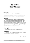
1. Introduction
EX-9044D/9044D-M provides 8 isolated digital output(open collector)
channels and 4 isolated digital input channels. All output channels are
single-ended with common power. (see sec. 1.2.1 Block diagram)
Specifications
Interface : RS-485, 2 wires
Speed : 1200, 2400, 4800, 9600, 19.2K, 38.4K, 57.6K,115.2K
Output channels : 8 isolated output channels with common power
Isolation Voltage: 3750Vrms
Output characteristic: open collector transistor(NPN)
Max output Load voltage: 30 Vdc
Maximum output current sink: 375mA
Input channels : 4 isolated input channels with common source
Input impedance: 3K ohms
Logical level 0 : +1Vdc Max.Logical level 1: +4.0V ~ +30Vdc
LED: 12 digital input/output status LED
Power input : +10V to +30Vdc
Power Consumption : 1.5W
1
1.1 Specifications
EX-9044D
Digital Output
Output Channels
Output Type
Load Voltage
Max Load Current
Isolation Voltage
Digital Input
Input Channels
Logical Level 1
Logical Level 0
Input Impedance
Photo Isolation
Isolation Voltage
Environment
Modbus RTU
Power Requirement
Power Consumption
Operating Temperature
Storage Temperature
EX-9044D-M
8 isolated output channels with common power
Open collector transistor
+30VDC
375mA max
3000VDC
4 isolated input channels with common source
+3.5V to +30V
+1V Max
3K Ohms
3750 Vrms
3000VDC
Not support
Support
+10 to +30 VDC
1.5W
-25°C to +75°C
-30°C to +75°C
Notes:
1. Warm-UP for 30 minutes is recommended!
2
1.2 Wire connection
1.2.1 Block Diagrams
+5V
Led
Display
IN.COM
IN1
EEPROM
IN4
ExtPWR
Single
Controller
Data+
Data+Vs
GND
OutCOM
DO1
RS485
Interface
Power
Supply
DO8
+5V
EX9044D
3
1.2.2 Wiring diagram for the EX-9044D
Dry Contact Input
TTL/CMOS Input
IN.COM
IN.COM
IN1
IN1
IN2
IN2
INx
INx
Digital Output
4
1.3 Default Settings
Default settings for the EX-9044D
modules are as follows:
. Module Address: 01
. DIO Type: 40
. Baud Rate: 9600 bps
Default settings for the EX-9044D-M
modules are as follows:
. Protocol: Modbus RTU
. Module Address: 01
. DIO Type: 40
. Baud Rate: 9600 bps
5
1.4 INIT* Pin Operation
Each EX9000 module has a build-in EEPROM to store
configuration information such as address, type, baudrate
and other information. Sometimes, user may forget the
configuration of the module. Therefore, the EX9000 have a
special mode named "INIT mode" , to help user to resolve
the problem. The "INIT mode" is setting as
Address=00, baudrate=9600bps, no checksum .
To enable INIT mode, please following these steps:
Step1. Power off the module
Step2. Connect the INIT* pin with the GND pin.
Step3. Power on
Step4. Send command $002 (cr) in 9600bps to read the
Configuration stored in the module's EEPROM.
There are commands that require the module to be in INIT
mode. They are:
1. %AANNTTCCFF when changing the Baud Rate and
checksum settings. See Section 2.1 for details.
2. $AAPN, see Section 2.18 for details.
Originally, the INIT mode is accessed by connecting the
INIT* terminal to the GND terminal.
6
1.5 Configuration Tables
Baud Rate Setting (CC)
Code
Baud rate
03
04
05
06
07
08
09
0A
1200
2400
4800
9600
19200
38400
57600
115200
Data Format Setting (FF)
7
6
5
4
*1
*2
3
2
1
0
*3
*1: Counter Update Direction: 0 =Falling Edge,
1=Rising Edge.
*2: Checksum Bit : 0=Disable, 1=Enable.
*3: The reserved bits should be zero.
Read Digital Input/Output Data Format table
Data of $AA6,$AA4,$AALS:(First Data)(Second Data)00
Data of @AA:(First Data)(Second Data)
Note: Both the First Data and the Second Data are in two
hexadecimal digitals format.
Module
EX9044
The First data
DO0~DO7
00~FF
The Second data
DI0~DI3
00~0F
7
2.1 %AANNTTCCFF
Description: Set Module Configuration.
Syntax: %AANNTTCCFF[CHK](cr)
%
AA
a delimiter character
address of setting/response module(00 to FF)
NN
TT
CC
FF
new address for setting/response module(00 to FF)
type 40 for DIO module
new baudrate for setting module.
new data format for setting module.
IF the configuration with new baudrate or new checksum
setting, before using this command, it is needed to short the
INIT* to ground.. The new setting is saved in the EEPROM
and will be effective after the next power-on reset.
Response: Valid Command:
Invalid Command:
!AA
?AA
Example:
Command: %0102240600
Receive: !02
Set module address 01 to 02, return Success.
8
2.2 #**
Description: Synchronized Sampling
Syntax: #**[CHK](cr)
#
delimiter character
**
synchronized sampling command
Response: No response
Example:
Command: #**
No response
Send synchronized sampling command to all modules.
Command: $014
Receive: !10F0000
Read synchronized data from address 01, return S=1, first read
and data is 0F0000
Command: $014
Receive: !00F0000
Read synchronized data from address 01, return S=0, have readed
and data is 0F0000
9
2.3 #AABBDD
Description: Digital Output
Syntax: #AABBDD[CHK](cr)
#
delimiter character
AA
address of reading/response module(00 to FF)
BBDD Output command and parameter
For output multi-channel, the BB=00, 0A or 0B the
select which output group, and the DD is the output
value
Parameter for Multi-Channel Output
Output
Channels
DD for command #AABBDD
BB=00/0A
BB=0B
EX9042D
13
00 to FF DO(0~7) 00 to 1F DO(8~12)
EX9043D
16
00 to FF DO(0~7) 00 to 1F DO(8~15)
EX9044D
8
00 to FF DO(0~7)
NA
NA
EX9050D
8
00 to FF DO(0~7)
NA
NA
EX9055D
8
00 to FF DO(0~7)
NA
NA
EX9060D
4
00 to 0F RL(1~4)
NA
NA
EX9063D
3
00 to 07 RL(1~3)
NA
NA
EX9065D
5
00 to 1F RL(1~5)
NA
NA
EX9066D
7
00 to 7F RL(1~7)
NA
NA
EX9067D
7
00 to 7F RL(1~7)
NA
NA
10
For output single-channel, the BB=1c, Ac or Bc where c is
the selected channel, and the DD must be 00 to clear output
and 01 to set output.
Parameter for Single-Channel Output
Single channel output command #AABBDD
c for BB=1c/Ac
c for BB=Bc
EX9042D
0 to 7
DO(0~7)
0 to 4
DO(8~12)
EX9043D
0 to 7
DO(0~7)
0 to 7
DO(8~15)
EX9044D
0 to 7
DO(0~7)
NA
NA
EX9050D
0 to 7
DO(0~7)
NA
NA
EX9055D
0 to 7
DO(0~7)
NA
NA
EX9060D
0 to 3
RL(1~4)
NA
NA
EX9063D
0 to 2
RL(1~3)
NA
NA
EX9065D
0 to 4
RL(1~5)
NA
NA
EX9066D
0 to 6
RL(1~7)
NA
NA
EX9067D
0 to 6
RL(1~7)
NA
NA
>
Response: Valid Command:
Invalid Command: ?
Ignore Command:
!
Delimiter for ignore the command. The module's
host watchdog timeout status is set, and the output
is set to Safe Value.
11
Example:
Command: #021001
Receive: >
Assume module is EX9044D, set address 02 output channel 0 on,
return success.
Command: #021001
Receive: >
Assume module is EX9044D, set address 02 output channel 0 on,
return ignore, The module’s host watchdog timeout status is set,
and the output is set to Safe Value.
12
2.4 #AAN
Description: Read Digital Input Counter from channel N
Syntax : #AAN[CHK](cr)
#
delimiter character
AA
address of reading/response module (00 to FF)
N
channel to read
Response: Valid Command:
Invalid Command:
>(Data)
?AA
(Data) digital input counter value in decimal, from 00000 to
99999
Example:
Command: #032
Receive: !0300103
Read address 03 digital input counter value of channel 2, return
value 103.
Command: #025
Receive: ?02
Read address 02 digital input counter value of channel 5, return
the channel is not available.
13
2.5 $AA2
Description: Read configuration.
Syntax: $AA2[CHK](cr)
$
delimiter character
AA
address of reading/response module (00 to FF)
2
command for read configuration
Response: Valid Command:
Invalid Command:
TT
CC
FF
!AATTCCFF
?AA
type code of module, it must be 40
baudrate code of module
data format of module
Example:
Command: $012
Receive: !01400600
Read the configuration of module 01, return DIO mode, baudrate
9600, no checksum.
Note: check configuration Tables
14
2.6 $AA4
Description: Reads the synchronized data
Syntax: $AA4[CHK](cr)
$
delimiter character
AA
address of reading/response module (00 to FF)
4
command to read the synchronized data
Response: Valid Command:
Invalid Command:
!S(Data)
?AA
status of synchronized data, 1=first read, 0=been readed
S
(Data) synchronized DIO value. See section 1.5 for data format.
Example:
Command: $014
Receive: ?01
Read address 01 synchronized data, return no data available.
Command: #**
no response
Send synchronized sampling to all modules.
Command: $014
Receive: !100F00
Read address 01 synchronized data, return S=1, first read, and
synchronized data 0F00
15
2.7 $AA5
Description: Read Reset Status
Syntax: $AA5[CHK](cr)
$
delimiter character
AA
address of reading/response module (00 to FF)
5
command for read reset status
Response: Valid Command:
Invalid Command:
S
!AAS
?AA
reset status, 1=the module is been reset, 0=the module is
not been rested
Example:
Command: $ 015
Receive: !011
Read address 01 reset status, return module is been reset
Command: $ 015
Receive: !010
Read address 01 reset status, return no reset occurred.
16
2.8 $AA6
Description: Read Digital I/O Status
Syntax: $AA6[CHK](cr)
$
delimiter character
AA
address of reading/response module (00 to FF)
6
command for read channel status
Response: Valid Command:
Invalid Command:
(Data)
!(Data)
?AA
(First Data)(Second Data)00
Note: Both the First Data and the Second Data are in two
hexadecimal digitals format.
Module
EX9044
The First data
DO0~DO7
00~FF
The Second data
DI0~DI3
00~0F
Example:
Command: $016
Receive: !FF0000
Assume module is EX9044, read address 01 DIO status, return
0F00, digital input channel 0~3 are off, digital output channel
0~7 are on.
17
2.9 $AAF
Description: Read Firmware Version
Syntax: $AAF[CHK](cr)
$
delimiter character
AA
address of reading/response module (00 to FF)
F
command for read firmware version
Response: Valid Command:
Invalid Command:
!AA(Data)
?AA
(Data) Firmware version of module
Example:
Command: $01F
Receive: !01D03.07
Read address 01 firmware version, return version D03.07
18
2.10 $AAM
Description: Read Module Name
Syntax: $AAM[CHK](cr)
$
delimiter character
AA
address of reading/response module (00 to FF)
M
address of reading/response module(00 to FF)
Response: Valid Command:
Invalid Command:
!AA(Data)
?AA
(Data) Name of module
Example:
Command: $01M
Receive: !019044M
Read address 01 module name, return name 9044M
19
2.11 $AAC
Description: Clear Latched Digital Input
Syntax: $AAC[CHK](cr)
$
delimiter character
AA
address of reading/response module (00 to FF)
C
command for clear latched digital input
Response: Valid Command:
Invalid Command:
!AA
?AA
Example:
Command: $01L0
Receive: !01FFFF00
Read address 01 latch-low data, return FFFF.
Command: $01C
Receive: !01
Clear address 01 Latched data, return success.
Command: $01L0
Receive: !000000
Read address 01 latch-low data, return 0000.
20
2.12 $AACN
Description: Clear Digital Input Counter
Syntax: $AACN[CHK](cr)
$
delimiter character
AA
address of reading/response module (00 to FF)
C
command for clear latched digital input
N
digital counter channel N to clear
Response: Valid Command:
Invalid Command:
!AA
?AA
Example:
Command: #010
Receive: !0100123
Read address 01 input channel 0 counter value, return 123.
Command: $01C0
Receive: !01
Clear address 01 input channel 0 counter value, return success.
Command: #010
Receive: !0100000
Read address 01 input channel 0 counter value, return 0.
21
2.13 $AALS
Description: Read Latched Digital Input
Syntax: $AALS[CHK](cr)
$
delimiter character
AA
address of reading/response module (00 to FF)
L
command for read latched digital input
S
1=select latch high status, 0=select latch low status
Response: Valid Command:
Invalid Command:
!(Data)
?AA
(Data) readed status 1=the input channel is latched, 0=the
input channel is not latched.
Example:
Command: $01L1
Receive: !012300
Read address 01 latch-high data, return 0123.
Command: $01C
Receive: !01
Clear address 01 Latched data, return success.
Command: $01L1
Receive: !000000
Read address 01 latch-high data, return 0000.
22
2.14 @AA
Description: Read Digital I/O Status
Syntax: @AA[CHK](cr)
@
delimiter character
AA
address of reading/response module (00 to FF)
Response: Valid Command:
Invalid Command:
(Data)
>(Data)
?AA
(First Data)(Second Data)
Note: Both the First Data and the Second Data are in two
hexadecimal digitals format.
Module
EX9044M
The First data
DO0~DO7
00~FF
The Second data
DI0~DI3
00~0F
Example:
Command: @01
Receive: >FF00
Assume module is EX9044M, read address 01 DIO status, return
0F00, digital input channel 0~3 are off, digital output channel
0~7 are on.
23
2.15 @AA(Data)
Description: Set Digital I/O Status
Syntax: @AA(Data)[CHK](cr)
@
delimiter character
AA
address of reading/response module (00 to FF)
(Data) output value, the data format is following:
(Data) is one character for output channel less than 4
For EX9060D, from 0 to F
For EX9063D, from 0 to 7
(Data) is two characters for output channel less than 8
For EX9044D/50D/55D, from 00 to FF
For EX9065D, from 00 to 1F
For EX9066D/67D, from 00 to 7F
(Data) is four characters for output channel less than 16
For EX9042D, from 0000 to 1FFF
For EX9043D, from 0000 to FFFF
Response: Valid Command:
>
Invalid Command: ?
Ignore Command:
!
!
delimiter for ignore command. The module is in Host
Watchdog Timeout Mode, and the output is set to safe
value.
Example:
Command: @0107 Receive: >
Output address 01 value 7, return success.(The example is
suitable for EX9044M’s digital output channel 0~3 are on)
24
2.16 ~AAO(Data)
Description: Set Module Name
Syntax: ~AAO(Data)[CHK](cr)
~
delimiter character
AA
address of reading/response module (00 to FF)
O
command for set module name
(Data) new name for module, max 6 characters
Response: Valid Command:
Invalid Command:
!AA
?AA
Example:
Command: ~01O9044M
Receive: !01
Set address 01 module name 9044M, return success.
Command: $01M
Receive: !019044M
Read address 01 module name, return name 9044M.
25
2.17 $AAP
Description: Read protocol information of Module
Syntax: $AAP[CHK](cr)
$
delimiter character
AA
address of reading/response module (00 to FF)
P
command for read protocol information of module
Response: Valid Command:
Invalid Command:
S
!AAS
?AA
The protocol supported by the module
10: the protocol set in EEPROM is Normal mode
11: the protocol set in EEPROM is ModbusRTU mode
Example:
Command: $01P
Receive: !0110
Reads the communication protocol of module 01 and returns a
response of 10 meaning the protocol that will be used at the next
power on reset is normal mode.
Command: $01P1
Receive: !01
Sets the communication protocol of module 01 to Modbus RTU
and returns a valid response. And the next power on reset is in
ModbusRTU mode.
26
2.18 $AAPN
Description: Set the protocol information of Module
Syntax: $AAPN[CHK](cr)
$
delimiter character
AA
address of reading/response module (00 to FF)
P
command for set protocol information of module
N
The protocol supported by the module
0: the protocol set in EEPROM is Normal mode
1: the protocol set in EEPROM is ModbusRTU mode
Before using this command, it is needed to short the
INIT* to ground. The new protocol is saved in the
EEPROM and will be effective after the next power-on
reset.
Response: Valid Command:
Invalid Command:
!AA
?AA
Example:
Command: $01P1
Receive: !01
Sets the communication protocol of module 01 to Modbus RTU
and returns a valid response. And the next power on reset is in
ModbusRTU mode.
27
2.19 ~**
Description: Host OK
Host send this command to all modules for send the
information “Host OK”
Syntax: ~**[CHK](cr)
~
delimiter character
**
command for all modules
Response: No response
Example:
Command: ~**
No response
28
2.20 ~AA0
Description: Read Module Status
Syntax: ~AA0[CHK](cr)
~
delimiter character
AA
address of reading/response module (00 to FF)
0
command for read module status
Response: Valid Command:
Invalid Command:
SS
!AASS
?AA
module status, 00=host watchdog timeout status is
clear,04=host watchdog timeout status is set. The status
will store into EEPROM and only may reset by the
command ~AA1.
29
2.21 ~AA1
Description: Reset Module Status
Syntax: ~AA1[CHK](cr)
~
delimiter character
AA
address of reading/response module (00 to FF)
1
command for reset module status
Response: Valid Command:
Invalid Command:
!AA
?AA
30
2.22 ~AA2
Description: Read the Host Watchdog Timeout Value
Syntax: ~AA2[CHK](cr)
~
delimiter character
AA
address of reading/response module (00 to FF)
2
command for read host watchdog timeout value
Response: Valid Command:
Invalid Command:
E
VV
!AAEVV
?AA
host watchdog enable status, 1=Enable, 0=Disable
timeout value in HEX format, each count is 0.1 second
01=0.1 second and FF=25.5 seconds
31
2.23 ~AA3EVV
Description: Set host Watchdog Timeout Value
Syntax: ~AA3EVV[CHK](cr)
~
delimiter character
AA
address of reading/response module (00 to FF)
3
command for set host watchdog timeout value
E
1=Enabled / 0=Disable host watchdog
VV
timeout value, from 01 to FF, each for 0.1 second
Response: Valid Command:
Invalid Command:
!AA
?AA
Example:
Command: ~010
Receive: !0100
Read address 01 modules status, return host watchdog timeout
status is clear.
Command: ~013164
Receive: !01
Set address 01 host watchdog timeout value 10.0 seconds and
enable host watchdog, return success.
Command: ~012
Receive: !01164
Read address 01 host watchdog timeout value, return that host
watchdog is enabled, and time interval is 10.0 seconds.
Command: ~**
No response
32
Reset the host watchdog timer. Wait for about 10 seconds and
don't send command~**, the LED of module will go to flash.
The flash LED indicates the host watchdog timeout status is set.
Command: ~010
Receive: !0104
Read address 01 module status, return host watchdog timeout
status is set.
Command: ~012
Receive: !01064
Read address 01 host watchdog timeout value, return that host
watchdog is disabled, and time interval is 10.0 seconds.
Command: ~011
Receive: !01
Reset address 01 host watchdog timeout status, return success
And the LED of this module stop flash.
Command: ~010
Receive: !0100
Read address 01 module status, return host watchdog timeout
status is clear.
33
2.24 ~AA4V
Description: Read Power On/Safe Value
Syntax: ~AA4V[CHK](cr)
~
delimiter character
AA
address of reading/response module (00 to FF)
4
command for read Power On/Safe value
V
P= read Power On Value, S= read Safe Value
Response: Valid Command:
Invalid Command:
!AA(Data)
?AA
(Data) Power On Value or Safe Value
For EX9042D/43D(Data) is VVVV,
where VVVV is the Power On Value (or Safe Value).
For other modules, (Data) is VV00,
where VV is the Power On Value(or Safe Value).
Example:
Command: @0100 Receive: >
Output address 01 Value 00, return success.
Command: ~015S Receive: !01
Set address 01 Safe Value, return success.
Command: @01FF Receive: >
Output address 01 Value FF, return success..
Command: ~015P Receive: !01
Set address 01 Power On Value, return success.
34
Command: ~014S Receive: !0100
Read address 01 Safe Value, return 00.
Command: ~014P Receive: !01FF
Read address 01 Power On Value, return FF.
35
2.25 ~AA5V
Description: Set Power On/Safe Value
Syntax: ~AA5V[CHK](cr)
~
delimiter character
AA
address of reading/response module (00 to FF)
5
command for set Power On/Safe value
V
P= set current output as Power On Value, S= set current
output as Safe Value
Response: Valid Command:
Invalid Command:
!AA
?AA
Example:
Command: @01AA Receive: >
Output address 01 Value AA, return success.
Command: ~015P Receive: !01
Set address 01 Power On Value, return success.
Command: @0155 Receive: >
Output address 01 Value 55, return success.
Command: @015S Receive: !01
Set address 01 Safe Value, return success..
Command: ~014P Receive: !01AA00
Read address 01 Power On Value, return AA.
Command: ~014S Receive: !015500
Read address 01 Safe Value, return 55.
36
EX9044-M Quick Start
1. The default setting is MODBUS mode after Power On.
2. Using INIT pin to contact with GND pin then Power On will enter
Normal mode.
3. Command: $00P0 is set EX9044-M to Normal mode after Repower On.
On normal mode, user can set other setting like address, Baudrate, …..
(Please check the EX9000 user manual).
4. Command: $AAP1 is set to MODBUS mode after Repower On.
5. Under Normal mode that Command: $AAP can check which mode it is
after Repower On.
Response:
!AA10=Normal
!AA11=MODBUS
The Modbus protocol was originally developed for Modicon controllers
by Modicon Inc. Detailed information can be found at
http://www.modicon.com/techpubs/toc7.html. Visit
http://www.modbus.orq to find more valuable information.
9000M series modules support the Modbus RTU protocol. The
communication Baud Rates range from 1200bps to 115200bps. The parity,
data bits and stop bits are fixed as no parity, 8 data bits and 1stop bit.
The following Modbus functions are supported.
37
01(0x01) Read Digital Input/Output Value
Request
00
Address
01
Function code
02~03 Starting channel
1 Byte 1-247
1 Byte 0x01
2 Bytes 0x0000~0x0007 for DO readback value
0x0020~0x0023 for DI readback value
0x0040~0x0043 for DI Latch high value
0x0060~0x0063 for DI Latch low value
0x0080~0x0087 for DO safe value
0x00A0~0x00A7 for DO power-on value
04~05 Input/Output
2 Bytes Input: 0x0001~0x0004
channel numbers
Output: 0x0001~0x0008
Response
00
Address
01
Function code
02
Byte count
03
Input/Output
channel readback
value
Error Response
00
Address
01
Function code
02
Exception code
1 Byte
1 Byte
1 Byte
1 Byte
1-247
0x01
1
0x00~0x0F
A bit corresponds to a channel. When the
bit is 1 it denotes that the value of the
channel that was set is ON. if the bit is 0 it
denotes that the value of the channel that
was set is OFF.
1 Byte
1 Byte
1 Byte
1-247
0x81
Refer to the Modbus standard for more
details.
38
02(0x02) Read Digital Input Value
Request
00
Address
01
Function code
02~03 Starting channel
04~05 Input channel
numbers
1 Byte
1 Byte
2 Bytes
2 Bytes
1-247
0x02
0x0000~0x0003
0x0001~0x0004
Response
00
Address
01
Function code
02
Byte count
03
Input channel
readback value
1 Byte
1 Byte
1 Byte
1 Byte
1-247
0x02
1
0x00~0x0F
A bit corresponds to a channel. When the
bit is 1 it denotes that the value of the
channel that was Input response. if the bit
is 0 it denotes that the value of the channel
that was no Input response .
1 Byte
1 Byte
1 Byte
1-247
0x82
Refer to the Modbus standard for more
details.
Error Response
00
Address
01
Function code
02
Exception code
39
03(0x03) Read Digital Input Count Value
Request
00
Address
01
Function code
02~03 Starting channel
04~05 Input channel
numbers
1 Byte
1 Byte
2 Bytes
2 Bytes
1-247
0x03
0x0000~0x0003
0x0001~0x0004
Response
00
Address
1 Byte 1-247
01
Function code
1 Byte 0x03
02
Byte count
1 Byte N* x 2
03~ Input channel
N* x 2 Each channel can record a maximum
count value
Byte
count value up to 65535(0xFFFF).
N*=Number of input channels
Error Response
00
Address
01
Function code
02
Exception code
1 Byte
1 Byte
1 Byte
1-247
0x83
Refer to the Modbus standard for more
details.
40
04(0x04) Read Digital Input Count Value
Request
00
Address
01
Function code
02~03 Starting channel
04~05 Input channel
numbers
1 Byte
1 Byte
2 Bytes
2 Bytes
1-247
0x04
0x0000~0x0003
0x0001~0x0004
Response
00
Address
1 Byte 1-247
01
Function code
1 Byte 0x04
02
Byte count
1 Byte N* x 2
03~ Input channel
N* x 2 Each channel can record a maximum
count value
Byte
count value up to 65535(0xFFFF).
N*=Number of input channels
Error Response
00
Address
01
Function code
02
Exception code
1 Byte
1 Byte
1 Byte
1-247
0x84
Refer to the Modbus standard for more
details.
41
05(0x05) Write Digital Output/Clear DI count Value
(Single channel)
Request
00
Address
01
Function code
02~03 Output channel
number
04~05 Output value
Response
00
Address
01
Function code
02~03 Output channel
numbers
04~05 Output value
Error Response
00
Address
01
Function code
02
Exception code
1 Byte 1-247
1 Byte 0x05
2 Bytes 0x0000~0x0007 for output channel
0x0107 to clear the latch value
0x0200~0x0203 to clear the DI counter
value
2 Bytes A value of 0xFF00 sets the output to ON.
A value of 0x0000 set it to OFF. All other
values are illegal and won’t affect the coil.
1 Byte 1-247
1 Byte 0x05
2 Bytes The value is the same as byte 02 and
03 of the Request
2 Bytes The value is the same as byte 04 and
05 of the Request
1 Byte
1 Byte
1 Byte
1-247
0x85
Refer to the Modbus standard for more
details.
42
15(0x0F) Write Digital Output/Clear DI count Value
(Multi channel)
Request
00
Address
01
Function code
02~03 Starting channel
1 Byte 1-247
1 Byte 0x0F
2 Bytes 0x0000~0x0007 for output channel
0x0200~0x0203 to clear the DI counter
value
0x0080~0x0087 for Safe value
0x00A0~0x00A7 for Power-on value
04~05 Input/Output
2 Bytes Input: 0x0001~0x0004
channel numbers
Output: 0x0001~0x0008
06
Byte count
1 Byte 1
07
Output
1 Byte 0x00~0xFF
A bit corresponds to a channel. When the bit is
value/Clear DI
1 it denotes that the value of the channel that
count value
was set is ON. if the bit is 0 it denotes that the
value of the channel that was set is OFF.
Response
00
Address
01
Function code
02~03 Starting channel
04~05 Output channel
numbers
1 Byte 1-247
1 Byte 0x0F
2 Bytes The value is the same as byte 02 and
03 of the Request
2 Bytes The value is the same as byte 04 and
05 of the Request
Error Response
00
Address
01
Function code
02
Exception code
1 Byte
1 Byte
1 Byte
1-247
0x8F
Refer to the Modbus standard for more
details.
43
01(0x01) Read WDT timeout status
Request
00
Address
01
Function code
02~03 Starting channel
04~05 Output channel
numbers
1 Byte
1 Byte
2 Bytes
2 Bytes
1-247
0x01
0x010D
0x0001
Response
00
Address
01
Function code
02
Byte count
03
Output channel
readback value
1 Byte
1 Byte
1 Byte
1 Byte
1-247
0x01
1
0x00 The WDT timeout status is clear
0x01 The WDT timeout status is enable
Error Response
00
Address
01
Function code
02
Exception code
1 Byte 1-247
1 Byte 0x81
1 Byte Refer to the Modbus standard for more
details.
44
03(0x03) Read WDT timeout Value
Request
00
Address
01
Function code
02~03 Starting channel
04~05 Input channel
numbers
1 Byte
1 Byte
2 Bytes
2 Bytes
1-247
0x03
0x01E8
0x0001
Response
00
Address
01
Function code
02
Byte count
03~ Input channel count
value
1 Byte
1 Byte
1 Byte
1 Byte
1-247
0x03
2
0x0000~0x00FF WDT timeout
value, 0~255, in 0.1 second
Error Response
00
Address
01
Function code
02
Exception code
1 Byte 1-247
1 Byte 0x83
1 Byte Refer to the Modbus standard for
more details.
45
03(0x03) Send Host OK
Request
00
Address
01
Function code
02~03 Starting channel
04~05 Input channel numbers
1 Byte
1 Byte
2 Bytes
2 Bytes
1-247
0x03
0x3038
0x0000
No Response
04(0x04) Send Host OK
Request
00
Address
01
Function code
02~03 Starting channel
04~05 Input channel numbers
1 Byte
1 Byte
2 Bytes
2 Bytes
1-247
0x04
0x3038
0x0000
No Response
46
05(0x05) Set WDT timeout /Clear WDT timeout status
Request
00
Address
01
Function code
02~03 Output channel
number
04~05 Output value
Response
00
Address
01
Function code
02~03 Output channel
numbers
04~05 Output value
Error Response
00
Address
01
Function code
02
Exception code
1 Byte 1-247
1 Byte 0x05
2 Bytes 0x0104 Set WDT timeout
enable/disable
0x010D Clear WDT timeout status
2 Bytes 0xFF00 for WDT timeout enable
0x0000 for WDT timeout disable
0xFF00 for Clear WDT timeout
status
1 Byte 1-247
1 Byte 0x05
2 Bytes The value is the same as byte 02 and
03 of the Request
2 Bytes The value is the same as byte 04 and
05 of the Request
1 Byte 1-247
1 Byte 0x85
1 Byte Refer to the Modbus standard for
more details.
47
06(0x06) Set WDT timeout Value
Request
00
Address
01
Function code
02~03 Starting channel
04~05 Input channel
numbers
Response
00
Address
01
Function code
02~03 Output channel
numbers
04~05 Output value
Error Response
00
Address
01
Function code
02
Exception code
1 Byte
1 Byte
2 Bytes
2 Bytes
1-247
0x06
0x01E8
0x0000~0x00FF WDT timeout
value, 0~255, in 0.1 second
1 Byte 1-247
1 Byte 0x06
2 Bytes The value is the same as byte 02 and
03 of the Request
2 Bytes The value is the same as byte 04 and
05 of the Request
1 Byte 1-247
1 Byte 0x86
1 Byte Refer to the Modbus standard for
more details.
48
Modbus Mapping Table:
EX9044M (DI*4, DO*8)
ADDR
00033~00036
Item
Digital Input channel for DI0~3
Attribute
R
00065~00068
00097~00100
00264
DI Latch high value for DI0~3
DI Latch low value for DI0~3
Clear the Latch value
R
R
W
30001~30004
00513~00516
Digital input counter for DI0~3
Clear the DI counter value for DI0~3
R
W
00001~00008
Digital output channel for DO0~7
R/W
49