1
9.
Starting approximately 1/2” from the top center of the REAR CONSOLE, Create a 1/2” wide by 3/8” deep notch in
the REAR CONSOLE top.
10.
Locate the REMOTE CONTROL. Remove the two HORIZONTAL CABLE
TIES (H) for a VERTICAL (V) installation. Secure the REMOTE CONTROL to the left end of the ERGO CROSSBAR as shown. Be sure the
CABLE TIES are pulled tight and trim the excess CABLE TIES.
11.
Route the REMOTE CONTROL CABLE along the LEFT HANDLEBAR.
Secure the REMOTE CONTROL CABLE using two CABLE TIES in the
locations shown. Be sure the CABLE TIES are pulled tight and trim the
excess CABLE TIES. Route the remaining REMOTE CONTROL CABLE
along the handlebar and up through the DISPLAY CONSOLE ACCESS
PANEL.
12.
With the POWER CORD, COAXIAL CABLE and REMOTE CONTROL
CORD oriented in the TOP CONSOLE NOTCH as shown, replace the
CONSOLE CONNECTORS and secure the FRONT CONSOLE using the
eight previously removed SCREWS. Tighten the SCREWS securely.
13.
Replace the ACCESSORY TRAYS. Be sure the trays snap securely into position.
14.
Replace and secure the MOTOR COVER using the four previously removed SCREWS. Tighten the SCREWS
securely.
15.
Replace the LEFT LOWER HANDLEBAR ENDCAP. Be sure the trays snap securely into position.
16.
Remove the LEFT and RIGHT UPPER HANDLEBAR ENDCAPS and discard them.
17.
Position the BRACKET TUBE (B) as shown and slide the ends into the HANDRAILS (C) until fully seated.
18.
Install the four SET SCREWS (D) into the
BRACKET TUBE MOUNTING ARMS and
tighten the SET SCREWS securely.
19.
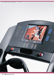
Attach the ENTERTAINMENT CONSOLE
(E) to the UPPER MOUNTING PLATE (F)
using four SCREWS (G). Tighten the
SCREWS to 6-8 in-lbs. Do not overtighten
the SCREWS.
20.
Connect the COAXIAL CABLE and POWER
CABLE to the rear of the ENTERTAINMENT
CONSOLE (E) as shown under Console
Cable Connections at the end of this section.
19