1
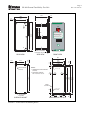
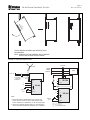
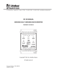
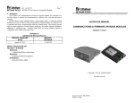
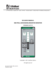
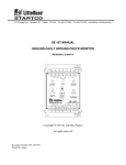
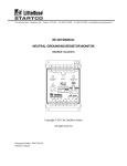
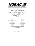
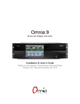
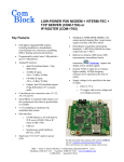
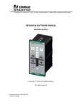
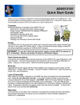
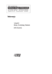
3714 Kinnear Place Saskatoon, SK Canada S7P 0A6 Ph: (306) 373-5505 Fx: (306) 374-2245 www.littelfuse.com/relayscontrols SE-400 MANUAL GROUND-FAULT-RELAY TEST UNIT Revision 1-A-072115 LITTELFUSE STARTCO GROUND-FAULT-RELAY TEST UNIT SE-400 AMPERES THERMAL LIMIT USE SWITCHES LABELLED AMPERES TO SET MAGNITUDE (0.5 TO 9.9 A) OF OUTPUT CURRENT. USE SWITCHES LABELLED SECONDS TO SET DURATION (0.1 TO 9.9 s) OF OUTPUT CURRENT. PRESS TEST TO INITIATE OUTPUT CURRENT. DISPLAY INDICATES MAGNITUDE OF OUTPUT CURRENT FOR DURATION OF OUTPUT. SET SWITCHES LABELLED SECONDS TO 0.0 FOR MANUAL CONTROL OF OUTPUT DURATION. PUSH TEST TO SWITCH OUTPUT ON OR OFF. AMPERES 2 SECONDS 4 3 0.5 TO 9.9 0 0.1 TO 9.9 TEST Copyright © 2015 by Littelfuse Startco All rights reserved. Document Number: PM-1605-EN Printed in Canada. SE-400 Ground-Fault-Relay Test Unit This page intentionally left blank. Page i Rev. 1-A-072115 SE-400 Ground-Fault-Relay Test Unit TABLE OF CONTENTS SECTION PAGE 1 2 General ................................................................. 1 Operation ............................................................. 1 2.1 Front-Panel Controls ............................................. 1 2.1.1 Amperes ..................................................... 1 2.1.2 Seconds ...................................................... 1 2.1.3 Test ............................................................ 1 2.2 Indication .............................................................. 1 2.3 Thermal Limit ....................................................... 1 3 Installation ........................................................... 1 4 Test Procedure .................................................... 1 5 Troubleshooting .................................................. 1 6 Technical Specifications...................................... 4 7 Ordering Information ......................................... 4 8 Warranty ............................................................. 4 Appendix A SE-400 Revision History ........................... 5 LIST OF FIGURES FIGURE 1 2 3 PAGE SE-400 Outline and Mounting Details .................. 2 Panel-Mounting Procedure.................................... 3 Typical Connection Diagrams............................... 3 DISCLAIMER Specifications are subject to change without notice. Littelfuse Startco is not liable for contingent or consequential damages, or for expenses sustained as a result of a malfunction, incorrect application, or incorrect adjustment. Page ii Rev. 1-A-072115 SE-400 Ground-Fault-Relay Test Unit This page intentionally left blank. Page iii Rev. 1-A-072115 Page 1 Rev. 1-A-072115 SE-400 Ground-Fault-Relay Test Unit 1. GENERAL 3. INSTALLATION The SE-400 is an ac current source with a programmable output. The magnitude and duration of the output can be selected with front-panel switches so that ground-fault-relay coordination can be confirmed at the push of a button. The current output is transformer isolated from supply voltage. SE-400 outline and mounting details are shown in Fig. 1. Panel-mounting procedures are shown in Fig. 2. Connect L1 and L2 to supply voltage using L2 as N. Connect ground terminal 1 ( ) to ground. Loop an output conductor through the windows of the groundfault CT's connected to the ground-fault relays under test. Connect one end of the output conductor to terminal 1 (OP1) and the other end to terminal 12 (OP2). For output-conductor lengths under 40 ft, use 14 gauge wire. For output-conductor lengths over 40 ft and up to 80 ft, use 12 gauge wire. If remote operation is required, connect a normally open momentary contact to terminals 8 and 9 (RMT1 and RMT2). Low-level contacts are recommended. Typical connection diagrams are shown in Fig. 3. 2. OPERATION 2.1 FRONT-PANEL CONTROLS 2.1.1 AMPERES The AMPERES switch has four push buttons and a two-digit numeric indicator to adjust current output to the desired value. The range is 0.5 to 9.9 A. If a value below 0.5 is selected, there will be no output. 2.1.2 SECONDS The SECONDS switch has four push buttons and a two-digit numeric indicator to adjust output duration. The range is 0.1 to 9.9 s, or select 0.0 for continuousoutput operation. 2.1.3 TEST Press TEST for an output burst of the magnitude and duration selected by AMPERES and SECONDS. Press TEST again to stop a continuous-output operation. 2.2 INDICATION The two-digit LED display indicates the magnitude of the output current for the duration of the output burst. The centre decimal point serves as a supply voltage indicator. A decimal point on the right side of the display is used to indicate a thermal-limit condition. 2.3 THERMAL LIMIT When the SE-400 is used in the continuous-output mode, the internal circuit temperature can reach the thermal-limit temperature. To prevent damage to the SE-400, the current output is disabled and the thermallimit indicator turns on. The output remains disabled until the temperature has fallen to a safe level, at which time the thermal-limit indicator turns off and the output is enabled. 4. TEST PROCEDURE Set the required output current level0.5 to 9.9 A. The recommended test current is 120% of the groundfault trip level of the device being tested. Set the output duration0.1 to 9.9 s or 0.0 for push-on push-off operation. Press the TEST button. The ground-fault unit(s) being tested should trip. 5. TROUBLESHOOTING Problem: No current output when the TEST button is pressed. Possible Causes: Loose output connections. Resistance of the output wire is too high. VA requirement of the load is too high. Current is set to less than 0.5 A. No supply voltage. Thermal limit exceeded. Power-supply fuse F1 open. Troubleshooting: Check the SE-400 operation by connecting a short length of wire across the output terminals and pressing the TEST button. If using a remote test switch, check remote switch operation and connection to the SE-400. Page 2 Rev. 1-A-072115 SE-400 Ground-Fault-Relay Test Unit 3.4 (0.13) 3.2 (0.12) 139.7 (5.50) 104.0 (4.09) 91.7 (3.61) LITTELFUSE STARTCO GROUND-FAULT-RELAY TEST UNIT SE-400 1 2 3 4 5 6 7 8 9 10 11 12 212.7 (8.37) 218.4 (8.60) F1 AMPERES L1 L2 THERMAL LIMIT USE SWITCHES LABELLED AMPERES TO SET MAGNITUDE (0.5 TO 9.9 A) OF OUTPUT CURRENT. R MT 1 R MT 2 OP 1 OP2 USE SWITCHES LABELLED SECONDS TO SET DURATION (0.1 TO 9.9 s) OF OUTPUT CURRENT. PRESS TEST TO INITIATE OUTPUT CURRENT. DISPLAY INDICATES MAGNITUDE OF OUTPUT CURRENT FOR DURATION OF OUTPUT. SET SWITCHES LABELLED SECONDS TO 0.0 FOR MANUAL CONTROL OF OUTPUT DURATION. PUSH TEST TO SWITCH OUTPUT ON OR OFF. AMPERES 2 SECONDS 4 3 0.5 TO 9.9 0 0.1 TO 9.9 TEST PANEL THICKNESS 1.6 (0.06) TO 4.8 (0.19) NOTES: M4 OR 8-32 TAP (NOTE 2) 6.4 R=2. 2 (0.09) 1. DIMENSIONS IN MILLIMETRES (INCHES). 2.5 (0.10) 2.5 (0.10) 2.5 (0.10) 195.0 (7.68) 200.0 (7.87) 212.7 (8.37) 203.2 (8.00) 2. MOUNTING SCREWS: M4 x 10 OR 8-32 x 0.375. (0.25) 98.4 (3.87) 93.3 (3.67) 76.2 (3.00) 2.5 (0.10) 63.5 (2.50) 5.0 (0.20) 14.1 (0.56) FRONT VIEW SIDE VIEW REAR VIEW REAR PANEL OUTLINE SURFACE MOUNT FIGURE 1. SE-400 Outline and Mounting Details. R=4. 8 (0.19) MAXIMUM 8.2 (0.32) 8.2 (0.32) PANEL-MOUNT CUTOUT 6.4 (0.25) 2.5 (0.10) BEZEL OUTLINE Page 3 Rev. 1-A-072115 SE-400 Ground-Fault-Relay Test Unit STEP 1 STEP 2 1 STEP 3 1 2 3 4 5 6 7 8 9 10 11 12 2 L1 3 4 L2 5 6 T1 7 R MM T 2 8 R 9 1 1 0 1 O PP 2 1 2 O 1 1 2 3 4 5 6 7 8 9 10 11 12 L1 L2 R MT 1 R MT 2 OP 1 OP2 L1 L2 R MT 1 R MT 2 OP 1 OP2 THE SE-400 MAY BE PANEL MOUNTED WITHOUT DISASSEMBLY. NOTE: REMOVE PLUG-IN TERMINAL BLOCK BEFORE INSTALLING SE-400 THROUGH PANEL. FIGURE 2. Panel-Mounting Procedure. SE-CS30 NEUTRAL FROM POWER SOURCE LOAD TO SE-330 4 NGR L N 11 3 5 OP1 REMOTE TEST 9 12 R1 L L1 L2 1 8 OP2 N ITEST TO SENSING RESISTOR TERMINAL N SE-400 11 10 L RMT2 S1 S2 L1 L2/N N 3 5 OP1 1. FOR DEVICES WITH LOWER TRIP LEVELS SUCH AS THE SE-704 USE THE CIRCUIT AT RIGHT. RESISTORS R1 AND R2 WILL LOWER TEST CURRENT TO 10% OF SE-400 SETTING. 2. FOR A TEST CURRENT HIGHER THAN 9.9 A, USE MULTIPLE OUTPUT-CONDUCTOR WRAPS THROUGH THE CT WINDOW. FIGURE 3. Typical Connection Diagrams. REMOTE TEST 8 9 OP2 L1 L2 1 NOTE: SE-704 R2 11 RMT1 5 SE-400 RMT1 RMT2 R1 = 1 Ω, 10 W, 1% R2 = 0.1 Ω, 10 W, 1% ITEST = 1/10 SE-400 SETTING 12 Page 4 Rev. 1-A-072115 SE-400 Ground-Fault-Relay Test Unit 6. TECHNICAL SPECIFICATIONS Supply : 120 Vac ............................... 80 VA, 120 Vac, (+12, -30%), 50/60 Hz 240 Vac ............................... 80 VA, 240 Vac, (+12, -30%), 50/60 Hz Fuse Rating (F1) ....................... 1 A, 250 Vac Fuse Part Number ..................... Littelfuse 313.001 or Bussman AGC1 Output: Current Setting .................... 0.5 to 9.9 A, 0.1-A increments Duration Setting .................. 0.1 to 9.9 s, 0.1-s increments or continuous Maximum Burden ............... 0.13 ohms Voltage ............................... 5.0 Vac maximum Duty Cycle at 25°C (77°F): 12 VA............................... Continuous 34 VA Maximum ............. 15 minutes ON 30 minutes OFF Accuracy ............................. ± 3% PWB Conformal Coating ......... MIL-1-46058 qualified, UL QMJU2 recognized Dimensions: Height ................................. 212.7 mm (8.4”) Width .................................. 104.0 mm (4.1”) Depth .................................. 142.9 mm (5.6”) Shipping Weight ....................... 2.2 kg (4.8 lb) Environment: Operating Temperature ....... -40 to 60C (-40 to 140°F) Storage Temperature........... -55 to 80C (-67 to 160°F) 7. ORDERING INFORMATION SE-400- BLANK – 120-Vac Supply 02 – 240-Vac Supply SE-410 ......................................... Selector Switch SE-400IRC .................................. Impact Resistant Case 8. WARRANTY The SE-400 Ground-Fault-Relay Test Unit is warranted to be free from defects in material and workmanship for a period of five years from the date of purchase. Littelfuse Startco will (at Littelfuse Startco’s option) repair, replace, or refund the original purchase price of an SE-400 that is determined by Littelfuse Startco to be defective if it is returned to the factory, freight prepaid, within the warranty period. This warranty does not apply to repairs required as a result of misuse, negligence, an accident, improper installation, tampering, or insufficient care. Littelfuse Startco does not warrant products repaired or modified by non-Littelfuse Startco personnel. Page 5 Rev. 1-A-072115 SE-400 Ground-Fault-Relay Test Unit MANUAL RELEASE DATE July 21, 2015 APPENDIX A SE-400 REVISION HISTORY MANUAL PRODUCT REVISION REVISION (REVISION NUMBER ON PRODUCT LABEL) 1-A-072115 MANUAL REVISION HISTORY REVISION 1-A-072115 SECTION 5 Fig. 3 updated. SECTION 6 Voltage and accuracy specifications added. APPENDIX A Revision history added. PRODUCT REVISION HISTORY PRODUCT REVISION 05B Current release. 05B SE-400 Ground-Fault-Relay Test Unit This page intentionally left blank. Page 6 Rev. 1-A-072115