1
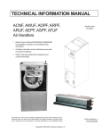
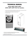
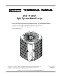
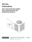
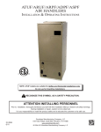
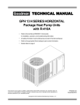
TECHNICAL MANU
AL
MANUAL
MBR Blowers
• Refer to Service Manual RS6100004 for installation, operation, and troubleshooting information.
• All safety information must be followed as provided in the Service Manual.
• Refer to the appropriate Parts Catalog for part number information.
• Models listed on page 2.
This manual is to be used by qualified, professionally trained HVAC technicians only. The
manufacturer does not assume any responsibility for property damage or personal injury due
to improper service procedures or services performed by an unqualified person.
Copyright © 2013 Goodman Manufacturing Company, L.P.
RT6223004
October 2013
PRODUCT IDENTIFICATION
The model number is used for positive identification of component parts used in manufacturing. Please use this number
when requesting service or parts information.
MB
R
08
DESIGN SERIES
MB: Modular Blower
00
A
FACTORY HEAT
00: No Heat
MOTOR TYPE
R: Constant Speed
A
DESIGN SERIES
A: First Series
CIRCUIT
BREAKER
A: No Circuit Breaker
B: Circuit Breaker
AIRFLOW
DELIVERED
08: 800 CFM
12: 1200 CFM
16: 1400 CFM
20: 2000 CFM
1
ELECTRICAL
SUPPLY
1: 208-230v/60 Hertz
Single Phase
MBR0800
MBR1200
MBR1600
MBR2000
WARNING
HIGH VOLTAGE!
Disconnect ALL power before servicing or installing this unit. Multiple power
sources may be present. Failure to do so may cause property damage, personal
injury or death.
The manufacturer will not be responsible for any injury or property damage arising from improper service or service
procedures. If you install or perform service on this unit,
you assume responsibility for any personal injury or
property damage which may result. Many jurisdictions
require a license to install or service heating and air
conditioning equipment.
WARNING
2
Installation and repair of this unit
should be performed ONLY by
individuals meeting the requirements of an "entry level
technician" as specified by the Air-Conditioning, Heating,
and Refrigeration Institute (AHRI). Attempting to install
or repair this unit without such background may result
in product damage, personal injury or death.
WARNING
PRODUCT DESIGN
The MBR Blower Cabinets are used in combination with a
cased evaporator coil. This combination of blower and coil
functions as the indoor part of a split air-conditioning system, and may be matched with a remote condensing or heat
pump unit. The blower cabinet can also function as an electric furnace when used with an electric heater.
NOTE: The electric heating elements for electric furnace
installation are not shipped with the cabinet and are fieldinstalled.
Systems should be properly sized by heat gain and loss
calculations made according to methods of the Air Conditioning Contractors Association (ACCA) or equivalent. It is
the contractor’s responsibility to ensure the system has adequate capacity to heat or cool the conditioned space.
CLEARANCES AND ACCESSIBILITY
The unit can be positioned for upflow, counterflow, horizontal
right or horizontal left operation. Zero clearance is allowed
on all sides for combustible materials. Thirty-six inches should
be allotted on the door side for maintenance and service.
WARNING
INSULATION
To ensure efficient operation, review the following precautions.
•
If the unit is located in an area with high ambient temperature and/or high humidity, the air handler may be
subject to nuisance sweating of the casing. On these
installations, a wrap of 2” fiberglass insulation with a
vapor barrier is recommended.
•
The factory recommends insulating the duct running
through any unconditioned spaces.
To reduce operating sound and vibration transmission use
flexible canvas duct connections at the cabinet.
The United States Environmental Protection Agency (“EPA”) has issued various regulations regarding the introduction and disposal of refrigerants introduced into this unit. Failure to follow
these regulations may harm the environment and can lead to the imposition of substantial fines.
These regulations may vary by jurisdiction. Should questions arise, contact your local EPA office.
Do not connect or use any device
that is not design certified by the
manufacturer for use with this unit.
Serious property damage, personal injury, reduced unit
performance and/or hazardous conditions may result
from the use of such non-approved devices.
WARNING
To reduce risk of rusting, do not install the unit blower directly on the ground or on a floor that is likely to be wet. In
such environments, the unit must be elevated by use of a
sturdy, nonporous material.
To prevent the risk of property
damage, personal injury, or death,
do not store combustible materials or use gasoline or
other flammable liquids or vapors in the vicinity of this
appliance.
WARNING
3
BLOWER SPECIFICATIONS
D
3 1/4
5 C1/8
(3) KNOCKOUTS
1.125
1.375
1.750
.875 KNOCKOUT
(2 PLACES)
H
5
6 1/2
W
MBR800/1200/1600/2000
Dimensions, inches (mm) Shipping
Physical Information
MODEL
1
Blower Wheel Blower Motor
(D x W)
(HP)
MCA1
MOP1
W
H
D
Weight
lbs.(kg)
17½
(445)
26
(660)
21
(533)
72
(32.6)
MBR800
9X6
1/4
1.9
15
MBR1200
9x8
1/3
3.0
15
MBR1600
10x8
1/3
3.8
15
21
(533)
30
(762)
21
(533)
82
(37.2)
MBR2000
10x10
1/2
4.9
15
24½
(622)
30
(762)
21
(533)
94
(42.6)
Minimum Circuit Ampacity (MCA) and Maximum Overcurrent Protection (MOP) for blower without supplemental heat
installed. Refer to unit nameplate for MCA and MOP with approved accessory heaters installed.
4
16.500
SMALL
10.159
8.840
20.021
MBR800/1200/1600/2000
MEDIUM
11.209
11.029
BLOWER OPENING DIMENSIONS
(TOP VIEW)
11.209
LARGE
23.464
13.178
BLOWER SPECIFICATIONS
5
BLOWER SPECIFICATIONS
HKR HEATER DATA
ELECTRIC HEATER KIT
BLOWER
NO HEAT KIT
HKR-03*
HKR05-(C)'
HKR-06*
HKR-08(C)* HKR-10(C)*
0800AA-1AA
X
X
X
X
X
X
1200AA-1AA
X
X
X
X
X
X
1600AA-1AA
X
X
X
X
X
X
2000AA-1AA
X
X
X
X
X
X
MBR
^ = Circuit 1: Single Phase for Air Handler Motor
Circuit 2: 3-Phase for HKR3 Heater Kits
* = Revision level that my or may not be designated
C = Circuit Breaker option
X = Allowable combinations
~ = Restricted combinations
ELECTRIC HEATER KIT
BLOWER
HKR-15C*
HKR-20C*
HKR-21C*
^HKR3-15*
^HKR3-20*
0800AA-1AA
~
~
~
~
~
1200AA-1AA
X
X
X
X
X
1600AA-1AA
X
X
X
X
X
2000AA-1AA
X
X
X
X
X
MBR
^ = Circuit 1: Single Phase for Air Handler Motor
Circuit 2: 3-Phase for HKR3 Heater Kits
* = Revision level that my or may not be designated
C = Circuit Breaker option
X = Allowable combinations
~ = Restricted combinations
BLOWER PERFORMANCE DATA
SPEED
HIGH
MEDIUM
LOW
STATIC
MBR0800**-*
SCFM
MBR1200**-*
SCFM
MBR1600**-*
SCFM
MBR2000**-*
SCFM
0.1
1240
1500
1800
2160
0.2
1170
1460
1740
2080
0.3
1120
1360
1680
1990
0.4
1060
1280
1610
1890
0.5
980
1200
1520
1790
0.6
900
1110
1430
1690
0.1
900
1380
1540
1730
0.2
850
1320
1490
1670
0.3
790
1270
1450
1590
0.4
740
1200
1400
1520
0.5
680
1140
1350
1420
0.6
605
1040
1280
1320
0.1
650
1170
1130
1520
0.2
590
1130
1100
1450
0.3
540
1080
1070
1360
0.4
500
1020
1030
1290
0.5
430
950
990
1200
0.6
330
830
930
1090
External static is for blower @ 230 volts, it does not include coil, air filter or electric heaters.
WIRING DIAGRAMS
HIGH VOLTAGE!
DISCONNECT ALL POWER BEFORE SERVICING OR INSTALLING THIS
UNIT. MULTIPLE POWER SOURCES MAY BE PRESENT. FAILURE TO
DO SO MAY CAUSE PROPERTY DAMAGE, PERSONAL INJURY OR DEATH.
ROOM THERMOSTAT
W
Y
G
#18 GA. 4 WIRES WITH
COOLING 3 WIRES WITHOUT
R
MBR UNIT
R
RED
G
GREEN
W
WHITE
Y
CONTACTOR TO CONDENSING
UNIT 24V. CONNECTIONS
COIL
BLUE
#18 GA. 2 WIRES
Low Voltage Wiring Diagram for Cooling Unit with optional heat kit 10KW and below
ROOM THERMOSTAT
W2 W Y G R
#18 GA. 4 WIRE WITH
COOLING 3 WIRE WITHOUT
Y
MBR UNIT
R
G
OUTDOOR
THERMOSTAT
(OPTIONAL)
W
RED
GREEN
WHITE
#18 GA. 2 WIRES
CONTACTOR CONDENSING
UNIT 24V. CONNECTIONS
COIL
#18 GA. 2 WIRES
BROWN
BLUE
Low Voltage Wiring Diagram for Cooling Unit with optional heat kit 15KW and above
Wiring is subject to change. Always refer to the wiring diagram on the unit for the most up-to-date wiring.
7
WIRING DIAGRAMS
HIGH VOLTAGE!
DISCONNECT ALL POWER BEFORE SERVICING OR INSTALLING THIS
UNIT. MULTIPLE POWER SOURCES MAY BE PRESENT. FAILURE TO
DO SO MAY CAUSE PROPERTY DAMAGE, PERSONAL INJURY OR DEATH.
MBR
FIGURE 9
SYSTEM COMPOSITE DIAGRAM
800-2000
10 KW & BELOW
CONVENTIONAL
ROOM THERMOSTAT
HEAT PUMP
#18 GA. 7 WIRE
C W2 O
Y
R
Y
O
R
C W2 G
E
MBR UNIT
RED
R
R
BR
Y
G
SEE
NOTE 3
O
GREEN
W
W
WHITE
BL
BL
BLUE
#18 GA. 5 WIRE
OUTDOOR THERMOSTAT
(OPTIONAL) MAKE ON FALL
#18 GA. 6 WIRE NEEDED WHEN OT IS USED
MBR
FIGURE 10
SYSTEM COMPOSITE DIAGRAM
1200-2000
ABOVE 10 KW
CONVENTIONAL
ROOM THERMOSTAT
HEAT PUMP
#18 GA. 7 WIRE
C W2 O
B
L
U
E
W
H
I
T
E
O
R
A
N
G
E
Y
Y
E
L
L
O
W
Y
R
O
C W2 G
R
E
MBR UNIT
R
E
D
RED
R
R
Y
SEE
NOTE 3
O
G
SEE
NOTE 2
GREEN
W
W
WHITE
1
2
3
4
EHR
BL
BL
BLUE
OT-1
SEE NOTE 1
BROWN
#18 GA. 5 WIRE
OT-2
#18 GA. 7 WIRE NEEDED WHEN (2) OTs ARE USED
NOTES
1) OUTDOOR THERMOSTAT (OT-1) SHOULD BE THE
FIRST TO CLOSE AND THE FIRST TO OPEN.
2) IF OUTDOOR THERMOSTAT IS NOT USED. TIE WHITE
AND BROWN WIRES FROM AIR HANDLER TOGETHER.
3) REMOVE WIRE WHEN USING OUTDOOR T-STAT.
#18 GA. 7 WIRE NEEDED WHEN (2) OTs ARE USED
NOMENCLATURE
OT - OUTDOOR THERMOSTAT (OPTIONAL)
MOF - MAKE ON FALL
EHR - EMERGENCY HEAT RELAY (OPTIONAL)
COLOR CODES
R - RED
Y - YELLOW
BL - BLUE
V - VIOLET
BR - BROWN
O - ORANGE
W - WHITE
PK - PINK
G - GREEN
Wiring is subject to change. Always refer to the wiring diagram on the unit for the most up-to-date wiring.
8
WIRING DIAGRAMS
HIGH VOLTAGE!
DISCONNECT ALL POWER BEFORE SERVICING OR INSTALLING THIS
UNIT. MULTIPLE POWER SOURCES MAY BE PRESENT. FAILURE TO
DO SO MAY CAUSE PROPERTY DAMAGE, PERSONAL INJURY OR DEATH.
FL
FL
FL
FL
HTR2 TL
FL
HTR1 TL
FL
HTR1 TL
FL
RD
BK
BK
BK
FL
HTR1 TL
HTR2 TL
FL
RD
1
BK
RD
HTR3 TL
FL
YL
HTR3 TL
BK
BK
2
HTR1 TL
HTR2 TL
1
BK
HTR4 TL
1
BL
BK
RD
2
PU
BK
3
YL
PU
4
M1
R
BK
M1
M2
M1
4
M2
5
M4
M3
WH
3
M1
YL
R2
RD
5
BR
M2
M3
M4
M5
M7
M6
M8
R1
RD
WH
3
RD
BL
R2
BR
4
5
BK
6
BK
6
RD
WH
6
7
7
BK
8
BK RD
4
M2
RD
BK
RD
BL
BL
RD
BL
M1
M4
BK
BK
7
BK
M2
R1
6
BK
RD
2
PU
BL
3
M3
R
WH
PU
BK
BL
RD
5
1
2
YL
RD
RD
BL
7
YL
8
RD
YL
BK
8
RD
9
8
BL
BK
9
RD
9
9
L1
L2
L1
ONE(1)ELEMENTROWS
L2
L1
TWO(2)ELEMENTROWS
L2
L1
L2
THREE(3)ELEMENTROWS
L1
L2
L1
L2
FOUR(4)ELEMENTROWS
NOTE:WHENINSTALLINGHEATERKIT,ENSURESPEEDTAPDOESNOTEXCEEDMINIMUMBLOWERSPEED(MBS)SPECIFIEDFORTHEAIRHANDLER/HEATER
KITCOMBINATIONONTHISUNIT'SS&RPLATE.AFTERINSTALLINGOPTIONALHEATKIT,MARKA"X"INTHE
PROVIDEDABOVE.
MARKACCORDINGTONUMBEROFHEATERELEMENTROWSINSTALLED.NOMARKINDICATESNOHEATKITINSTALLED.
SEENOTE2
BL
TERMINALBLOCKSHOWN
FOR50HZMODELSONLY
RD GR WH
L1
L2
BK
RD
PLM
1
2
3
4
5
6
7
8
9
PLF
1
2
3
4
5
6
7
8
9
BK
RD
PU
BL
BR
WH
EQUIPMENTGROUND
USECOPPERWIRE
208/240VOLTS
BR
GRD
SR
L1
L2
1
PLM
1
PLF
PLM 2
3
PLF
2
EM
RC
SEE
NOTE4
HI
M1
EBTDR
M2
BR
LO
WH
1
2
3
4
24V
5
NO
NC
COM
SEE NOTE 1
TR
C
EBTDR R
GR
RD
G
BL
K1
COM
K1
C
BL
SPEEDUP
RD
NO
C
6
SEENOTE1
1
2
3
RD
RD
240
TR
PU
5
24V
4
GREEN
PURPLE
BROWN
WHITE
COMPONENTCODE
BK
SEE
NOTE3
RD
PU
EM
RC
SR
R
EBTDR
NOTES:
THREESPEEDMOTORWIRING
(SELECTMODELSONLY)
SEENOTE3
(COM) RD
(M2) BL
MEDIUM
(M1) BK
(TR1)
IFREPLACEMENTOFTHEORIGINALWIRES
SUPPLIEDWITHTHISASSEMBLYISNECESSARY
USEWIRETHATCONFORMSTOTHE
NATIONALELECTRICCODE.
BK
LOW
HIGH
PU
BR
PU
RC
RC
BR
EM
3SPEED
EM
BR
GR
BL
WIRINGCODE
RD
COPPERPOWERSUPPLY
(SEERATINGPLATE)
USEMIN.75°CFIELDWIRE
G
4 PLF
WH BR
BK BLACK
GR
RD RED
PU
YL YELLOW BR
WH
BL BLUE
BL
BL
M2
5
COLORCODE
NC
M1
EBTDR
RD
PU
EBTDR
R
XFMR-R
XFMR-C
RD
BK
SEENOTE5
EVAPORATOR MOTOR
RUN CAPACITOR
STRAIN RELIEF
RELAY
ELECTRONICBLOWERTIME
DELAYRELAY
FACTORYWIRING
HIGH VOLTAGE
LOWVOLTAGE
FIELD WIRING
HIGH VOLTAGE
LOWVOLTAGE
TR
PLF
PLM
FL
TL
HTR
TRANSFORMER
FEMALEPLUGCONNECTOR
MALEPLUGCONNECTOR
FUSELINK
THERMALLIMIT
HEATELEMENTS
1))REDWIRESTOBEONTRANSFERMERTERMINAL"3"FOR240VOLTSAND
ONTERMINAL"2"FOR208VOLTS
2)SEE COMPOSITEWIRINGDIAGRAMSININSTALLATIONINSTRUCTIONSFORPROPER
LOWVOLTAGEWIRING CONNECTIONS
3)CONFIRMSPEEDTAPSELECTEDISAPPROPRIATEFORAPPLICATION.IFSPEEDTAP
NEEDSTOBECHANGED,CONNECTAPPROPRIATEMOTORWIRE(REDFOR LOW,
BLUEFORMEDIUM,ANDBLACK FORHIGHSPEED)ON"COM"CONNECTIONOFTHEEBTDR
INACTIVEMOTORWIRESSHOULDBECONNECTEDTO"M1ORM2"ONEBTDR.
4)BROWNANDWHITEWIRESARE USEDWITHHEATKITSONLY.
5)EBTDR HASA7SECONDONDELAYWHEN"G"ISENERGIZEDANDA65SECONDOFF
DELAYWHEN"G"ISDE-ENERGIZED.
0140M00170-D
Wiring is subject to change. Always refer to the wiring diagram on the unit for the most up-to-date wiring.
9