1
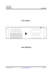
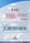
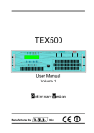
POS-1000T+
POS-1000T+
User Manual
User manual V1.2
www.posbroadcast.com
1 of 19
POS-1000T+
Contents
1. General Description
2. Installation and use Description
2.1 Preparation
2.2 Use
2.3 Settings and calibration
2.4 Front panel control
2.5 Software control
3. External Description
3.1 Front Panel
3.2 Rear Panel
3.3 Connector Description
4. Technical Specifications
4.1 Physical specifications
4.2 Electrical specifications
5. Working Principles
5.1 Power Supply
5.2 Regulate Board
5.3 LCD Board
5.4 Fuse Board
5.5 Control Board
5.6 PLL/VCO/Encoder Board
5.7 Interface Board
5.8 Power Amplifier Board
6. Internal Description
6.1 Internal View
7. Web browser application
User manual V1.2
3
4
4
4
4
5
8
11
11
12
13
14
14
14
16
17
17
17
17
17
17
18
18
19
19
19
www.posbroadcast.com
2 of 19
POS-1000T+
1. General Description
The POS-1000T++ is an exciter for Frequency Modulated audio broadcasting in a frequency
modulation able to transmit in the band between 87.5 and 108 MHz with an output RF power
adjustable up to a maximum of 1000 W
Outstanding audio features this device has are low distortion and inter modulation values
and the high signal to noise ratio. Another important feature the POS-1000T+ has is its great
simplicity of construction and use.
The POS-1000T+ was designed to be modular. Its various functions are run from modules
directly connected to each other with male and female connectors or with flat cables ending in
connectors. This type of design makes maintenance operations and any required module
replacement easier. All models are made with SMD technology.
This exciter contains a low-pass filter that reduces the harmonic emissions to below the
limits allowed by international regulations, and can therefore be used as a transmitter connected
directly to the antenna.
The machine is offered in two versions, one for Mono or MPX input (wideband input that is
useful when you want to transmit in stereo using an external stereo encoder) and the other with an
integrated stereo encoder. The POS-1000T+ stereo encoder guarantees excellent stereo separation
together with a low harmonic distortion level. Also the stereo version of the exciter can be
configured for operating in Mono/MPX mode (meaning excluding the stereophonic coder and using
the "left" input as the "mono" input and the BNC as the "MPX").
The user can do the configuration through micros witches that are accessible from the
outside. Both versions have two inputs (SCA1 and SCA2) for modulated signals on sub carriers
from special external encoders normally used in Europe for RDS (Radio Data System) transmission.
The microprocessor system includes an LCD display and push-button panel for inter action
with the user, and implements the following functions:
• Setting the output power
• Setting the operating frequency
• Measurement and display of the working parameters of the exciter
The exciter's management software is based on a menu system. The user can navigate
between the various submenus by using four push buttons: UP, DOWN, ENTER and ESC.
User manual V1.2
www.posbroadcast.com
3 of 19
POS-1000T+
2. Installation and use Description
This chapter contains the necessary information for installing and using the machine. In the
event any aspects are not completely clear, for example when using the machine for the first time,
we recommend you carefully read the entire description contained in this manual.
2.1 Preparation
Unpack the exciter and before doing any other operation, be sure it has not been damaged
during transport. In particular check that all the connectors are in perfect condition.
The main fuse can be accessed from the outside on the rear panel. Extract the fuse carrier
with a screwdriver to check its integrity or for replacement, if necessary. The fuse to be used is this
type 15A @220VAC
Check that the POS-1000T+ switches are in the "OFF" position. The exciter has one switch
for the mains power supply cable and completely interrupts the machine's mains power supply.
Connect the RF output of the exciter to the antenna cable or to a fictitious load 50 ohm.
Connect the mains cable.
Connect the earth cable.
Connect the audio cables of the signal source to the proper connectors on the back of the
exciter.
2.2 Use
Check that the POS-1000T+ switches are in the "ON" position.
Enter the "ESC" menu and “ENTER” to set the desired operating frequency.
By using the switches and trimmer found on the rear panel, set the characteristics
(impedance, pre emphasis and, if it’s necessary, stereo/mono) and the levels of the audio and RDS
input.
Set the desired power level from the LCD menu.
2.3 Settings and calibration
A trimmer for each one of the exciter's inputs is on the rear panel of the device. The printing
on the panel indicates which input each trimmer refers to. The sensitivity of the various inputs can
be adjusted using the trimmers within the limits described.
User manual V1.2
www.posbroadcast.com
4 of 19
POS-1000T+
•
Stereo or Mono mode
Switch 1: ON = Mono OFF = Stereo
Switch 2: No use
•
Stereo pre emphasis
50 us
•
75 us
Left and right input impedance
Switch1: ON = 600 ohm,
Switch2: ON = 600 ohm,
OFF = 10kohm
OFF = 10kohm
2.4 Front panel control
The machine is provided with a two-line LCD display where a set of menus is shown
When turned on, the LCD display shows the predefined screen with the graphic
representation of the instantaneous modulation level and indication of the direct power supplied:
The vertical bars under "MOD" indicate the progress of the modulation in real time; the
hatched bar signals the maximum nominal modulation level of 75 kHz (100%).
User manual V1.2
www.posbroadcast.com
5 of 19
POS-1000T+
To change the menu, select the UP or DOWN push button, the screen that is shown in following:
User manual V1.2
www.posbroadcast.com
6 of 19
POS-1000T+
2.4.1 Power setting
To change the set power level, select the menu power as below,
Keep the ENTER push button. The screen that is show in the modification mode is similar to
the following:
To increase the level, press the UP push button and to reduce it, press DOWN. As the set
level increases or decreases, the bar becomes longer or shorter to display the current setting. When
the designed level is reached, press ENTER to confirm and exit the predefined menu.
2.4.2 RF Power ON/OFF
To change the RF power ON or OFF, select the menu power as below,
2.4.3 Frequency setting
This menu lets you read and set the operating frequency.
Keep the ENTER push button. The screen that is show in the modification mode is similar to the
following:
User manual V1.2
www.posbroadcast.com
7 of 19
POS-1000T+
By pressing the ENTER push button, you can modify the set frequency using the UP (the
frequency increases) and DOWN push buttons. After having set a new frequency value, press the
ENTER push button to confirm the choice. The exciter will release from the current frequency and it
will latch onto the new operating frequency.
2.5 Software control
2.5.1 Software installation
To get the software, you can get software by CD Rom or download from www.posbroadcast.com.
Then, you can easy installation software on your computer.( refer to Window application)
2.5.2 Software monitor
When, you connect to the transmission via RS232 port and turn on, you can open the
software by the ways as
User manual V1.2
www.posbroadcast.com
8 of 19
POS-1000T+
After click open the software FM Monitor, you can get the symbol on bottom-right on your
computer.
Connected to transmitter
Can not connected to transmitter
FM Monitor symbol
(Connect to transmitter)
FM Monitor symbol
(Can’t connect to
transmitter)
Double click on the FM Monitor symbol; the software will be show as
User manual V1.2
www.posbroadcast.com
9 of 19
POS-1000T+
2.5.3 Software configuration
You can set the value as you’re requested. Then click SET, The parameter will be show and
change on LCD of the transmission.
• Power set > ON, the RF output of transmission is on.
OFF, the RF output of transmission is stanby.
• Frequency set > the values for frequency use.
• Forward target set > the values for RF output of transmission limit.
• Reflect target set > the values for maximum RF power reflect of transmission
protection limit.
• Temp protection set > the values for maximum temperature of transmission
protection limit.
The value from software FM Monitor should be related to LCD of transmission
LCD display
LCD display
LCD display
LCD display
User manual V1.2
www.posbroadcast.com
10 of 19
POS-1000T+
3. External Description
This chapter reports the elements of the front and rear panels of the POS-1000T+ with a
brief description of each of them.
3.1 Front Panel
[1] AIR FLOW
[2] POWER
[3] ON
[4] LOCK
[5] ALARM
[6] RF ON
[7] UP
[8] DOWN
[9] ENTER
[10] ESC
[11] DISPLAY
User manual V1.2
Grid for the intake of the air flow of the forced ventilation
ON/OFF switch. This switch disables the exciter without
disconnecting the mains supply
Green LED, light when the exciter is working
Green LED, light when the PLL is locked on the working
frequency
Red LED, light when the alarm function is operating
(Low power, high reflect power, high SWR or high
temperature)
Green LED, light when the exciter’s power output is on.
Push button to increase value.
Push button to decrease value.
Push button to confirm a parameter.
Push button to change and exit from a menu.
Liquid crystals display
www.posbroadcast.com
11 of 19
POS-1000T+
3.2 Rear Panel
[1] RIGHT/MONO
[2] RIGHT/MONO ADJ
[3] PREENPHASIS
[4] MODE
[5] FUSE
[6] RF OUTPUT
[7] RF TEST
[8] REMOTE
[9] INTERLOCK IN
[10] RS232
[11] INTERLOCK OUT
[12] IMPEDANCE
[13] LEFT-MONO
[14] LEFT-MONO ADJ
[15] MPX/RDS
[16] MPX/RDS ADJ
[17] SCA 1
[18] SCA1 ADJ
[19] SCA 2
[20] SCA2 ADJ
[21] 19 KHZ OUT
[22] GND
[23] PLUG
[24] AIR FLOW
User manual V1.2
XLR connector, balanced Right channel input
Adjustment trimmer for the Right channel input.
Dip-switch to set the pre emphasis at 50 or 75 µs. The pre
emphasis setting is only relevant for the Left and Right inputs
in stereo mode and for the mono input in mono mode, while
MPX input is unaffected by this setting.
Dip-switch to set the operation mode (STEREO or MONO).
Fuse holder. Use a screwdriver to access the fuse Contains
the general protection fuse rated 15 A
RF output connector, 7/16-type, 50Ω.
RF test output, approx. -60 dB of the RF output power level
DB15 connector for telemetry of the machine.
BNC interlock in connector: the exciter is forced in stand-by.
mode when the inner conductor is grounded.
DB9 connector for interconnection with other devices and for
factory parameters programming
BNC interlock out connector: the inner short to ground when
alarm is on.
Dip-switch to set the balanced input impedance, 600Ω or 10kΩ
XLR connector, balanced Left-Mono channel input.
Adjustment trimmer for Left-Mono channel input
BNC connector, MPX unbalanced input.
Adjustment trimmer for MPX input.
BNC connector, SCA1 unbalanced input
Adjustment trimmer for SCA1 input
BNC connector, SCA2 unbalanced input
Adjustment trimmer for SCA2 input
BNC output for the 19 kHz pilot tone. This can be used for
external devices (e.g. RDS coders) synchronization
Ground connect to earth
Mains supply plug, 180 - 240V 50-60 Hz
Grid for the intake of the air flow of the forced ventilation
www.posbroadcast.com
12 of 19
POS-1000T+
3.3 Connector Description
3.3.1 RS 232
Type: DB9 female
1
2
3
4
5
6
7
8
9
GND
TX
RX
NC
GND
NC
NC
NC
NC
3.3.2 Remote
Type: DB15 female
1
2
3
4
5
6
7
8
INTERLOCK IN
Frequency lock
GND
GND
NC
Forward
Reflect
PA voltage
9
10
11
12
13
14
15
INTERLOCK OUT
NC
GND
GND
Modulation level
PA temperature
PA current
3.3.3 Audio input LEFT/RIGHT
Type: XLR female
1
2
3
User manual V1.2
GND
Positive ( + )
Negative ( - )
www.posbroadcast.com
13 of 19
POS-1000T+
4. Technical Specifications
4.1 Physical specifications
Panel size
Depth
Weight
Working Temperature
483 mm (19”) x 132 mm (5 1/4”) (3U)
610 mm (24”)
20 Kg
0 °C ÷ 50 °C
4.2 Electrical specifications
General
RF output power
RF output connector
RF output impedance
Frequency range
Frequency setting
Frequency step
Frequency stability
Modulation type
Spurious and Harmonics suppression
Modulation capability
A.C. power supply
Power consumption
0 to 1000 W, adjustable
7/16 – type Female
50 Ohm
87.5 MHz ÷ 108 MHz
software programming
50 KHz (10 KHz on request)
±2ppm from -10°C to 50°C
direct carrier modulation
respects FCC and CCIR standards
(Typical -75 dBc)
respects relevant FCC and CCIR standards
≅ 180 V ÷ 240 V
1700 VA
Input
Left, Right and Mono Input
MPX input
Input impedance
MPX input impedance
Input level
Pre emphasis
SCA/RDS input
SCA/RDS input impedance
SCA/RDS input level
SCA/RDS amplitude/frequency response
Type: XLR female balanced
Type: BNC, unbalanced
balanced input: 600 or 10 k Ohm selectable
unbalanced input 10 k Ohm
-13 dBm ÷ +13 dBm, adjustable
Selectable:
0
50 us (CCIR)
75 us (FCC)
3 BNC unbalance
10 kOhm
-20 dBm ÷ +13 dBm, adjustable
± 0.2 dB, 40 kHz to 100 kHz
Output
RF Out
RF test
19 kHz pilot tone output
User manual V1.2
7/16 – type Female, 50 Ohm
BNC connector, -60 dB.
BNC connector, 1.3 Vp-p.
www.posbroadcast.com
14 of 19
POS-1000T+
MONO operation
S/N
Amplitude frequency response
Total harmonic distortion (THD)
> 70dB
± 0.5 dB, 20Hz ÷ 15 KHz
< 0.05%
MPX operation
Composite S/N
MPX amplitude frequency response
MPX Total harmonic distortion (THD)
Stereo separation
> 70dB
± 0.1 dB, 20 Hz ÷ 53 KHz
± 0.2 dB, 53 KHz ÷ 100 KHz
< 0.02 %
> 50 dB
Stereo operation
S/N FM Stereo
Audio frequency response
Total harmonic distortion (THD)
Stereo separation
> 70 dB
20 Hz ÷ 15 KHz
≤ 0.05 %
> 50 dB
Connections
Interlock connector
Serial interface
Remote
User manual V1.2
2 BNC
DB9 female RS232
DB15 female
www.posbroadcast.com
15 of 19
POS-1000T+
5. Working Principles
5.1 Power Supply
POS-1000T+ power supply is a switching type of unit, and its main 24V 2.5A, 12V 8.5A and
48 V 32A output feeds the RF amplifier and regulate broad of the machine. The power supply is
connected to voltage between 180 and 240 V without having to make adjustments or manual
settings.
5.2 Regulate Board
The regulate board for generating continuous 5 V 12V 15V and 20 V voltages for powering
the other circuits on the device are present on the power supply.
5.3 LCD Board
The LCD board contains the microcontroller (PIC18F458) that implements the machine's
control software, the display and the other components needed to interface the user. The board
interfaces with the other machine modules, both for power supply distribution and for the control and
measures.
5.4 Fuse Board
The fuse board contains the fuse, current, temperature and voltage sensor. The board
interfaces with the other machine modules, both for power supply, power amplifier and for the
control. This circuit carries out the following functions:
• Measures current and voltage
• Measures temperature
5.5 Control Board
The control board contains the measure and control parameter (forward, reflect, voltage,
current, temperature, bias etc.). The board interfaces with the other machine modules, both for LCD
and power amplifier board.
5.6 PLL/VCO/Encoder Board
The PLL/VCO/Encoder board card carries out the following functions:
5.6.1 Encoder section
The encoder audio input section contains the circuits that perform the following functions:
•
Input impedance selection
•
15 KHz filtering
•
Pre emphasis selection
•
Mixing of the signal, MPX and SCA channels
•
Stereo multiplexing
•
19 KHz generate
•
Measurement of the modulating signal
•
Measurement of the left and right signal
User manual V1.2
www.posbroadcast.com
16 of 19
POS-1000T+
5.6.2 PLL section
The PLL section of the card generates the signal in modulated radio frequency. It is based
on a PLL diagram that uses an MC145170 type of integrated PLL. For frequency reference use to
4.000 MHz
5.6.3 VCO section
The VCO section of the card generates the signal in fm band 87.50 – 108 MHz. It is based
on a VCO diagram that uses to 8 varicap tuning diode and MAR-8 low noise amplifier.
5.7 Interface Board
The interface board needed to interface from LCD board and external machine for setup or
monitoring.
5.8 Driver Board
The RF signal coming from the VCO, is amplified and is then sent to the first stage that sees
to its amplifications up to 30W.The amplifier is made in two stages. The first is made with BGF35,
and the last with one BLF175.
5.9 Power Amplifier Board
The final power stage is enclosed in a totally shielded metal container fastened in the centre
of the device. The RF signal coming from the exciter sent to the splitter, amplifier, combiner, low
pass filter and directional coupler stage that sees to its final amplifications up to 1000W.The
amplifier is made in three modules. Every RF module supplied up to 350W.This active device used
in amplifier module is a Mosfet (SD2942). These amplifier modules combine with Wilkinson Splitter
and Combiner in strip line.
5.10 LPF Board
This board is mean Low Pass Filter (LPF) is function is to suppress the harmonic
components generate by the amplifier below the level required by regulations. This board includes a
direction coupler, is function is the measurement of the forward, reflect output power and RF sample
at –60dB.
User manual V1.2
www.posbroadcast.com
17 of 19
POS-1000T+
6. Internal Description
6.1 Top view
The figure below shows the view from above the machine,
1
8
2
9
3
10
5
4
11
12
6
13
14
7
15
1. PLL/VCO/Encoder board
2. Power supply 12V 8A
3. Regulate board
4. Power factor correction unit
5. Power supply unit 32A @48V
6. Control board
7. LCD board
8. Directional coupler
9. Low Pass Filter
10. Power Combiner
11. Power amplifier ( SD2942 X 3 )
12. Power Splitter
13. Fuse board
14. Coupler power input board
15. Blower
User manual V1.2
www.posbroadcast.com
18 of 19
POS-1000T+
7. Web browser application
You can monitor and configuration all parameter to transmitter via web browser. It
easy to connect anywhere and update status your transmitter. Please see application on
www.posbroadcast.com/telemetry
User manual V1.2
www.posbroadcast.com
19 of 19