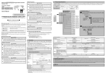
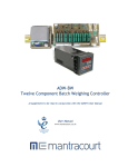
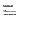
1
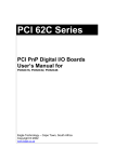
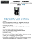
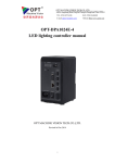
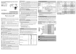
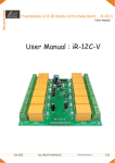
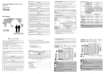
8-Channel Relay Output Board
Via I2C, USB Protocol
P/N KA-I2C-8-RL-PWR-TH
I2C-USB-Relay8
User Manual
Page 1 / 16
Manufacturer P/N KA-I2C-8-RL-PWR-TH-000I
Revision I, April 2013
8-Channel Relay Output Board
Via I2C, USB Protocol
P/N KA-I2C-8-RL-PWR-TH
Table of Contents
What Does it Do?.............................................................................................................................................. 3
What Do I Need to Make it Work?................................................................................................................... 3
What Else Does it Work With?......................................................................................................................... 4
How to Use This Device, USB ......................................................................................................................... 5
Powering Up the I2C-USB-Relay8............................................................................................................... 5
Using the I2C-USB-Relay8 .......................................................................................................................... 5
How to Use This Device, I2C............................................................................................................................ 6
Setting Up the Controller .............................................................................................................................. 6
Connecting to the I2C Communications Port................................................................................................ 6
IDC connector J2 ...................................................................................................................................... 6
Terminal Blocks TB18-TB19 ................................................................................................................... 7
Setting the I2C Address................................................................................................................................. 7
Using the I2C-USB-Relay8 .......................................................................................................................... 8
Illustrations ..................................................................................................................................................... 10
Technical Specifications ................................................................................................................................. 15
Disclaimers ..................................................................................................................................................... 16
Page 2 / 16
Manufacturer P/N KA-I2C-8-RL-PWR-TH-000I
Revision I, April 2013
8-Channel Relay Output Board
Via I2C, USB Protocol
P/N KA-I2C-8-RL-PWR-TH
What Does it Do?
The I2C-USB-Relay8 is designed to generate digital output to up to 8 independent
sources. It uses Power Relays to create this output.
Each output port on the I2C-USB-Relay8 has an LED indicator light which activates
when the port is activated.
The I2C-USB-Relay8 is modular and expandable; in addition to being stackable, it
can be assigned 1 of up to 16 unique addresses and monitored via the on-board I2C
communications port.
You can also communicate to the I2C-USB-Relay8 via the USB port.
What Do I Need to Make it
Work?
If you are going to use I2C communications to drive this module, you will need:
• Controller module
o USB-I2C-Relay10
o USB-I2C-RS232-Micro
o WEB-I2C-Remote
o Your own custom I2C controller module
• 10-pin IDC connector, preferably in the form of a female-female ribbon cable
• 14-22 AWG wire, for connecting ports to output sources, supplying power and
I2C communications port
Page 3 / 16
Manufacturer P/N KA-I2C-8-RL-PWR-TH-000I
Revision I, April 2013
8-Channel Relay Output Board
Via I2C, USB Protocol
P/N KA-I2C-8-RL-PWR-TH
If you are going to use USB communications to drive this module, you will need:
• USB cable
You will also need:
• Power Supply
o 7.5VDC @ 600mA maximum
o Can be brought in via on-board terminal block TB17
o Can be brought in via I2C port
o Or can be powered by USB
What Else Does it Work With?
The I2C-USB-Relay8, in addition to interfacing with your own custom applications,
can be used with a PC running LabView version 7 or later and a USB-I2C-Relay10
control module (see Figure 1).
Simply connect your PC to the control module via USB, connect your I2C-USBRelay8 module to the controller via the I2C module, and from there use our LabView
drivers to observe the state of all 8 input ports in real-time on up to 2 I2C-USBRelay8 modules.
The I2C-USB-Relay8 module can also be used with:
• I2C-Opto8
• USB-I2C-RS232-Micro (stand-alone unit programmed via PC)
• WEB-I2C-Remote (stand-alone server which executes commands via
Ethernet connection)
You can also have I2C-USB-Relay8 modules working side-by-side with I2C-Opto8
input modules on the same controller.
Page 4 / 16
Manufacturer P/N KA-I2C-8-RL-PWR-TH-000I
Revision I, April 2013
8-Channel Relay Output Board
Via I2C, USB Protocol
P/N KA-I2C-8-RL-PWR-TH
How to Use This Device, USB
Powering Up the I2C-USB-Relay8
The device can be powered directly from the USB cable if the source is capable of
providing 500mA. Generally powered USB hubs or USB ports directly on your PC’s
motherboard support this.
Alternatively you can power the device via a 7.5VDC connection to TB17.
Using the I2C-USB-Relay8
Once your I2C-USB-Relay8 is powered up and connected to your PC, use the
software of your choice to transmit a single byte to the USB device. The least
significant bit corresponds to relay 1 and the most significant bit to relay 8.
Page 5 / 16
Manufacturer P/N KA-I2C-8-RL-PWR-TH-000I
Revision I, April 2013
8-Channel Relay Output Board
Via I2C, USB Protocol
P/N KA-I2C-8-RL-PWR-TH
2
How to Use This Device, I C
Setting Up the Controller
Perhaps your preference is for stand-alone operation, or remote accessibility, or a
setup which doesn’t rely on an Ethernet connection. Whichever controller you
choose, there are distinct advantages to each model.
While operation of your controller can be as simple as plugging your controller into
your power source and then connecting the I2C-USB-Relay8 to your controller, we
strongly encourage you to refer to the setup directions in the documentation for your
controller.
Connecting to the I2C Communications
Port
Connecting to the I2C communications port on your I2C-USB-Relay8 can be done in
one of two ways:
IDC connector J2
These connectors are also known as 10-pin IDC connectors. Generally what you
plug into these are female-female ribbon cables which look like the illustration found
in Figure 2. The pinout for these connectors is illustrated in Figure 3.
Page 6 / 16
Manufacturer P/N KA-I2C-8-RL-PWR-TH-000I
Revision I, April 2013
8-Channel Relay Output Board
Via I2C, USB Protocol
P/N KA-I2C-8-RL-PWR-TH
Terminal Blocks TB18-TB19
The specific pins you need for I2C communications are:
•
•
•
•
TB19, “SDA”
TB20, “SCL”
TB18, “GND”
TB19, “5V”
Setting the I2C Address
Each unit operating on the same I2C communications bus must have a unique
address. Since the selectable I2C address space consists of 2 base addresses with
3 configurable bits each, up to 16 unique devices can share the same I2C
communications bus.
On the I2C-USB-Relay8, the I2C address is configured with four jumpers (1 for each
bit of the address). Figure 5 shows you where to find these jumpers.
The jumper across pins 4 and 5 of J4 set the base address. With the jumper set,
the base address is 0100xxx0, unset it is 0111xxx0.
To set the second bit of the address to “1”, short the “HI” and “ADR” pins of JP3
together. To set the second bit to “0”, short the “LO” and “ADR” pins of JP3
together. Repeat with JP4 and JP5 to set the third and fourth bits of the address.
Page 7 / 16
Manufacturer P/N KA-I2C-8-RL-PWR-TH-000I
Revision I, April 2013
8-Channel Relay Output Board
Via I2C, USB Protocol
P/N KA-I2C-8-RL-PWR-TH
Using the I2C-USB-Relay8
Once your I2C-USB-Relay8 is connected to your controller and the unit’s address is
configured, how exactly you actually use the product will rely heavily on the
controller interface.
If you are not using one of our controller units, your controller must write 2 bytes of
information onto the I2C bus each time you wish to change the state of 1 or more
channels – a byte for the address of the board you want to talk to, and a byte that
represents which relays should be engaged and which relays should be
disengaged.
Bit 7
0
Bit 6
1
Address Byte – J4 unset
Bit 5 Bit 4 Bit 3 Bit 2
1
1
X
X
A2
A1
(JP5) (JP4)
Bit 1 Bit 0
X
0
A0 R/ W
(JP3)
Status Byte
Bit 7
X
RL8
Bit 6
X
RL7
Bit 5
X
RL6
Bit 4
X
RL5
Bit 3
X
RL4
Bit 2
X
RL3
Bit 1
X
RL2
Bit 0
X
RL1
So, writing “011100010” for the address byte and “00001111” for the status byte
means that the unit at address 1 will turn relays RL1-4 on and relays RL5-RL8 off.
Page 8 / 16
Manufacturer P/N KA-I2C-8-RL-PWR-TH-000I
Revision I, April 2013
8-Channel Relay Output Board
Via I2C, USB Protocol
P/N KA-I2C-8-RL-PWR-TH
Communications Failsafe
Place a jumper on JP2 (see figure 6) to force all relays to open when
communications are interrupted for more than a quarter of a second. Without a
jumper on JP2, relays will retain their state until a new command is issued or power
is removed.
Page 9 / 16
Manufacturer P/N KA-I2C-8-RL-PWR-TH-000I
Revision I, April 2013
8-Channel Relay Output Board
Via I2C, USB Protocol
P/N KA-I2C-8-RL-PWR-TH
Illustrations
Figure 1: Screen view of LabView interacting with the I2C-USB-Relay8.
Page 10 / 16
Manufacturer P/N KA-I2C-8-RL-PWR-TH-000I
Revision I, April 2013
8-Channel Relay Output Board
Via I2C, USB Protocol
P/N KA-I2C-8-RL-PWR-TH
Figure 2: IDC Female-Female
Ribbon Cable
Figure 3: IDC Connector Pinout
Page 11 / 16
Manufacturer P/N KA-I2C-8-RL-PWR-TH-000I
Revision I, April 2013
8-Channel Relay Output Board
Via I2C, USB Protocol
P/N KA-I2C-8-RL-PWR-TH
Figure 4: Ribbon connector port J2, and the alternative terminal block pins needed
for I2C communications.
Page 12 / 16
Manufacturer P/N KA-I2C-8-RL-PWR-TH-000I
Revision I, April 2013
8-Channel Relay Output Board
Via I2C, USB Protocol
P/N KA-I2C-8-RL-PWR-TH
Figure 5: I2C Address Jumpers JP3-JP5 and J4.
Page 13 / 16
Manufacturer P/N KA-I2C-8-RL-PWR-TH-000I
Revision I, April 2013
8-Channel Relay Output Board
Via I2C, USB Protocol
P/N KA-I2C-8-RL-PWR-TH
Figure 6: Communications failsafe jumper JP2.
Page 14 / 16
Manufacturer P/N KA-I2C-8-RL-PWR-TH-000I
Revision I, April 2013
8-Channel Relay Output Board
Via I2C, USB Protocol
P/N KA-I2C-8-RL-PWR-TH
Technical Specifications
Number of Output Ports
Arrangement
Contact Materials
Input Port Voltage
Maximum Switching
Max. allowable Voltage
Max allowable current
Operating humidity
Ambient Temperature
Unit Weight
Form Factor
8
8 Form C, SPDT
Optically isolated
5VDC, 5mA minimum
100 Hz
30VDC
12mA
10-80% RH non-condensing
0 to 60 C (with no icing)
About 120 grams (4.3oz)
64 mm W x 252 mm L (2.5" X
9.9")
Total Power Consumption 7.5VDC @ 500mA max.
Short-Circuit Protection 1.5A with resettable PTC fuse
Power Indicator Green LED
Page 15 / 16
Manufacturer P/N KA-I2C-8-RL-PWR-TH-000I
Revision I, April 2013
8-Channel Relay Output Board
Via I2C, USB Protocol
P/N KA-I2C-8-RL-PWR-TH
Disclaimers
THIS PRODUCT IS PROVIDED "AS-IS," "AS AVAILABLE," AND ALL
WARRANTIES, EXPRESS OR IMPLIED, ARE DISCLAIMED
(INCLUDING BUT NOT LIMITED TO THE DISCLAIMER OF ANY
IMPLIED WARRANTIES OF MERCHANTABILITY AND FITNESS FOR A
PARTICULAR PURPOSE). THE SOLE AND ENTIRE MAXIMUM
LIABILITY OF CADX SERVICES, INC., FOR ANY REASON, AND
BUYER'S SOLE AND EXCLUSIVE REMEDY FOR ANY CAUSE
WHATSOEVER, SHALL BE LIMITED TO THE AMOUNT PAID BY THE
CUSTOMER FOR THE PARTICULAR ITEMS PURCHASED. CADX
SERVICES, INC. AND ANY OF ITS AFFILIATES, DEALERS OR
SUPPLIERS ARE NOT LIABLE FOR ANY INDIRECT, SPECIAL,
INCIDENTAL, OR CONSEQUENTIAL DAMAGES (INCLUDING
DAMAGES FOR LOSS OF BUSINESS, LOSS OF PROFITS,
LITIGATION, OR THE LIKE), WHETHER BASED ON BREACH OF
CONTRACT, BREACH OF WARRANTY, TORT (INCLUDING
NEGLIGENCE), PRODUCT LIABILITY OR OTHERWISE, EVEN IF
ADVISED OF THE POSSIBILITY OF SUCH DAMAGES. THE
LIMITATIONS OF DAMAGES SET FORTH ABOVE ARE
FUNDAMENTAL ELEMENTS OF THE BASIS OF THE BARGAIN
BETWEEN CADX SERVICES, INC. AND BUYER. THIS PRODUCT
WOULD NOT BE PROVIDED WITHOUT SUCH LIMITATIONS. SOME
STATE STATUTES MAY APPLY REGARDING LIMITATION OF
LIABILITY.
Page 16 / 16
Manufacturer P/N KA-I2C-8-RL-PWR-TH-000I
Revision I, April 2013