1
ADW-BW
Twelve Component Batch Weighing Controller
A Supplement to be read in conjunction with the ADW15 User Manual
User Manual
www.mantracourt.co.uk
Contents
ADW-BW 12 Component Batch Weigher ............................................................................................ 1
ADW-BW Component Batch Weighing Controller .................................................................................... 2
Introduction ............................................................................................................................... 2
Specifications ............................................................................................................................. 3
Batch Controller System Description .................................................................................................. 3
ADW-BW Indicator Controller........................................................................................................... 4
The Relay Output Module ............................................................................................................... 4
Set Up Parameters........................................................................................................................ 4
Hardware Configuration ................................................................................................................. 5
Procedure .................................................................................................................................. 5
Alarm Conditions.......................................................................................................................... 5
Communications to be read in Conjunction with Chapter 7 of the ADW15 User Manual..................................... 7
Response to Command 1 from ADW ................................................................................................... 7
Response to Command 2 ................................................................................................................ 9
BW Relay Status Flags................................................................................................................... 10
Data Returned from Command 2 Bytes 30 & 31 .................................................................................... 10
ADW-BW Alarm Status Flags ........................................................................................................... 10
Data Returned from Command 2 Byte 28............................................................................................ 10
ADW BW Option 1, (no menu selection) (DA=8 (15)) .............................................................................. 11
ADW BW Option 2, (with menu selection (DA=24 (31)) ........................................................................... 12
ADW BW Option 3, (no menu selection (DA= 0 (7)) ................................................................................ 13
ADW BW Option 4, (with menu selection (DA = 16 (23)) .......................................................................... 14
Batch Weigher ADW/BW Procedure .................................................................................................. 15
W A R R A N T Y .......................................................................................................................... 16
ADW-BW 12 Component Batch Weigher
Designed around the highly successful Mantraweigh ADW15, Strain gauge Amplifier/Controller, and Remote Multi Set
Point system; The ADW-BW Batch Weigher special software program, makes provision for the weighing and mixing of
up to 12 components. An option is available to select from 10 possible menus using an additional I/O module and
BCD switch.
Programming for the system parameters is achieved by the ADW15 keypad, with an option to carry out the operation
via communications port from a remote PC or PLC.
Ingredients mix times, weight checks, settle times and tolerance settings are all features of this comprehensive
software program. To ensure system integrity, activities are constantly monitored with an Alarm condition being
activated where appropriate.
Very simple auto-calibration routines make this an extremely easy system to set up.
All batch details and weights will be recorded on an optional printer if necessary.
The Batch Weigher is part of a family of special Weighing, Filling and Throughput Control Systems offered by
Mantracourt Electronics Limited.
Mantracourt Electronics Limited ADW-BW User Manual
1
ADW-BW Component Batch Weighing Controller
features
Upto 12 Components
Inflight compensation for all components
Selectable batch totals
Manual or PLC operation
Password security
Din rail relay module contact rating 240V @ 5A AC
Options
Supplies for 110/240 VAC or 12/24 VDC
Optional 10 Menu selection
Easy calibration
Mixer timing
Panel display sealed to IP65
Excitation for up to 4 strain gauges
Accessories
IF25 Interface Module Connects up to 25 Batch
Weighing Controller to one RS232 port
Communications Port PLC or PC
Printer Drive
Menu Selection
Introduction
Designed around the ADW15 Strain gauge Indicator Controller, and the remote set point relay unit.
The batch controller system software makes provision for the mixing of up to 12 components
In 10 possible menus (see options). Programming from the ADW-BW, keypad allows for the control of quantities from
each of the feeds, and the number of batches required.
Ingredient mix times, weight checks, and settle times are all features of the comprehensive software control within
the ADW-BW.
With the inclusion of interface boards, full remote control can be affected from a PC or PLC, and a printed record of
all the required activity can be taken onto a printer.
2
Mantracourt Electronics Limited ADW-BW User Manual
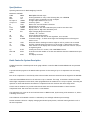
Specifications
Operating Instructions for Batch Weighing Controller
Mnemonics Available
Code
Value
REP
1-10
PASS
1111
SP1 upto 12
±19999
±19999
IF1 upto 12
bt
1-255
0-19999
tl
±19999
CALL
±19999
CALH
dA
0-31
dP
Sttl
t0L
0-5
0-255
0-19999
bdt
IIt
ICA
1-255
1-255
1-19999
Cp
SdSt/Lab
0-129
0-254
rS
0-255
Description Selected recipe
Security password for entry to the following data, set in EEPROM
Set point 1 upto 12 'Desired' trip level of outputs
In-flight compensation for SP 1 to 12
Actual trip points
= SP - IF
Batch total. Sets total number of batches
Mixing time set in seconds
Display value for 'Low' auto calibration point, must be less than 'CALH'
Display value for 'High' auto calibration point.
Input averaging & options selection
+8= BW5, +16 = 10 menu
Selects decimal point position
Settle time before auto tare of next ingredient, set in seconds
Tolerance Settings - To check mixer hopper has discharged before allowing next
batch to start
Delay time before checking increase in weight on call for product. Set in seconds
Increase in weight check time interval. Set in seconds 1->255 Increase in weight
check amount i.e. the display must increase in weight check time interval. (1It).Set
in engineering units
Comms protocol 0-127 = Printer, 128 = 'MANTRABUS Format'
Serial device station number to set the units 'address' when the communications port
is used.
Sets display resolution
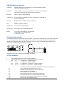
Batch Controller System Description
The Batch Controller is based upon the strain gauge indicator controller ADW15 and the REM 8 multi set point DIN
rail units.
A special software program in the ADW15 makes provision for the mixing of up to 12 components into one mixing
vessel.
Each of the components is controlled by values selected under mnemonics entered from the keypad of the ADW-BW.
A BCD switch with REM16I allows for the selection of up to 10 menus. The range of mnemonics include Set Points
and In-flight compensation valves which, when programmed set the conditions for a relay to operate, controlling the
operation of valves and therefore the amount of component from each feed into the mixer/weigh vessel.
A batch control mnemonic 'bt' provides a batch total which controls the desired number of mixes from the
components feeds. This value can be set from 1 to 255 batches.
The components mix time can be set from between 0 to 19999 seconds, by the setting of the mnemonic 'tl', before
a discharge is activated.
Auto calibration of the ADW15 controller is achieved by 'low' and 'high' calibration point settings.
Further mnemonics allow for a display averaging and decimal point position, and settle time figure before call of
the next component.
Mantracourt Electronics Limited ADW-BW User Manual
3
ADW-BW Indicator Controller
Calibration
Automatic digital by use of keypad and 1 (or 2) known weights. Manual
calibration can also be selected
Sensitivity
± 0.95 to 3.8mV/V for full scale. (Factory set to 2.5mV/V.) User analogue
calibration if required by link change and 15 turn trimmers
Excitation
10V d.c. nominal, 150mA maximum
Compensation
By ± sense wire to compensate for cable, connection volt drops and any
variation in 10V supply
Accuracy
90 days ± 0.08% of reading ± 0.05% of FSD typical
Drift
0.002%/ºC typical @ 2.5mV/V
Display Rate
0.1 seconds for standard update
Input Average
Set by keypad, up to 64 standard updates
Display
1 x 4.5 digit, High brightness, 10mm Red LED
2 x 3mm LED's for SP1 and SP2 status
1 x 3mm LED for hold
The Relay Output Module
The module consists of 8 relays rated at 240 volts 5 Amps - SPCO, Alarm via 30V 50mA NC contact, DIN rail mounted
for a G or top hat profile. Each relay is plugg-able and connections are made by 2.5mm field screw terminals.
Indication of relay status is shown by LED's. Trip points volt free contact. The module can be situated up to 2
metres from the ADW strain gauge indicator controller.
Supplement To be read in conjunction with ADW15 user Manual
Set Up Parameters
1
2
i)
ii)
iii)
iv)
v)
vi)
vii)
viii)
ix)
4
Enter the password to proceed with set up parameters.
Enter system parameters i.e. 5 or 12 Components under (DA) as follows:DA
0-7
= 12 components + display averaging
DA
8 -15 = 5 components + display averaging
DA
16 -23 = 12 components + menu select + display averaging
DA
24 - 31 = 5 components + menu select + display averaging
Note: The selection of 5 components reduces the menu size to SP1-5 and IF1-5
Enter required set point values for SP1 to SP12
Enter batch total required (bt)- must be 1 or greater
Enter mixing time in seconds (tL)
Enter the settle time in seconds (Sttl)
Enter Tolerance settings for mixer hopper empty (tol)
Enter delay time before, increase in weight check (bdt)
Enter increase in weight check timer interval in seconds (IIt)
Enter increase in weight amount (ICA)
Mantracourt Electronics Limited ADW-BW User Manual
Calibration settings CALL and CALH together with auto tare, display, averaging and decimal point selection can be
set independently of the controller system as described in the ADW15 user manual.
In Flight values (IF1-IF12) should be determined after running an initial batch.
Hardware Configuration
Relays RL1 to RL8 of REM8 (1) and RL1 to RL4 of REM8 (2) operate the set points SP1 to SP12 (and corresponding in
flight IF1 to IF12), as required for the number of components in the mix. Components can be omitted by setting
their corresponding SP values to zero.
Relay RL6 of REM2 operates the mix time running.
Relay RL7 of REM2 operates the discharge.
Relay RL8 of REM2 operates the batch in progress.
Procedure
1. Start signal from 'reset' terminals on the ADW-BW. (This doubles as start batch and start mix contact).
2. The batch in progress relay (RL8) operates, the ADW15 auto tares and calls for the first component. The first set
point relay operates (e.g. SP1 = RL1 relay).
3. When SP1 is achieved, the relay drops out and after the programmed settle time, the unit auto tares and the
next relay operates (e.g. SP2 = RL2 relay).
4. When SP2 is achieved, the relay drops out and after the programmed settle time, the unit auto tares and the
next relay operates (eg SP3 = RL3 relay).
The sequence is repeated for up to 12 components as required.
If the set point = 0 then that relay is omitted
5. On completion of the discharge i.e. the container weight returned to zero, within the tolerance programmed,
'tol' the relay R7 drops out.
6. The system will now be ready for a further mix to take place. This is achieved by a further press of the start
batch/next mix contact, the unit auto tares and the sequence is repeated.
7. On completion of the last mix, the start batch/next mix contact is again pressed to acknowledge that the batch
is complete. The batch in progress relay now drops out.
This completes the batch sequence.
Alarm Conditions
(Defined as contacts open on SP3 via AN+/AN- on the ADW15 rear panel)
1. Loss of communications to the REM units will cause the display to flash at a rate of once per second. This is a self
cancelling alarm.
2. A 'NO' increase in weight as determined by 'IIt and ICA' after the time programmed for 'bdt', will cause an alarm
(This alarm will be cancelled if the component reaches its set point value).
3. An alarm reset is achieved by a contact closure on input1 of the J4 on the REM8.
4. An 'ABORT FUNCTION' function is achieved by a contact closure on input 2 of J4 on the REM8. This will remove
all 'CALLS' leaving the ADW-BW waiting to discharge its contents if the ADW-BW, is however, running the mix
time, then this time will finish before discharging. On discharge being complete a 'NEXT FILL/START ' signal will
cancel the batch in progress relay.
Mantracourt Electronics Limited ADW-BW User Manual
5
Note:
i)
ii)
iii)
6
When a mixing sequence is in operation, it is not possible to enter the menu
The alarm condition is achieved by the SP3 contact board replacing the
analogue output connections on the rear of the ADW15
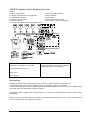
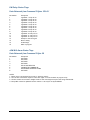
The minimum system hardware requirement is:
1 x ADW-BW
1 x REM8
1 x REM PSU
1 x REM C1 cable
(See option 1. Diagram for details)
Mantracourt Electronics Limited ADW-BW User Manual
Communications to be read in Conjunction with Chapter 7 of the ADW15 User Manual
DEC
1
2
3
4
5
6
7
8
9
10
11
12
13
14
15
16
17
18
19
20
21
22
23
24
25
26
27
28
29
30
31
32
33
34
35
36
37
38
39
40
41
42
43
44
45
46
47
48
49
50
HEX
1
2
3
4
5
6
7
8
9
A
B
C
D
E
F
10
11
12
13
14
15
16
17
18
19
1A
1B
1C
1D
1E
1F
20
21
22
23
24
25
26
27
28
29
2A
2B
2C
2D
2E
2F
30
31
32
Description
REQUEST ALL VARIABLES
REQUEST DISPLAY DATA
INHIBITED RETURN NAK
UPDATE SET POINT 1
UPDATE IN-FLIGHT 1
UPDATE SET POINT 2
UPDATE IN-FLIGHT 2
UPDATE SET POINT 3
UPDATE IN-FLIGHT 3
UPDATE SET POINT 4
UPDATE IN-FLIGHT 4
UPDATE SET POINT 5
UPDATE IN-FLIGHT 5
UPDATE SET POINT 6
UPDATE IN-FLIGHT 6
UPDATE SET POINT 7
UPDATE IN-FLIGHT 7
UPDATE SET POINT 8
UPDATE IN-FLIGHT 8
UPDATE SET POINT 9
UPDATE IN-FLIGHT 9
UPDATE SET POINT 10
UPDATE IN-FLIGHT 10
UPDATE SET POINT 11
UPDATE IN-FLIGHT 11
UPDATE SET POINT 12
UPDATE IN-FLIGHT 12
UPDATE BATCH TOTAL
UPDATE MIXER TIMER
INHIBITED. RETURNS A 'NAK'
INHIBITED. RETURNS A 'NAK'
INHIBITED. RETURNS A 'NAK'
INHIBITED. RETURNS A 'NAK'
UPDATE DISPLAY AVERAGES
UPDATE DECIMAL POINT
UPDATE SETTLE TIME
UPDATE TOLERANCE FOR RETURN TO START WEIGHT
UPDATE BLOWER DELAY TIME
INCREASE IN WEIGHT TIMER
INCREASE IN NUMBER OF DIGITS
COMMS PROTOCOL
CAN NOT BE WRITTEN TO
UPDATE RESOLUTION
EEPROM ENABLE/DISABLE
START BATCH
START NEXT MIX
STOP AT END OF MIX
SET ALARM RELAY
CLEAR ALARM RELAY
ABORT MIX
(AS ADW15)
(AS ADW15)
(rEC)
(SP1)
(IF1)
(SP2)
(IF2)
(SP3)
(IF3)
(SP4)
(IF4)
(SP5)
(IF5)
(SP6)
(IF6)
(S7)
(IF7)
(SP8)
(IF8)
(SP9)
(IF9)
(SP10)
(IF10)
(SP1)
(IF11)
(SP12)
(IF12)
(bt)
(t1)
(DA)
(DP)
(ST)
(TOL)
(Bdt)
(Ht)
(ICA)
(Cp)
(STST)
(Rs)
Response to Command 1 from ADW
Mantracourt Electronics Limited ADW-BW User Manual
7
Byte
1
2,3
4,5
6,7
8,9
10,11
12,13
14,15
16,17
18,19
20,21
22,23
24,25
26,27
28,29
30,31
32,33
34,35
36,37
38,39
40,41
42,43
44,45
46,47
48,49
50,51
52,53
54,55
56,57
24,25
26,27
28,29
30,31
32,33
34,35
36,37
38,39
40,41
42,43
44,45
46,47
48,49
50,51
52,53
54,55
56,57
58,59
60,61
62,63
64,65
8
Station number
DISPLAY
RECIPE
SET POINT 1
IN FLIGHT 1
SET POINT 2
IN FLIGHT 2
SET POINT 3
IN FLIGHT 3
SET POINT 4
IN FLIGHT 4
SET POINT 5
IN FLIGHT 5
SET POINT 6
IN FLIGHT 6
SET POINT 7
IN FLIGHT 7
SET POINT 8
IN FLIGHT 8
SET POINT 9
IN FLIGHT 9
SET POINT 10
IN FLIGHT 10
SET POINT 11
IN FLIGHT 11
SET POINT 12
IN FLIGHT 12
BATCH TOTAL
MIXER TIMER
IN FLIGHT 5
SET POINT 6
IN FLIGHT 6
SET POINT 7
IN FLIGHT 7
SET POINT 8
IN FLIGHT 8
SET POINT 9
IN FLIGHT 9
SET POINT 10
IN FLIGHT 10
SET POINT 11
IN FLIGHT 11
SET POINT 12
IN FLIGHT 12
BATCH TOTAL
MIXER TIMER
A/D COUNTS FOR LOW CALIBRATION POINT
A/D COUNTS FOR HIGH CALIBRATION POINT
DISPLAY FOR LOW CALIBRATION POINT
DISPLAY FOR HIGH CALIBRATION POINT
Mantracourt Electronics Limited ADW-BW User Manual
66,67
68,69
70,71
72,73
74,75
76,77
78,7
80,81
82,83
84,85
86
87
88
DISPLAY AVERAGE
DECIMAL POINT
SETTLE TIME
TOLERANCE FOR RETURN TO START WEIGHT BLOWER DELAY
TIME
INCREASE IN WEIGHT TIMER
INCREASE IN NUMBER OF DIGITS
PROTOCOL
SDST
RESOLUTION
EEPROM ENABLE/DISABLE FLAG
RELAY STATUS (RELAYS 1-8)
EXOR CHECKSUM OF THE ABOVE DATA
(DA)
(DP)
(St) (TOL)
(BT)
Response to Command 2
Byte
1
2,3
4,5
6,7
8,9
10,11
12,13
14,15
16,17
18,19
20,21
22,23
24,25
26,27
28
29
30, 31
32, 33
34
Station number
DISPLAY READING
RESULT OF SP1
RESULT OF SP2
RESULT OF SP3
RESULT OF SP4
RESULT OF SP5
RESULT OF SP6
RESULT OF SP7
RESULT OF SP8
RESULT OF SP9
RESULT OF SP10
RESULT OF SP11
RESULT OF SP12
ALARM FLAG
BATCH COUNT
RELAY FLAGS SEE BELOW
GROSS
CHECKSUM
Mantracourt Electronics Limited ADW-BW User Manual
9
BW Relay Status Flags
Data Returned from Command 2 Bytes 30 & 31
Bit Number
1
2
3
4
5
6
7
8
9
10
11
12
13
14
15
16
Description
Ingredient 1 relay call on
Ingredient 2 relay call on
Ingredient 3 relay call on
Ingredient 4 relay call on
Ingredient 5 relay call on
Ingredient 6 relay call on
Ingredient 7 relay call on
Ingredient 8 relay call on
Ingredient 9 relay call on
Ingredient 10 relay call on
Ingredient 11 relay call on
Ingredient 12 relay call on
Ready for next mix signal
Mixer running
Do discharge
Batch in progress
ADW-BW Alarm Status Flags
Data Returned from Command 2 Byte 28
Bit Number
1
2
3
4
5
6
7
8
Description
NOT USED
NOT USED
NOT USED
NOT USED
NO I2C BUS DETECTED
ALARM SET BY COMMAND 48
NO INCREASE IN WEIGHT ALARM
NOT USED
NOTES:
1. Batch count is incremented on receipt of “Next mix signal”.
2. The last mix in the batch requires a “Next mix signal” to clear the batch in progress relay.
3. The I2C alarm & no increase in weight alarm are self canceling but may be reset using command 49.
4. Recipe REC cannot be updated from the comms. It can only be set by the REM16I.
10
Mantracourt Electronics Limited ADW-BW User Manual
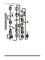
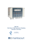
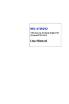
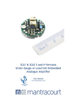
ADW BW Option 1, (no menu selection) (DA=8 (15))
Mantracourt Electronics Limited ADW-BW User Manual
11
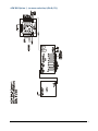
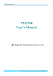
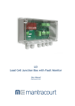
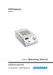
ADW BW Option 2, (with menu selection (DA=24 (31))
12
Mantracourt Electronics Limited ADW-BW User Manual
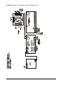
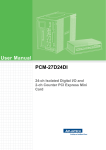
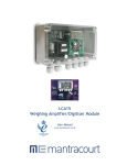
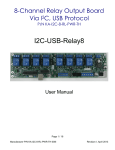
ADW BW Option 3, (no menu selection (DA= 0 (7))
Mantracourt Electronics Limited ADW-BW User Manual
13
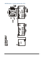
ADW BW Option 4, (with menu selection (DA = 16 (23))
14
Mantracourt Electronics Limited ADW-BW User Manual
Batch Weigher ADW/BW Procedure
Mantracourt Electronics Limited ADW-BW User Manual
15
WARRANTY
All ADW products from Mantracourt Electronics Ltd., ('Mantracourt') are warranted against defective material and workmanship for a period of
(3) three years from the date of dispatch.
If the 'Mantracourt' product you purchase appears to have a defect in material or workmanship or fails during normal use within the period,
please contact your Distributor, who will assist you in resolving the problem. If it is necessary to return the product to 'Mantracourt' please
include a note stating name, company, address, phone number and a detailed description of the problem. Also, please indicate if it is a
warranty repair.
The sender is responsible for shipping charges, freight insurance and proper packaging to prevent breakage in transit.
'Mantracourt' warranty does not apply to defects resulting from action of the buyer such as mishandling, improper interfacing, operation outside
of design limits, improper repair or unauthorised modification.
No other warranties are expressed or implied. 'Mantracourt' specifically disclaims any implied warranties of merchantability or fitness for a
specific purpose. The remedies outlined above are the buyer’s only remedies. 'Mantracourt' will not be liable for direct, indirect, special,
incidental or consequential damages whether based on the contract, tort or other legal theory.
Any corrective maintenance required after the warranty period should be performed by 'Mantracourt' approved personnel only.
ISO 9001
REGISTERED FIRM
C In the interests of continued product development, Mantracourt Electronics Limited reserves the right to alter product specifications
without prior notice.
Code No 517-079
16
Issue 1.7
Mantracourt Electronics Limited ADW-BW User Manual
Date 09.02.09