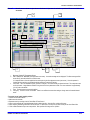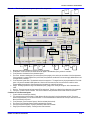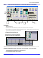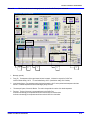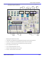
1
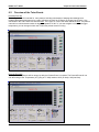
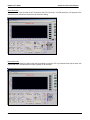
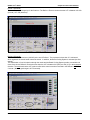
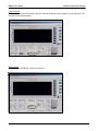
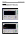
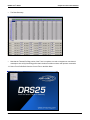
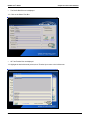
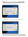
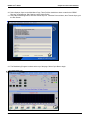
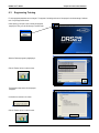
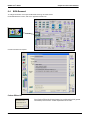
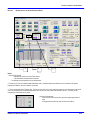
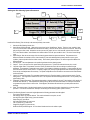
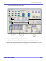
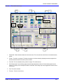
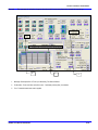
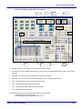
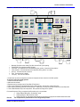
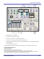
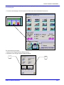
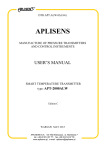
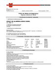
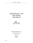
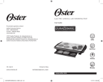
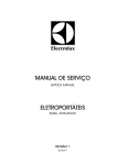
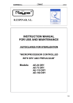
DRS25 User’s Guide
Chapter 6: Profile Tutor Software
Table Of Contents
6
Profile Tutor Guide ...........................................................................................................................................3
6.0
Physical Set Up .........................................................................................................................................................4
6.1
Running Profile Tutor Software .............................................................................................................................5
6.2
Overview of the Tutor Events .................................................................................................................................8
6.3
Engineering Training .............................................................................................................................................22
6.4
BGA Removal .........................................................................................................................................................24
6.5
Site Cleaning ...........................................................................................................................................................44
6.6
Soldering .................................................................................................................................................................59
0025.00.901
6-1
DRS25 User’s Guide
0025.00.901
Chapter 6: Profile Tutor Software
6-2
DRS25 User’s Guide
6
Chapter 6: Profile Tutor Software
Profile Tutor Guide
0025.00.901
6-3
DRS25 User’s Guide
6.0
Chapter 6: Profile Tutor Software
Physical Set Up
Photo left: Board/device with two .003” gauge thermocouple’s slid underneath BGA. One TC attached to top of
device with copper tape, then covered with Kapton tape.
Photo right: TC#1: IR Sensor (Board), TC#2: Top of Device, TC#3: Joint #1, and TC#4: Joint #2.
TC#1: Board
If you purchased the IR Sensor Option, plug it into TC Channel #1. If you do not have the IR Sensor, use Kapton
tape to attach a TC to the board. Position the IR Sensor/TC on an open area of the board 2-3 inches away from
the rework site.
TC#2: Top of Package
Attach a fine gauge TC to the top of the device with copper tape. Cover the copper tape with Kapton tape.
Kapton tape alone can be used but will not provide the same thermal accuracy. Air-Vac uses .003” gauge K-type
TC’s (1-888-TC-OMEGA, Part #5 SRTC-TT-K-40-36). Plug this TC into Channel #2.
TC#3 & #4: Joints
Slide two (2) TC’s underneath the BGA. If possible, slide 1 TC as far into the center of the BGA as possible and
position the second TC near the edge of the device.
Apply Kapton tape to hold the TC’s in place. If desired, x-ray will show the exact positioning of the TC head,
however this is not critical.
Studies have shown that TC’s underneath the BGA that are not in direct contact with a solder joint are typically
within –5 to 0 degrees of the joint temperature. This approach will work in 90% of the cases.
If the standoff height or ball density does not allow a TC to be slid underneath it, a scrap board should be drilled
from the bottom, TC’s installed into the joints and then epoxied in place. If this is not possible, reflow of the
device can be visually observed through the microscope.
The major advantage of this approach is that it is non-destructive yet still highly accurate.
You are now ready to run the Profile Tutor.
0025.00.901
6-4
DRS25 User’s Guide
6.1
Chapter 6: Profile Tutor Software
Running Profile Tutor Software
1. Select Control, Profile Tutor to open the Tutor.
2. Select Tutor Template, Load Tutor Template to access the Master Templates
0025.00.901
6-5
DRS25 User’s Guide
Chapter 6: Profile Tutor Software
3. Master Templates are available for tin-lead and lead-free processes. Highlight the desired template (in this
case the Tin-Lead Master), Thumbs Up Icon to return to Tutor.
4. The Tin-Lead Master is now loaded. Note that the Event Counter shows there are eight events and that event
1 is currently displayed. Use the Up/Down arrow or click on the Event Buttons to view subsequent events.
Event Counter
Up/Down Arrows
Event Buttons
0025.00.901
6-6
DRS25 User’s Guide
Chapter 6: Profile Tutor Software
5. Nozzle Setup - Now that the device has been instrumented with TC’s, install the nozzle for the device. The
nozzle size should match the component size (i.e. N35EZ35EB) for 35mm device). If you do not have the
exact size nozzle for the device, use a nozzle that is larger than the device.
6. Click on the Z-axis power box to depower the Z-axis (box should be unchecked).
Z-axis Power
90
7. Use the X/Y table and the Manual Z-axis knob to position the nozzle directly over the device so that the
nozzle o-ring is lightly touching it. Raise the nozzle .075”. The default nozzle heater flow rate in the template
is 55% (50% of 2.75 scfm, 1.5 scfm). Change the nozzle flow rate based on the nozzle you are using as
shown below:
Nozzle Size (mm)
Less Than 10mm
10 – 15 mm
16 – 26 mm
27 – 30 mm
31 – 34 mm
35 – 40 mm
40+ mm
NMX Nozzles
Nozzle Heater Flow (%)
30%
40%
50%
55%
60%
70%
80%
65%
Be sure to change the flow in all events (use Up/Down arrow to toggle turn events). This flow adjustment
process will be automated in future releases.
0025.00.901
6-7
DRS25 User’s Guide
6.2
Chapter 6: Profile Tutor Software
Overview of the Tutor Events
Preheat (Event #1)
Preheating the board is essential for many reasons including minimization of warpage and allowing lower
localized top heater temperature to be used to reflow the device.If the IR Sensor is plugged into Channel 1, the
checkmark in the TC#1 check box should be blue. If a K-type TC is used, the check should be black. The preheat
event will run until the board reaches its trigger temperature of 90°C. If you want a higher or lower board trigger
temperature, you can change it either now or when the preheat event is running.
Presoak (Event #2)
The top heater temperature will be ramped up after the Preheat Event is complete. The Presoak Event will run
until the Average Joint Temperature (AJT) (Avg of TC 3&4) reaches 139°C (tin lead) / 169 (lead free).
0025.00.901
6-8
DRS25 User’s Guide
Chapter 6: Profile Tutor Software
Soak (Event #3)
The Soak Event is the time that the AJT is between 140-175°C (tin lead) / 170-205 (lead free). The purpose of the
Soak Event is to activate the flux and to help minimize voiding.
Ramp (Event #4)
The top heater is ramped up again during the Ramp Stage to bring the AJT to just below reflow (182 tin lead / 216
typical lead free). The Ramp Event is short, typically 15-20 seconds.
0025.00.901
6-9
DRS25 User’s Guide
Chapter 6: Profile Tutor Software
Reflow 1 (Event #5)
The nozzle heater is ramped up for the final time. The Reflow 1 Event is the time that the AJT is between 183-210
(tin lead) / 217-235 (lead free).
Reflow 2 (Event #6)
The AJT reaches its maximum (210/235) at the end of Reflow 1. The top heater is then shut off. Ambient air
which bypasses the nozzle heater enters the nozzle. In addition, the Board Cooling System is activated (low flow
setting).
The combination of cool air injection through the nozzle and the Board Cooling System provide a controlled cool
down of the device.Reflow 2 records the time when the AJT is between 210 (235) and 183 (217) in the downward
direction. The total time that the AJT is above reflow is the actual event time recorded in the Reflow 1 and Reflow
2 events. (Note: A good target is 45-75 seconds).
0025.00.901
6-10
DRS25 User’s Guide
Chapter 6: Profile Tutor Software
Cool (Event #7)
Cool Air Injection through the nozzle continues, however the Board Cooling System is run at high flow for 45
seconds to cool down the board.
Off (Event #8)
Cool Air Injection and Board Cooling are turned off.
0025.00.901
6-11
DRS25 User’s Guide
Chapter 6: Profile Tutor Software
Other Tutor Notes
Once you adjust the nozzle heater flow rate based on the nozzle you are using (as described previously),
we recommend that you do not change any other parameters prior to the initial run. The default
parameters are based on years of experience and are expected to work “as is” for the vast majority of
applications.
•
The user can change any of the following parameters during an Event:
• Nozzle Heater (Set) Temperature
• Nozzle Heater (Set) Flow
• Bottom Heater (Set) Temperature
• Event Time (Set) (Note: Recommend not changing this)
• Cool Air Injection (On/Off)
• Board Carrier Air (Off, On, Low, On High)
• TC Trigger Temperature (Set)
• Which TC/TC’s control the Event
•
The most frequent user question is - when should they make an adjustment and what parameter(s) should be
adjusted.
The most common reason to make a real-time adjustment is because the actual AJT is not reaching the set
temperature in a reasonable amount of time during an Event.
• Example: Ramp Event
• Trigger Set: 182
• AJT Actual after 20 seconds: 173
• Nozzle Heater Set Temperature: 275
In the above example, the AJT is struggling to achieve the set temperature. Increase the nozzle heater set
temperture by 25 degrees.
Increasing the nozzle heater set temperature to facilitate reaching the trigger set temperature is by far the
most common real-time adjustment.
•
•
•
Important: If the Event 1 Trigger Actual Temperature (IR Sensor) is above 70°°C, do not start the process.
Select the Machine Cooling Tab, activate high flow to cool the board down to at least 70°°. If the Actual
Nozzle Heat Temperature is above 100°°C, select Machine Cooling, Nozzle Cool Down ON.
0025.00.901
6-12
DRS25 User’s Guide
Chapter 6: Profile Tutor Software
Running the Tutor
1. Adjust the Flow Rate based on the Nozzle size as previously described.
2. Verify that the IR Sensor and Nozzle are positioned properly.
3. Click on the Cycle Start Icon to start the Tutor. The Icon will turn Green.
4. Sit back, watch and have a coffee!
The Actual Temperature of all TC’s is digitally displayed.
5. After the process is complete, select Tutor Template, Save As Tutor Results.
0025.00.901
6-13
DRS25 User’s Guide
Chapter 6: Profile Tutor Software
6. Name the new Thermal Process, Thumbs Up, OK.
7. Select Tutor Template, Export Graph to save the graph so it can be printed later along with the Data
Summary for record keeping.
8. Select the Thumbs Up Icon to return to the Main Menu.
IMPORTANT: IF YOU WISH TO RUN ANOTHER THERMAL CYCLE, YOU MUST REOPEN THE MASTER
TEMPLATE (TUTOR TEMPLATE, LOAD TUTOR TEMPLATE).
0025.00.901
6-14
DRS25 User’s Guide
Chapter 6: Profile Tutor Software
9. Select Control, Import Graph Data.
10. Scroll to the end and double click on the file name that you created in Tutor. The graph will be shown.
11. Click on the Graph Data Tab.
0025.00.901
6-15
DRS25 User’s Guide
Chapter 6: Profile Tutor Software
•
The Data Summary:
•
Now that the Thermal Profiling portion of the Tutor is complete, we need to integrate our new thermal
masterpiece into a fully functioning profile that includes all machine motions and operator commands.
12. Select Tutor Profile Build from the Control Tab on the Main Menu.
0025.00.901
6-16
DRS25 User’s Guide
•
Chapter 6: Profile Tutor Software
The Profile Build Screen is displayed.
13. Click on the Select Files Box
•
All Tutor Results files are displayed.
14. Highlight the desired thermal process, then Thumbs Up to return to the build screen.
0025.00.901
6-17
DRS25 User’s Guide
•
Chapter 6: Profile Tutor Software
The Tutor file name and number that you selected is now displayed.
15. If you want to link in a Site Cleaning Profile, toggle the Site Cleaning Radio Button and then click on the
Select File Box.
0025.00.901
6-18
DRS25 User’s Guide
Chapter 6: Profile Tutor Software
16. Highlight the desire Site Cleaning Profile and select Thumbs Up.
17. Name the new Profile in the Long Name Box.
18. Select the Thumbs Up Icon to Save.
19. Select OK twice to Save and return to the Main Menu Page.
0025.00.901
6-19
DRS25 User’s Guide
Chapter 6: Profile Tutor Software
20. Select Options, Open on the Main Menu Page. Three Profiles should have been created in the DRS25
Directory; a Desoldering, Site Cleaning, and a Solder Profile.
21. Select the Desoldering Profile, then the Thumbs Up Icon. Read the Process Notes, then Thumbs Up to go to
the Run Screen.
22. The Desoldering Program is shown at the top of the page. Select Cycle Start to begin.
0025.00.901
6-20
DRS25 User’s Guide
Chapter 6: Profile Tutor Software
23. After removing the device, select the “Load Process Link File” Tab at the top of the screen. Select “Site
Cleaning”.
24. The Site Cleaning Profile is automatically loaded. Cycle Start to begin.
25. After the site is cleaned, select the load “Process Link File” Tab again. Select “Soldering/Desoldering” to run
the Replacement Program.
0025.00.901
6-21
DRS25 User’s Guide
6.3
Chapter 6: Profile Tutor Software
Engineering Training
For most programs parameters are not changed. The purpose of reviewing each event of the program is to educate usage of software
tools. Only changes will be shown.
Under Options, go to Open to view or modify the programs
taught by the Tutor go to the file directory it is stored under.
Select the Removal program by highlighting it.
Click the Thumbs Up icon to exit the screen.
The Application Notes screen for that program
will appear.
Uncheck box to continue to run screen.
Click the Thumbs Up icon to exit the screen.
0025.00.901
6-22
DRS25 User’s Guide
Chapter 6: Profile Tutor Software
The Main Menu screen will appear. Click on
Options/Teach Process Events to get access to the Teach screen.
The Teach Screen will appear.
After review of the Removal program, close the Teach Profile screen by clicking the Thumbs up icon to get to the Main Menu. Reopen the
site cleaning and soldering program be the same above procedure.
0025.00.901
6-23
DRS25 User’s Guide
6.4
Chapter 6: Profile Tutor Software
BGA Removal
To change information on the Open Profile Note Screen go to Teach Screen
Under Miscellaneous Control, click on the Applications Notes icon.
Correct information as required.
Continue Diffuser Idle
Check Continue Diffuser Idle for bottom heater to be on while machine is idle (process
not activated) in the run screen. Set Idle Temperature from run screen.
0025.00.901
6-24
Section 6: Profile Tutor Software
Event 1
Nozzle moves to above board position.
3
2
1
Basics
1. Events (Event Control)
- Indicates the current event of the Teach Screen.
- The total number of events will also be shown.
- The Up/Down arrows will advance to any desired event.
2. Events can be Time or Footswitch based (radio button solid). Footswitch Based event allows event not to advance until operator
presses the footswitch. The time is limited to 10 minutes.
3. Time is programmed in the Time (sec) box. For this event the Time (sec) is zero, when the program is run by the operator, motion will
occur, any process(es) will be activated (temperature, flow, vacuum, etc), then software will advance to event 2. Time (sec) can be
changed up to 600 seconds for any event.
Value can be changed by:
Click in the box next to the function, type value using keyboard and hit
enter.
Use keypad to clear and enter value. Hit enter or thumbs up
DRS25 User Manual 0025.00.901
6- 25
Section 6: Profile Tutor Software
Event 1: Setting the Z-Axis
6
1
4
5
3
2
Basics:
1. Motion (Event Control): If checked, motion will occur in the Teach screen. Z-axis and Vision axis will go the Destination (taught)
position. If unchecked, motion will not occur.
- With the Motion box unchecked events can be advanced with the up/down arrow without motion. For example, to view motion for event
5, advance to event 5 in Events. Check Motion. Machine will home all axis then move to motor positions for event 5.
- If is recommended to check motion prior to running any program.
- Click on Motion box to review motion for the Removal program. Check nozzle height so that it does not hit any top side devices.
2. Z-Move Abs.: Z-Move Absolute indicates the mode of axis motors. The z-axis and vision axis will move to the Dest. (destination)
position.
Position is based from a home position (Z-axis position and vision axis in the retracted position).
3. Pos: Indicates the actual position of the z-axis. Dest: Indicates the Destination position of the z-axis. This is the taught position.
4. Z-Power: Indicates the z-axis motor is powered or not powered. Checked box indicates powered. Clear box indicates not powered.
This allows the operator to manually move the nozzle up or down. The z-axis will move to the Destination position. The vision axis is
always powered.
5. Velocity %/ Accel %: Indicates velocity and acceleration of motion. 1-100% value is available. Decreasing value will slow speed of axis.
Increasing value will increase speed of axis.
6. Blue Graduation Cap icon: Saves settings for the event. No changes will be saved without activating Graduation Cap icon.
To correct (or set) z-axis (nozzle) position
1. Z-Move Abs must be selected.
2. Motion must be checked.
3. Depower motor by removing check in Power Box of Event Control
4. Move z-axis manually with Vertical Movement Knob to desired position. Note the Pos: position will change.
5. Power motor by rechecking Power Box of Event Control. If z-axis motor is not to be on (in other events) do not check Power Box.
6. Click on Blue Graduation Cap to save set position. Dest: position will change to Pos: position.
DRS25 User Manual 0025.00.901
6- 26
Section 6: Profile Tutor Software
Event 1: Lower Heating System
1
1.
The Lower Heating System Controls the temperature of the IR panels. The temperature of the bottom heater panels are set to
200ºC. (Maximum temperature setting: 375ºC)
DRS25 User Manual 0025.00.901
6- 27
Section 6: Profile Tutor Software
Event 2
Operator will position nozzle over device then press the footswitch.
2
1
3
1.
Message: Position Nozzle Over Device. O Ring Should Touch Top Of Device. Any message can be typed in the box to be
displayed to the operator on the Run screen.
2.
Footswitch: Footswitch based event is applied. Software will not advance to the next event until the footswitch is pressed.
At the end of any footswitch event a message “Press Footswitch to Continue” will be displayed to the operator.
3.
Do Not Move: Do Not Move: Z-axis and vision axis motion will not be applied. The destination position (Dest.) is
overridden.
DRS25 User Manual 0025.00.901
6- 28
Section 6: Profile Tutor Software
Event 3
Operator has 5 seconds to Lock the table and position the temperature sensor.
3
5
4
2
1
1. Message: Lock Table and Position IR Temperature Sensor
2.
Time: Time based event is applied.
3.
Time (sec): Five (5) seconds will be applied to the event.
Note: If programmer wishes to allow more time for operator to perform task. Time value can be increased or make this a
Footswitch based event.
4.
The Thermocouple System is activated when a number is applied to a thermocouple channel. The Thermocouple Channels (#1#8) are inactive with a zero (0) as the value. If a K-style Thermocouple is used insert the number one (1) in the box. The number
two “2” is used for the IR Temperature Sensor offset relative to a K-style Thermocouple. In this event channel one is activated
using the IR Temperature Sensor in the “Monitor” mode. In the Run screen the IR temperature Sensor will monitor and display
Channel#1 (board temperature).
5.
Z-Power: The z-axis motor power has been activated. The box is checked.
DRS25 User Manual 0025.00.901
6- 29
Section 6: Profile Tutor Software
Event 4
The nozzle moves away from the component (.075 inches) to allow heat to flow on it and
exhaust away.
5
1
4
3
2
Changing the Relative Motion
1.
Message: (relative move)
2.
Z-Move-REL: Z-Move Relative will set the z-axis mode to make a relative move based on current position.
3.
Dest: The distance of the Relative Move is display in the Destination box. Note: a negative number is up and a positive number
is down (based on home position in the retracted position).
4. To change the Z-Move Relative Position click
on the Table Editor icon and select Nozzle System.
The current event, in this case, event 4 will be highlighted.
Under Nozzle Axis the relative move value will be displayed.
Highlight the Nozzle Axis/ Event 4 box and type in the desired value. Please note negative (minus sign) is required to move the z-axis up.
Click on the Blue Graduation Cap icon to save the values. Check Dest. box to view value.
Conditions for z-axis Relative Move: Z-Move-REL must be checked; Z-Power must be checked; Dest: Value must be indicated.
5. Time: Time based event is applied. Time is set to zero (0) after relative move has occurred.
DRS25 User Manual 0025.00.901
6- 30
Section 6: Profile Tutor Software
Event 5
Board is preheated (based on Profile Tutor results) until set temperature is reached.
6
5
2
1
3
7
4
8
1.
Message: (preheat)
2.
Thermocouple System, Channel #1: Skip. Skip is used to advance “skip to the next event” when a set temperature is reached.
The number two (2) is used in the box for the IR temperature sensor offset.
3.
Thermocouple System, Channel #1: Temp. Temp. is the target temperature setting (for channel #1). In this case the target
temperature setting is 140º C (lead free)(90º C for tin lead). These values can be changed as per thermal profile requirements.
4.
Lower Heating System: Temp. The lower heating system temperature has been increased to enhance bottom/preheating of the
board. Lead Free Solder Setting: 325 ºC Tin Lead Solder Setting: 300 ºC (Maximum temperature setting: 375º)
5.
Time: If sufficient time programmed for preheating, this event can be considered a “Temperature-based” event with
thermocouple activation/temperature being the critical parameter. It is vital that sufficient time be programmed. Change time to
600 seconds if required.
6.
Rate (%): This is the air flow of the upper heater. The air flow is based on the nozzle size (and assembly thermal requirements).
It is based on usage of the Thermal Tutor. (Small Device Profile Tutor Setting: 30%)
7.
Temp (ºC): This is the temperature of the upper heater. It is based on usage of the Profile Tutor.
Lead Free Solder Setting: 125 ºC Tin Lead Solder Setting: 125 ºC
8.
Do Not Move: Z-axis and vision axis motion will not be applied. The destination position (Dest.) is overridden.
DRS25 User Manual 0025.00.901
6- 31
Section 6: Profile Tutor Software
Event 6
Presoak thermal settings (based on Profile Tutor results) are activated.
5
3
1
4
2
1.
Message: (presoak)
2.
Temp (ºC): The temperature of the upper heater has been increased. It is based on usage of the Profile Tutor.
Lead Free Solder Setting: 225 ºC Tin Lead Solder Setting: 225 ºC (Small Device Profile Tutor Setting: 250 ºC )
3.
Time (sec): The time of the event is programmed based on the Profile Tutor.
In reference the average joint temperature would have reached 169ºC for lead free solder.
In reference the average joint temperature would have reached 139ºC for tin lead solder.
4.
Lower Heating System: The temperature setting has been decreased to 200 ºC as the preheat board temperature has been
reached. This setting may be changed for this event and all thermal events (6-10) if board temperature (top and bottom) require
modification. The board temperature should increase slightly during this and subsequent events.
5.
Thermocouple System, Channel #1: Monitor. The mode is changed back to monitor of the board temperature.
DRS25 User Manual 0025.00.901
6- 32
Section 6: Profile Tutor Software
Event 7
Soak thermal settings (based on Profile Tutor results) are activated.
2
1
1. Message: (soak)
2. Time (sec): The time of the event is programmed based on the Thermal Tutor.
In reference, is the time that is the average joint temperature is between 170ºC to 205ºC for lead free solder.
In reference, is the time that is the average joint temperature is between 140ºC to 175ºC for tin lead solder.
Temp (ºC): The temperature of the upper heater is the same for this event. It is based on usage of the Profile Tutor.
Lead Free Solder Setting: 225 ºC Tin Lead Solder Setting: 225 ºC (Small Device Profile Tutor Setting: 250 ºC )
DRS25 User Manual 0025.00.901
6- 33
Section 6: Profile Tutor Software
Event 8
The Ramp thermal settings (based on Profile Tutor results) are activated.
3
1
2
1. Message: (ramp)
2. Temp (ºC): The temperature of the upper heater has been increased. It is based on usage of the Profile Tutor.
Lead Free Solder Setting: 275 ºC Tin Lead Solder Setting: 275 ºC (Small Device Profile Tutor Setting: 300 ºC )
3. Time (sec): The time of the event is programmed based on the Thermal Tutor.
In reference, is the time that is the average joint temperature is between 205ºC to 216ºC for lead free solder.
In reference, is the time that is the average joint temperature is between 175ºC to 182ºC for tin lead solder.
DRS25 User Manual 0025.00.901
6- 34
Section 6: Profile Tutor Software
Event 9
The Reflow 1 thermal settings (based on Profile Tutor results) are activated.
3
1
2
1. Message: (reflow 1)
2. Temp (ºC): The temperature of the upper heater has been increased. It is based on usage of the ProfileTutor.
Lead Free Solder Setting: 295 ºC Tin Lead Solder Setting: 295 ºC (Small Device Profile Tutor Setting: 300 ºC )
3. Time (sec): The time of the event is programmed based on the Thermal Tutor.
In reference, is the time that is the average joint temperature is between 217ºC to 235ºC for lead free solder.
In reference, is the time that is the average joint temperature is between 183ºC to 210ºC for tin lead solder.
DRS25 User Manual 0025.00.901
6- 35
Section 6: Profile Tutor Software
Event 10
Nozzle vacuum is activated.
4
2
1
3
1.
Temp: The Upper Heater Temperature has been set to 300 ºC. This is a set value for the removal templates.
2.
Rate: The Upper Heater Flow Rate has been set to 40%. This is a set value for the removal templates. (Small Device Profile
Tutor Setting: 30%)
3.
Noz Vac.: The nozzle vacuum has been applied.
4.
The Time (sec) is set to 0 seconds. Time is activated after nozzle vacuum and heating changes are applied.
The upper heater temperature, flow rate and time are set values for the removal templates (lead free and tin lead) and are normally
not changed. Certain applications may require modification (match temperature and flow rate of previous event.).
DRS25 User Manual 0025.00.901
6- 36
Section 6: Profile Tutor Software
Event 11
The Vacuum Sensor System is activated. Nozzle Vacuum will be activated and the nozzle will
move down to the component until vacuum (negative pressure) has been sensed by the
system.
1
1.
2
3
4
5
Message: (component removal)
2. Vacuum Sensor Stop: The Vacuum Sensor mode has been applied.
To activate the Vacuum Sensor System:
- Vacuum Sensor Stop: must be checked.
- Noz Vac: Must be checked in this event and in the previous event.
- Z-Power: Must be checked.
It is recommended that “Do Not Move” axis mode be used as the z-axis is already positioned. If Z-Move-ABS is applied the z-axis will
be positioned to the destination (Dest.) position prior to the vacuum sensor activation.
Recommended Motion safety for Vacuum Sensor System:
3. Zero Force: Must be checked. This removes any load/force on the table prior to the Force Placement System activation.
4. Dest: Destination force of the Force Placement System must be set. 125 grams is normal. If vacuum/Vacuum Sensor System
does not activate, the downward pressure will be limited by the Force Placement System (125 grams).
5. Range: Range force of the Force Placement System must be set. 20 grams is normal. This defines the acceptable range to sense.
In this case, the force will be limited to 125 grams +/-20 grams.
DRS25 User Manual 0025.00.901
6- 37
Section 6: Profile Tutor Software
Event 12
The Nozzle will make a Relative Move (-0.200”). This will allow the component to be removed
from the board regardless of board thickness, nozzle position or machine to machine
differences.
1
4
3
2
Relative Motion
1.
Message: (relative move)
2.
Z-Move-REL: Z-Move Relative will set the z-axis mode to make a relative move based on current position.
3. Dest: The distance of the Relative Move is display in the Destination box. Note: a negative number is up and a positive number
is down (based on home position in the retracted position).
4. To change the Z-Move Relative Position click
on the Table Editor icon and select Nozzle System.
The current event, in this case, event 12 will be highlighted.
Under Nozzle Axis the relative move value will be displayed.
Highlight the Nozzle Axis/ Event 12 box and type in the desired value. Please note negative (minus sign) is required to move the z-axis up.
Click on the Blue Graduation Cap icon to save the values. View the destination (Dest.) box to view value.
Conditions for z-axis Relative Move: Z-Move-REL must be checked; Z-Power must be checked; Dest: Value must be indicated.
DRS25 User Manual 0025.00.901
6- 38
Section 6: Profile Tutor Software
Event 13
The nozzle moves up and the vision system extends to component drop off position.
2
3
4
5
6
1
1.
Z-Move-ABS: Z-Move Absolute mode is activated. Motors will move to the destination (Dest.) position of the z-axis and vision
axis.
2.
Z-Axis Dest: Nozzle moves upward to shown destination position. This position will be above the component drop-off position.
The Z-axis motion will go to position prior to the Vision System motion.
3.
Vision Dest: The vision system moves outward to the shown destination position. This position will be for the component drop-off
position.
4.
Temp: Upper heater is turned off. Value is set to 000.
5.
Rate: Upper heater air flow is turned off. Value is set to 000.
6.
Lower Heating System: The temperature setting has been reduced to reduce board and IR panel temperature. This also
promotes establishing initial thermal conditions of the machine.
Note, Standard template assumes site cleaning program to be run immediately after the removal program. If site cleaning
program is not run or increased board cooling is required, activate carrier air for this event and subsequent events. Additional
time may be required in last event (17) to allow for sufficient board and/or machine cooldown.
DRS25 User Manual 0025.00.901
6- 39
Section 6: Profile Tutor Software
Event 14
The z-axis will move down to the drop-off position.
1
1. Z-axis Dest: The nozzle moves to the shown destination position. The z-axis will move down to the drop-off position.
DRS25 User Manual 0025.00.901
6- 40
Section 6: Profile Tutor Software
Event 15
The nozzle vacuum will be turned off and the component is dropped into the drop off tray.
The device/nozzle separation (air pressure) will be turned on for 2 seconds.
5
1
2
4
3
1.
Message: (component drop off)
2.
Do Not Move: Z-axis and vision axis motion will not be applied. The destination position (Dest.) is overridden.
3.
Noz Vac: The nozzle vacuum will be turn off. The box is unchecked.
4.
Device/Nozzle Separation: Air is exhausted out of the nozzle vacuum port. The box is checked.
5.
Time (sec): Time is set to two (2) seconds. Nozzle pressure will be applied for 2 seconds.
Activating the Device/Nozzle Separation (low pressure) will enhance component separation from the nozzle o-ring. After the vacuum
is turned off, the applied pressure will assist in removing the residual vacuum in the system, remove surface tension of the o-ring and
component and help overcome o-ring sticking to the component.
DRS25 User Manual 0025.00.901
6- 41
Section 6: Profile Tutor Software
Event 16
The nozzle retracts, air pressure through the nozzle is turned off and the operator is asked to
remove the BGA.
3
5
1
2
4
1.
Message: Remove BGA
2.
Z-Move –ABS: Z-Move Absolute mode is activated. Motors will move to the Dest: position of the z-axis and vision axis.
3.
Z-Axis Dest: Nozzle moves down to shown destination position. Retracts to home position.
4.
Device/Nozzle Separation: The nozzle pressure (through the vacuum port) is turned off.
5.
Time (sec): Five (5) seconds will be applied to the event to allow the operator to remove the BGA.
Note: If programmer wishes to allow more time for operator to perform task. Time value can be increased or the event can be
changed to be Footswitch based (Footswitch activated to allow time (10 minutes)). The programmer can also change the vision
axis destination to bring the BGA closer to the operator (increase Dest. value).
DRS25 User Manual 0025.00.901
6- 42
Section 6: Profile Tutor Software
Event 17
The Vision axis retracts and the operator is informed that the program is finished.
3
1
2
1.
Message: Process complete.
2.
Vision Dest: The vision system goes to the destination (Dest.) position. Retracts to home position.
3.
Time (sec): The time for the event is 0 seconds.
DRS25 User Manual 0025.00.901
6- 43
Section 6: Profile Tutor Software
6.5
Site Cleaning
Application Notes Screen
To change information on the Application Notes Screen go to Teach Screen
Under Miscellaneous Control, click on the Applications Notes icon.
Correct information as required.
Continue Diffuser Idle
Check Continue Diffuser Idle for bottom heater to be on while machine is idle (process
not activated) in the run screen. Set Idle Temperature from run screen.
DRS25 User Manual 0025.00.901
6- 44
Section 6: Profile Tutor Software
Event 1
Nozzle moves down for operator to remove the EZ nozzle and to install site cleaning nozzle.
Check Motion box to activate motion in the Teach Screen.
3
7
1.
2.
3.
4.
5.
6.
7.
1
5
4
2
6
Message: Remove EZ nozzle, Caution Hot, Install Site Cleaning Nozzle, Unlock Table
Z-Move Abs.: Z-Move Absolute mode is activated. Motors will move to the destination (Dest.) position of the z-axis and vision
axis.
Position is based from a home position (Z-axis position and vision axis in the retracted position).
Z-Power: Z-Power: Indicates the z-axis motor is powered or not powered. Checked box indicates powered. Clear box indicates
not powered. This allows the operator to manually move the nozzle up or down. The z-axis will move to the Destination position.
The vision axis is always powered
Z-axis Pos: Indicates the actual Position of the z-axis.
Z-axis Dest: Indicates the destination position of the z-axis.
Vision axis Pos: Indicates the actual Position of the vision axis.
Vision axis Dest: Indicates the destination position of the vision axis.
Lower Heater System: The temperature of the bottom heater panels are set to 175ºC. It is assumed that the site cleaning
program will be run immediately after the removal program. The temperature can be adjusted if required. Temperature can be
set up to 375 ºC.
Foot: Footswitch based event is applied. Software will not advance to the next event until the footswitch is pressed.
DRS25 User Manual 0025.00.901
6- 45
Section 6: Profile Tutor Software
Event 2
The operator is given the message to focus the microscope with the site cleaning tip at the top
left corner of the site.
1
2
1. Message: Position Nozzle Tip At Back Left Corner of Site. Focus Microscope
This allows the operator to prepare for the viewing of site cleaning operation prior to the nozzle heating the site. This allows for
controlled heating (minimized) of the site.
2.
Clear: The site cleaning system clear box has been activated. The vacuum sensor of the site cleaning system is turned to
determine if the tool is clogged prior to continuing with the procedure. In the Run screen vacuum will go on for a few seconds. If
the tool is clogged, an alarm screen will appear.
DRS25 User Manual 0025.00.901
6- 46
Section 6: Profile Tutor Software
Event 3
Nozzle retracts, the site cleaning clear function is activated and Upper Heater is on for 75 sec.
3
2
9
1.
2.
3.
4.
5.
6.
7.
8.
9.
8
1
5
7
4
6
Message: Apply Flux Paste On Pads. Position Temperature Sensor (nozzle preheat)
Z-Power: The z-axis motor is powered.
Z-axis Dest: The z-axis will move to the destination position (home position). Nozzle retracts upward.
Temp: The temperature of the Upper heater has been set to 400ºC.
Rate: The air flow of the Upper heater has been set to 50%. For tin lead 40%.
Clear: The vacuum sensor (to check if the nozzle is clogged) is turned off.
Vacuum: The site cleaning system nozzle vacuum is turned on.
Time: Time mode of event is activated.
Time (sec): Time is set to 75 seconds.
Note: The purpose of this event is to preheat the nozzle. It is vital that the nozzle be heated so that it does not absorb the thermal
energy while at the site/board position. This will minimize the time the site is heated. In addition, it will insure process control by
establishing consistent initial conditions prior to activating the site cleaning procedure.
Note: The operator can simultaneously flux the site and position the IR temperature sensor. Please note, it is advised that the
operator have flux available for this event. If the site cleaning program is run directly after the removal program, the board is probably
already preheated. Since the next event is board preheat, this event can be short (zero time). The program will move to the next
event in which the nozzle moves to just above the site and start heating. This sequence will not allow the operator to flux the site
without difficulty.
Note: sufficient time is required to preheat the nozzle do not change the time to be less than 75 seconds. Do not change this event to
be footswitch based as various nozzle heating (less than 75 seconds) may not allow efficient heating of the solder. Process issues
and/or pad damage may result.
DRS25 User Manual 0025.00.901
6- 47
Section 6: Profile Tutor Software
Event 4
The IR temperature sensor controls the board length of time of the event based on board temperature.
5
6
3
1
4
5
2
1.
Message: (preheating board)
2.
Do Not Move: Z-axis and vision axis motor motion will not be applied. Note destination position (Dest) is overridden.
3.
Thermocouple System, Channel #1: Skip. Skip is used to advance “skip to the next event” when a set temperature is reached.
The number two (2) is used for the IR temperature sensor offset. Use “1” for thermocouple if machine does not have IR
temperature sensor.
4.
Thermocouple System, Channel #1: Temp. Temp. is the target temperature setting (for channel #1). In this case the target
temperature setting is 125º C (lead free)(100º C for tin lead). These values can be changed as per thermal profile requirements.
5.
Lower Heating System: Temp. The lower heating system temperature has been increased to enhance bottom/preheating of the
board. 325 ºC is the recommended setting (Maximum setting: 375º C).
6.
Temp: 385 ºC. The temperature setting of the upper heater is set for heating of the solder on the pads. (350 ºC for tin lead).
7.
Time: If sufficient time programmed for preheating, this event can be considered a “Temperature-based” event with temperature
being the critical parameter. It is vital that sufficient time be programmed. Change time to 600 seconds if required. It is vital that
the board be preheated prior to site cleaning to minimize heating/time over the pads and reduce board warpage.
DRS25 User Manual 0025.00.901
6- 48
Section 6: Profile Tutor Software
Event 5
The nozzle moves down to just above the solder on the pads.
5
1.
2.
3.
1
3
4
2
Message: (heating initial area)
Z-Move-ABS: Z-Move Absolute indicates the mode of axis motors. The z-axis and vision axis will move to the destination (Dest.)
position.
Z-axis Dest: The z-axis destination position is changed to move the nozzle down to the displayed value. This is a set position on
the template. Adjustments may be required depending on the machine physical conditions-carrier height, board thickness, etc.
The destination position should be set so that the nozzle is approx. 1/8” above the board. The site cleaning nozzle tip must not
touch the board during this event.
To correct (or set) z-axis (nozzle) position
1. Z-Move Abs must be selected.
2. Motion must be checked.
3. Unpower motor by removing check in Power Box of Event Control
4. Move z-axis manually with Vertical Movement Knob to desired position. Note the Pos: position will change.
5. Power motor by rechecking Power Box of Event Control. If z-axis motor is not to be on (in other events) do not check Power Box.
6. Click on Blue Graduation Cap to save set position. Dest: position will change to Pos: position.
Lower Heating System (Temp): The temperature setting for the lower heating system has been lowered to 200 ºC from 325 ºC.
Time (sec): The time of the event is set to 10 seconds. Sufficient time is required to initially heat/melt the solder on the pads
prior to activating the vacuum sensor of the site cleaning system. This time may be increased to insure the solder is melted
before the next event.
This program is based on the large sized site cleaning tip. For medium or small size the flow rate may need to be adjusted. In
addition, the rate may be changed depending on assembly. Increased air flow will increase heat transfer to side (and adjacent areas).
Decreasing air flow will have the opposite effect. Air flow is vital to transfer heat efficiently to the site. Temperature may also be
changed for non-standard applications.
4.
5.
DRS25 User Manual 0025.00.901
6- 49
Section 6: Profile Tutor Software
Event 6
The nozzle tip is positioned to a programmed height based on a vacuum sensor.
2
4
1
1.
Message: (tip height adjustment)
2.
Do Not Move: Z-axis and Vision axis will not move. Destination position (Dest) is overridden.
3.
Site Cleaning System (see next page)
4.
Time (sec): Time is set for 10 seconds to allow for adjustment of the site cleaning system.
3
Note: The time to adjust the tip to the correct distance about the pad is based on the Adjust Pulse (higher value increases motor
speed), Vacuum % (higher value increases distance of tip to pads) and initial height above the pads.
DRS25 User Manual 0025.00.901
6- 50
Section 6: Profile Tutor Software
Setting the Site Cleaning System Parameters
4
2
5
9
3
8
7
6
1
Install the Site Cleaning Tool with the tip to be used and perfectly clean nozzle.
1.
2.
3.
4.
5.
6.
7.
8.
9.
Activate the Site Cleaning Vacuum icon.
Actual Sensor: Will be activated. Observe the vacuum level on the “Actual Sensor” display. This is the “open condition” value.
Let it run 10-20 seconds to settle down and note down the reading. Click the vacuum icon to stop the tool vacuum. Seal the tip
with your finger to form a seal. Activate the vacuum (vacuum icon) again, let it run 10-20 seconds, and note down the value.
This is the “closed condition” value. Subtract the “closed condition” from the “open condition” value. This is the “Sensor Range”
value.
Sensor Range: Sets the vacuum range of the site cleaning system based on system and altitude. This parameter is the
difference between the maximum vacuum, closed condition, (clean tool sealed against the board) and zero vacuum, open
condition, (clean tool-position free from board contact). Enter value by above sequence. The sensor range will be different for
different tip sizes.
Auto Adj Z-Pos: The auto adjustment z-axis positioning activates the site cleaning system.
Vacuum: Turns on the vacuum of the system during the program event. This must be activated in event prior, as well.
Adj.Pulse: Adjust Pulse. This parameter is used to control how far/fast the Z-axis will move during an automatic height
adjustment. This parameter is measured in motor pulses. Typical setting is 008 during site cleaning. A larger number will move
the Z-axis farther from the current position. The setting is higher (018) in the tip height adjustment event to set the tip height fast.
Once set only small adjustments are necessary. The speed is dependent on the time until the next event and the initial distance
set from the board.
Vacuum %: Vacuum Percentage: This parameter determines the tool’s Z-position based on a vacuum sensor sample. Typical
setting is 40%. The range for this number is 0%-100%. 0% will position the tool sealed against the board. For low profile (CSP)
typical setting is 30%.
Clogged(%): Clogged Percentage: This parameter determines a clogged condition for the tool. Typical setting is 20% (usually 1520% lower than Vacuum %). After repeated site cleaning activity, the tool will collect waste solder. At some point the tool will
not generate the proper vacuum to clean a site. If this happens, the software will terminate the cycle and produce an alarm
message.
Clear: The vacuum sensor of the site cleaning system is turned to determine if the tool is clogged prior to continuing with the
procedure. This must be activated in an event prior to activating the site cleaning system. (Done in event 2)
To set the Site Cleaning System for automatic height adjustment the following parameters must be applied:
The z-power must be checked.
Site cleaning vacuum (5) must be checked. This must be activated in event prior, as well.
Auto Adj. Pulse (Auto Adjust Pulse) (4) must be checked.
Sensor Range (3) must be set.
Adj. Pulse (Adjust Pulse) (6) must be set.
Vac % (Vacuum %) (7) must be set.
Clogged % (Clogged %) (8) must be set.
Nozzle should be positioned approx. 1/8” from board. Nozzle must be touch solder on pads.
DRS25 User Manual 0025.00.901
6- 51
Section 6: Profile Tutor Software
Event 7
The auto height adjustment of the site cleaning system is complete and the operator is
instructed to clean the solder from the pads.
2
1
3
1.
Message: Use X Y Wheels To Clean Site (press footswitch when finished)
2.
Foot: The footswitch based event is applied. Software will not advance to the next event until the footswitch is pressed.
3. Site Cleaning System: The site cleaning system will continue to adjust based on the site cleaning system values. The Ad. Pulse
(Adjustment Pulse) value has been changed to 008 to make smaller adjustments. It is assumed that the tip is at the correct
height and that only minor adjustments are required during the cleaning procedure.
DRS25 User Manual 0025.00.901
6- 52
Section 6: Profile Tutor Software
Event 8
The nozzle moves up.
3
2
6
5
1
4
1.
Z-Move-ABS: Z-Move Absolute indicates the mode of axis motors. The z-axis and vision axis will move to the destination (Dest.)
position.
2.
Z-Power: The z-axis is not powered. This allows the operator to site clean manually by adjusting the nozzle tip height with the
machine vertical axis wheel for site touch up in the next event.
3.
Z axis Dest: The z axis destination (Dest.) position is changed. The nozzle moves up.
4.
Site Cleaning System: The site cleaning system automatic height adjustment is turned off. (The site cleaning system vacuum
remains on.) Auto Adj. Z-Pos: Auto Adjust Z-Position is unchecked. Sensor Range, Adj. Pulse, Clogged% and Vacuum% are all
set to zero (0).
5.
Time: Time mode is activated.
6.
Time (sec): The time is set to zero (0).
DRS25 User Manual 0025.00.901
6- 53
Section 6: Profile Tutor Software
Event 9
The operator is asked to inspect the site and if necessary lower the nozzle for touch up.
3
1
1.
Message: Clean/Inspect Site. If Touch Up Is Necessary, Flux Site and Reheat
2.
Do Not Move: Z-axis and Vision axis will not move. Destination position (Dest) is overridden.
3.
Foot: Footswitch based event mode is applied.
DRS25 User Manual 0025.00.901
2
6- 54
Section 6: Profile Tutor Software
Event 10
The nozzle moves up. The upper heater system temperature is turned down, lower heating
system is turned off and the lower heater system cooling air is turned on.
2
9
8
4
5
3
1
7
6
1.
Message: (board and machine cooldown)
2.
Z-Power: The z-axis motor is powered.
3.
Z-Move-ABS: Z-Move Absolute indicates the mode of axis motors. The z-axis and vision axis will move to the destination (Dest.)
position.
4.
Z axis Dest: The z axis destination (Dest.) position is changed. The nozzle moves up.
5.
Temp: Temperature of the upper heater is changed to 100c (from 385c-lead free, 350c-tin lead). This lower temperature is set
to reestablish initial thermal conditions of the machine.
6.
Lower Heating System (Temp): The temperature setting is set to zero (0) to reestablish initial thermal conditions of the machine.
7.
Carrier Air: The board cooling system air is activated (low flow-black check in box).
8.
Time: The time mode is activated.
9. Time (sec): The time is set to 60 seconds. Time may be increased to further cool the board and/or machine or decreased if site
cleaning will be performed on boards in succession.
DRS25 User Manual 0025.00.901
6- 55
Section 6: Profile Tutor Software
Event 11
Upper heater and lower heating system carrier air are turned off.
3
7
1
5
1.
Message: Clean Site and Inspect
2.
Do Not Move: Z-axis and Vision axis will not move. Destination position (Dest) is overridden.
3.
Rate: The upper heater air is turned off. Set to zero (000)
4.
Temp: The upper heater temperature is turned off. Set to zero (000)
5.
Carrier Air: The carrier air is turned off. (Box unchecked.)
6.
Vacuum: The site cleaning vacuum is turned off. (Box unchecked.)
7.
Foot: Footswitch based event mode is applied.
DRS25 User Manual 0025.00.901
4
2
6
6- 56
Section 6: Profile Tutor Software
Event 12
The nozzle is positioned and the operator is asked to remove the nozzle.
1
3
2
1.
Message: Remove Site Clean Nozzle and Reinstall Nozzle
2.
Z-Move-ABS: Z-Move Absolute indicates the mode of axis motors. The z-axis and vision axis will move to the destination (Dest.)
position.
3.
Z-axis Dest: The z axis desitnation (Dest.) position is set to 3.00”. This position should allow the operator to remove the nozzle.
The Z-power can be unchecked (depowered) if desired to allow the z-axis free to move for the operator (without depowering on
run screen).
DRS25 User Manual 0025.00.901
6- 57
Section 6: Profile Tutor Software
Event 13
The nozzle moves to the home position.
3
2
1.
Z-axis Dest: The z axis destination (Dest.) position is set to zero (0)(home position).
2.
Time: The time based event mode is activated.
3.
Time (sec): Time is set to zero (0)
DRS25 User Manual 0025.00.901
1
6- 58
Section 6: Profile Tutor Software
6.6
Soldering
Applications Notes Screen
To change information on the Open Profile Note Screen, go to Teach Screen.
Under Miscellaneous Control, click on the Applications Notes icon.
Correct information as required.
Continue Diffuser Idle
Check Continue Diffuser Idle for bottom heater to
be on in the run screen and the process is not activated.
Set Idle on run screen.
DRS25 User Manual 0025.00.901
6- 59
Section 6: Profile Tutor Software
Event 1
Operator is asked to check the assembly board temperature.
Check Motion box to activate motion in the Teach Screen.
4
3
3
2
1
1.
Message: Check Board Temp. If Above 70 (TL/100(lead free), Stop Process and Cool Bd.
It is important to have the same initial assembly conditions as when the profile tutor created the heating event parameters. This
will manifest process repeatability. If the board temperature is above 100c the software will automatically advance (time of event
will be zero) from the board preheat event to the next heating event. This will result in “cold” solder joints since the preheat event
when created by the profile tutor applied heat from the upper heater for some designated time.
1.
Z-Move-ABS: The z-move absolute mode is activated. Axis motors will move to the destination (Dest.) position of the z-axis and
vision axis.
2.
Z axis Dest: The nozzle moves to the destination (Dest.) position. Home position.
Vision Dest: The vision system moves to the destination (Dest.) position. Retracted position.
3.
Foot: Footswitch based event is applied. Software will not advance to the next event until the footswitch is pressed.
4.
Monitor: The Thermocouple System is activated when a number is applied to a channel. The Thermocouple Channels (#1- #8)
are inactive with a zero (0) as the value. If a K-style Thermocouple is used insert the number one (1) in the box. The number two
“2” is used for the IR Temperature Sensor offset relative to a K-style Thermocouple. Channel one is activated using the IR
Temperature Sensor in the “Monitor” mode. In the Run screen the IR temperature Sensor will display (only) (board temperature).
DRS25 User Manual 0025.00.901
6- 60
Section 6: Profile Tutor Software
Event 2
Operator is asked to move IR temperature sensor out of nozzle and vision axis range.
3
7
6
1
4
5
2
1.
Message: Move IR Temperature Sensor Away From Nozzle and Vision (stabilizing heater)
2.
Do Not Move: Z-axis and vision axis motion will not be applied. The destination (Dest.) positions are overridden.
3.
Rate: The air flow of the upper heater is set to 60%
4.
Temp: The temperature of the upper heater is set to 100c.
5.
Lower Heater System (L, M, R-Temp): The lower heating system has been activated. The temperature is set to 100c.
6.
Time: Time based event is applied.
7.
Time (sec): Time is set to 30 seconds. Time may be adjusted if required. Longer length of time will improve machine
stabilization, but increase process time.
DRS25 User Manual 0025.00.901
6- 61
Section 6: Profile Tutor Software
Event 3
The nozzle moves to the home position. The vision system moves to the component pick up
position. The upper heating system is turned off.
4
8
1
7
6
3
2
5
1.
Message: Place Device Into Loading Tray With Vacuum Probe (check polarity).
2.
Z-Move-ABS: The z-move absolute mode is activated. Axis motors will move to the destination (Dest.) position of the z-axis and
vision axis.
3.
Z axis Dest: The nozzle moves to the destination (Dest.) position. Home position.
4.
Vision Dest: The vision system moves to the destination (Dest.) position. Component pickup position.
5.
Probe: The vacuum probe vacuum is turned on. Boxed is checked.
6.
Rate: The upper heater system air flow is turned off (000)
7.
Temp: The upper heater system temperature is set to zero (000)
8.
Foot: Footswitch based event is applied.
If Universal Component Tool (or component specific insertion tool) is not purchased:
- Change vision axis Dest to home position.
- Change message to “Place device centered under nozzle”.
DRS25 User Manual 0025.00.901
6- 62
Section 6: Profile Tutor Software
Event 4
Nozzle moves down (to component pick up position). Nozzle vacuum is turned on.
4
7
1.
2.
3.
4.
5.
6.
7.
6
3
1
2
5
Message: Place Device Into Loading Tray With Vacuum Probe. (check polarity)
Z-Move-ABS: Z-move absolute mode is activated.
Z axis Dest: The nozzle will move to the destination (Dest.) position. Component pickup position.*
Vision axis Dest: The nozzle will move to the destination (Dest.) position. (no motion)
Noz Vac: The nozzle vacuum is turned on.
Time: Time mode event is applied.
Time (sec): Time is set to 2 seconds.
* If nozzle does not reach the component or pushes the component to hard, correct the z-axis Dest. position.
To correct (or set) z-axis (nozzle) position
1. Z-Move Abs must be selected.
2. Motion must be checked.
3. Depower motor by removing check in Power Box of Event Control
4. Move z-axis manually with Vertical Movement Knob to desired position. Note the Pos: position will change.
5. Power motor by rechecking Power Box of Event Control. If z-axis motor is not to be on (in other events) do not check Power Box.
6. Click on Blue Graduation Cap to save set position. Dest: position will change to Pos: position.
If Universal Component Tool (or component specific insertion tool) is not purchased:
a. Change Z-Move-ABS mode to “Do Not Move” mode.
b. Change message to “Move hand from nozzle”
c. Change Time (sec) to 10 seconds to allow operator to move hand or change time to footswitch based event mode.
Event 5
The component is positioned to vision alignment position.
DRS25 User Manual 0025.00.901
6- 63
Section 6: Profile Tutor Software
4
6
1
3
2
5
1.
Message: Align Device, Lock Board Carrier.
2.
Z Move-ABS: Z-move absolute mode is activated.
3.
Z axis Dest: The nozzle will move to the destination (Dest.) position.*
4.
Vision axis Dest: The vision system will move to the destination (Dest.) position.
5.
Vision Lights: Activates lights (LEDS) of vision system. Independent lighting intensity of the component leads and assembly
pads are adjustable.**
6.
Foot: Footswitch based event is applied.
* It is important that the z-axis position be correct to allow the component leads to be in focus while the board pads are in focus.
To correct (or set) z-axis (nozzle) position
1. Z-Move Abs must be selected.
2. Motion must be checked.
3. Depower motor by removing check in Power Box of Event Control
4. Move z-axis manually with Vertical Movement Knob to desired position. Note the Pos: position will change.
5. Power motor by rechecking Power Box of Event Control. If z-axis motor is not to be on (in other events) do not check Power Box.
6. Click on Blue Graduation Cap to save set position. Dest: position will change to Pos: position.
DRS25 User Manual 0025.00.901
6- 64
Section 6: Profile Tutor Software
**It is important to provide the correct lighting to provide the correct lighting intensity for maximum lighting contrast of the component leads
to the assembly pads.
1. To set and/or activate lighting of the vision system in the Teach screen click on the Hardware-Processes icon.
The Limit Control Screen will appear.
1. Adjust top vision LED (light intensity) by sliding the slide bar.
2. Adjust bottom vision LED (light intensity) by sliding the slide bar.
1
DRS25 User Manual 0025.00.901
2
6- 65
Section 6: Profile Tutor Software
Event 6
The vision system retracts. Operator is asked to flux site, if required.
3
4
6
1
5
1.
Message: Flux Site Unless Solder Paste Has Been Applied.
2.
Z Move-ABS: Z-move absolute will move to the destination (Dest.) position of the z-axis and vision system axis.
3.
Z axis Dest: The nozzle will move to the destination (Dest.) position.
4.
Vision axis Dest: The vision system will move to the destination (Dest.) position. Retract to the home position.
5.
Vision Lights: The lights of the vision system are turned off.
6.
Foot: Footswitch based event is applied.
DRS25 User Manual 0025.00.901
2
6- 66
Section 6: Profile Tutor Software
Event 7
Nozzle moves down to just above the board. Operator is asked to position IR sensor within 10
seconds.
4
5
1.
2.
3.
4.
5.
3
1
2
Message: Position IR Temperature Sensor
Alert: HANDS OFF MACHINE (force placement next event). A second message can be displayed. The Alert message will be
shown five (5) seconds before the end of the event.
It is important that no force be applied to the machine during the force placement event (next event). Once the operator is
familiar with the machine, ten seconds should be sufficient to move the IR sensor.
Z axis Dest: The z axis destination (Dest.) position is changed. The nozzle moves just above the board. The component must
not hit the board. A large distance will take a long time for the force placement to finish. The correct distance is approximately
1/16-1/8” above the board.*
Time: The time based event mode is applied.
Time (sec): The time is set for 10 seconds. If time is not sufficient increase time setting or change event to footswitch based
mode.
*To correct (or set) z-axis (nozzle) position
1. Z-Move Abs must be selected.
2. Motion must be checked.
3. Depower motor by removing check in Power Box of Event Control
4. Move z-axis manually with Vertical Movement Knob to desired position. Note the Pos: position will change.
5. Power motor by rechecking Power Box of Event Control. If z-axis motor is not to be on (in other events) do not check Power Box.
6. Click on Blue Graduation Cap to save set position. Dest: position will change to Pos: position.
DRS25 User Manual 0025.00.901
6- 67
Section 6: Profile Tutor Software
Event 8
The force placement system places the component.
8
1
4
7
2
3
5
6
1.
2.
3.
4.
Message: Keep Hands Off Machine During Event. (force placement)
Do Not Move: Z-axis and vision axis motion will not be applied. The destination (Dest.) position is overridden.
Force Placement: Activates the force placement system.
Zero Force: Activates resetting (zero) the current (actual) force (weight) on the carrier prior to activation of the force placement.
If the component is in contact (applies force) to the board, the system will consider this to be zero and apply additional force until
the target valued is reached.
5. Force Placement System Dest: The destination value is the target force. The target force may be programmed from 75 to 2000
grams. 125 grams is standard for BGA placement. After the zero force tares the load, the z-axis will move until the carrier
system registers the target force. Once the target force is reached, the z-axis will stop motion.
6. Range: The Range provide the range of the destination (Dest.) (target) force. Usually set to approx. 20% of destination force
value.
7. Noz Vac: The nozzle vacuum has been turned off. Box unchecked. This will occur after the force placement of the component.
8. Time (sec): The time is set for 2 seconds. This will occur after the force placement and the nozzle vacuum is turned off.
Conditions for Force Placement System:
1. Z-power: Must be activated (box checked).
2. The component must not hit the board. A large distance will take a long time for the force placement to finish. The correct
distance is approximately 1/16-1/8” above the board. It is recommended that the distance be set in the prior event and Do Not
Move be the mode for the z-axis.
3. Force Placement (Force Placement System): Must be activated (box checked)
4. Zero Force (Force Placement System): Must be activated (box checked)
5. Dest (Force Placement System): The Dest. (destination) value must be entered.
6. Range (Force Placement System): The Range value must be entered.
DRS25 User Manual 0025.00.901
6- 68
Section 6: Profile Tutor Software
Event 9
Air is exhausted out of the nozzle vacuum port.
3
1
4
1.
Message: (nozzle vacuum off, nozzle pressure on)
2.
Device/Nozzle Separation: Air pressure to nozzle vacuum port is activated.
3.
Time (sec): The time is set for 2 seconds. (Device/Nozzle separation will occur for 2 seconds.)
4.
Force Placement System: Is turned off. All boxes are unchecked.
DRS25 User Manual 0025.00.901
2
6- 69
Section 6: Profile Tutor Software
Event 10
The nozzle moves away from the component (.075 inches) to allow heat to flow on it and exhaust away.
4
6
1
3
2
5
Relative Motion
1.
Message: (relative move)
2.
Z-Move-REL: Z-Move Relative will set the z-axis mode to make a relative move based on current position.
3.
Dest: The distance of the Relative Move is display in the Destination box. Note: a negative number is up and a positive number
is down (based on home position in the retracted position).
4. To change the Z-Move Relative Position click
on the Table Editor icon and select Nozzle System.
The current event, in this case, event 10 will be highlighted.
Under Nozzle Axis the relative move value will be displayed.
Highlight the Nozzle Axis/ Event 10 box and type in the desired value. Please note negative (minus sign) is required to move the z-axis up.
Click on the Blue Graduation Cap icon to save the values.
Conditions for z-axis Relative Move: Z-Move-REL must be checked; Z-Power must be checked; Dest: Value must be indicated.
5.
6.
Device/Nozzle Separation: Exhausted air from the nozzle should remain on.
Time: Time based event is applied. Time is set to zero (0).
DRS25 User Manual 0025.00.901
6- 70
Section 6: Profile Tutor Software
Event 11
Board is preheated (based on the Profile Tutor) until set temperature is reached.
6
6
3
1
4
5
7
2
1.
Message: (preheat)
2.
Do Not Move: Z-axis and vision axis motion will not be applied. The destination position (Dest.) is overridden.
3.
Thermocouple System, Channel #1: Skip. Skip is used to advance “skip to the next event” when a set temperature is reached.
The number two (2) is used for the IR temperature sensor offset.
4.
Thermocouple System, Channel #1: Temp. Temp. is the target temperature setting (for channel #1). In this case the target
temperature setting is 140º C (lead free)(90º C for tin lead). These values can be changed as per thermal profile requirements.
5.
Lower Heating System: Temp. The lower heating system temperature has been increased to enhance bottom/preheating of the
board. (Maximum Temperature Setting: 375º C)
6.
Time: If sufficient time programmed for preheating, this event can be considered a “Temperature-based” event with temperature
being the critical parameter. It is vital that sufficient time be programmed.
7.
Rate (%): This is the air flow of the upper heater. The air flow is based on the nozzle size (and assembly thermal requirements).
It is based on usage of the Thermal Tutor. (Small device rate: 30% default)
8.
Temp (ºC): This is the temperature of the upper heater. It is based on usage of the Profile Tutor.
Lead Free Solder Setting: 125 ºC Tin Lead Solder Setting: 125 ºC
DRS25 User Manual 0025.00.901
6- 71
Section 6: Profile Tutor Software
Event 12
The Presoak thermal settings (based on the Profile Tutor) are activated.
5
4
1
3
2
1.
Message: (presoak)
2.
Temp (ºC): The temperature of the upper heater has been increased. It is based on usage of the Profile Tutor.
Lead Free Solder Setting: 225 ºC Tin Lead Solder Setting: 225 ºC. (Small device setting: 250 ºC default)
3.
Lower Heating System: The temperature setting has been decreased to 200 ºC as the preheat board temperature has been
reached. The board temperature should increase slightly during this event.
4.
Thermocouple System, Channel #1: Monitor. The mode is changed back to monitor of the board temperature.
5.
Time (sec): The time of the event is programmed based on the Profile Tutor.
In reference the average joint temperature would have reached 169ºC for lead free solder.
In reference the average joint temperature would have reached 139ºC for tin lead solder.
DRS25 User Manual 0025.00.901
6- 72
Section 6: Profile Tutor Software
Event 13
The Soak thermal settings (based on the Profile Tutor) are activated.
3
1
2
1. Message: (soak)
2. Temp (ºC): The temperature of the upper heater has been increased. It is based on usage of the Profile Tutor.
Lead Free Solder Setting: 225 ºC Tin Lead Solder Setting: 225 ºC . (Small device setting: 250 ºC default)
3. Time (sec): The time of the event is programmed based on the Profile Tutor.
In reference, is the time that is the average joint temperature is between 170ºC to 205ºC for lead free solder.
In reference, is the time that is the average joint temperature is between 140ºC to 175ºC for tin lead solder.
DRS25 User Manual 0025.00.901
6- 73
Section 6: Profile Tutor Software
Event 14
The Ramp thermal settings (based on the Profile Tutor) are activated.
3
1
2
1. Message: Ramp
2. Temp (ºC): The temperature of the upper heater has been increased. It is based on usage of the Profile Tutor.
Lead Free Solder Setting: 275 ºC Tin Lead Solder Setting: 275 ºC (Small device setting: 300 ºC default)
3. Time (sec): The time of the event is programmed based on the Profile Tutor.
In reference, is the time that is the average joint temperature is between 205ºC to 216ºC for lead free solder.
In reference, is the time that is the average joint temperature is between 175ºC to 182ºC for tin lead solder.
DRS25 User Manual 0025.00.901
6- 74
Section 6: Profile Tutor Software
Event 15
The Reflow 1 thermal settings (based on the Profile Tutor) are activated.
3
1
2
1. Message: (reflow 1)
2. Temp (ºC): The temperature of the upper heater has been increased. It is based on usage of the Profile Tutor.
Lead Free Solder Setting: 295 ºC Tin Lead Solder Setting: 295 ºC (Small device setting: 340 ºC default)
3. Time (sec): The time of the event is programmed based on the Profile Tutor.
In reference, is the time that is the average joint temperature is between 217ºC to 235ºC for lead free solder.
In reference, is the time that is the average joint temperature is between 183ºC to 210ºC for tin lead solder.
DRS25 User Manual 0025.00.901
6- 75
Section 6: Profile Tutor Software
Event 16
The Reflow 2 thermal settings (based on the Profile Tutor) are activated.
5
1
4
3
2
1.
Message: (reflow 2)
2.
Temp (ºC): The temperature of the upper heater is turned off. It is based on usage of the Thermal Tutor.
3.
Cool Air: Nozzle cool air injection provides ambient air which bypasses the nozzle heater enters the nozzle at flow rate of
previous events.
4.
Carrier Air: The board cooling system is activated (low flow setting—black check in box).
5.
Time (sec): The time of the event is programmed based on the Thermal Tutor.
In reference, is the time that is the average joint temperature is between 235ºC to 217ºC for lead free solder.
In reference, is the time that is the average joint temperature is between 210ºC to 183ºC for tin lead solder.
DRS25 User Manual 0025.00.901
6- 76
Section 6: Profile Tutor Software
Event 17
The board carrier cooling system air flow is increased for 45 seconds.
3
1
2
1.
Message: (cool down)
2.
Carrier Air: The board cooling system is set to run at high air flow. Blue check in box.
3.
Time (sec): The time is set for 45 seconds. Additional time may be required for high mass assemblies.
DRS25 User Manual 0025.00.901
6- 77
Section 6: Profile Tutor Software
Event 18
The board cooling system and upper heater cool air injection are shut off.
3
1
1.
Carrier Air: The board cooling system is turned off.
2.
Cool Air: The nozzle cool air injection is turned off.
3.
Time (sec): The time of the event is set to one (1) second (after the carrier air and cool air are turned off).
DRS25 User Manual 0025.00.901
2
6- 78
Section 6: Profile Tutor Software
Event 19
The Nozzle moves up, the upper heater is turned on at 100c and the board cooling system is
activated (low flow) for 30 seconds.
4
8
5
3
1
7
1.
Message: (process complete. heater cool down)
2.
Z Move-ABS: Z-move absolute will move to the destination (Dest.) position of the z-axis and vision system axis.
3.
Z axis Dest: The nozzle will move to the destination (Dest.) position. Retract to the home position.
4.
Vision axis Dest: The vision system will move to the destination (Dest.) position (home position).
5.
Rate: The upper heater air flow is set to 50%.
6.
Temp: The upper heater temperature is set to 100c.
7.
Carrier Air: The board cooling system is set to low air flow.
8.
Time (sec): The time of the event is set to 30 seconds.
DRS25 User Manual 0025.00.901
6
2
6- 79
Section 6: Profile Tutor Software
DRS25 User Manual 0025.00.901
6- 80