1
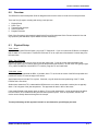
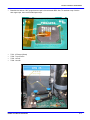
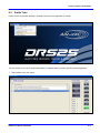
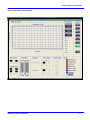
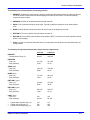
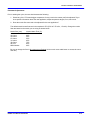
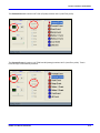
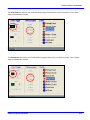
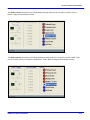
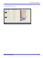
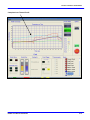
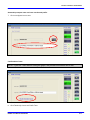
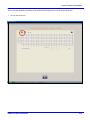
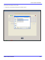
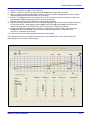
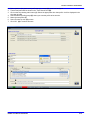
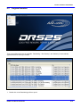
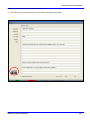
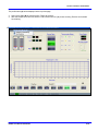
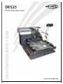
DRS25
PROCESS DEVELOPMENT GUIDE
www.air-vac-eng.com
Section 6: Profile Tutor Software
Table Of Contents
6
Process Development Guide...........................................................................................................................3
6.0
Overview ...................................................................................................................................................................4
6.1
Physical Setup...........................................................................................................................................................4
6.2
Profile Tutor .............................................................................................................................................................6
6.3
Thermal Profile Analysis .......................................................................................................................................18
6.4
Auto Profile Build...................................................................................................................................................22
6.5
Program Execution ................................................................................................................................................24
DRS25 User Manual 0025.00.901
6- 1
Section 6: Profile Tutor Software
DRS25 User Manual 0025.00.901
6- 2
Section 6: Profile Tutor Software
6
Process Development Guide
DRS25 User Manual 0025.00.901
6- 3
Section 6: Profile Tutor Software
6.0
Overview
The DRS25 Process Development Guide is designed to allow novice users to create and run new processes.
There are five (5) steps to creating and running a new process:
1.
2.
3.
4.
5.
Physical Setup
Profile Tutor
Thermal Profile Analysis
Auto Profile Build
Program Execution
Each of the five steps is documented in detail in this Process Development Guide. Please contact Air-Vac with
any questions (203-888-9900; request DRS25 Process Assistance).
6.1
Physical Setup
TC#1: Board
If you purchased the IR Sensor Option, plug it into TC Channel #1. If you do not have the IR Sensor, use Kapton
tape to attach a TC to the board. Position the IR Sensor/TC on an open area of the board 2-3 inches away from
the rework site.
TC#2: Top of Package
Attach a fine gauge TC to the top of the device with copper tape. Cover the copper tape with Kapton tape.
Kapton tape alone can be used but will not provide the same thermal accuracy. Air-Vac uses .003” gauge K-type
TC’s (1-888-TC-OMEGA, Part #5 SRTC-TT-K-40-36). Plug this TC into Channel #2.
TC#3 & #4: Joints
Slide two (2) TC’s underneath the BGA. If possible, slide 1 TC as far into the center of the BGA as possible and
position the second TC near the edge of the device.
Apply Kapton tape to hold the TC’s in place. If desired, x-ray will show the exact positioning of the TC head,
however this is not critical.
Studies have shown that TC’s underneath the BGA that are not in direct contact with a solder joint are typically
within –5 to 0 degrees of the joint temperature. This approach will work in 90% of the cases.
If the standoff height or ball density does not allow a TC to be slid underneath it, a scrap board should be drilled
from the bottom, TC’s installed into the joints and then epoxied in place. If this is not possible, reflow of the
device can be visually observed through the microscope.
The major advantage of this approach is that it is non-destructive yet still highly accurate.
DRS25 User Manual 0025.00.901
6- 4
Section 6: Profile Tutor Software
•
Board/device with two .003” gauge thermocouple’s slid underneath BGA. One TC attached to top of device
with copper tape, then covered with Kapton tape.
•
•
•
•
TC#1:
TC#2:
TC#3:
TC#4:
IR Sensor (Board)
Top of Device
Joint #1
Joint #2.
DRS25 User Manual 0025.00.901
6- 5
Section 6: Profile Tutor Software
6.2
Profile Tutor
Profile Tutor is the process whereby a Thermal Profile for a new application is created.
The user selects one of the Thermal Profile Master Templates that most closely matches the new application.
1. Select (double click) the master.
DRS25 User Manual 0025.00.901
6- 6
Section 6: Profile Tutor Software
Profile Tutor screen shown (blank).
DRS25 User Manual 0025.00.901
6- 7
Section 6: Profile Tutor Software
The master profile name will be displayed at the top of the page.
All master profiles typically have seven (7) stages (Events): Preheat,
Presoak, Soak, Ramp, Reflow 1, Reflow 2, and Cool.
2. Under OPTIONS, click to depower Z-Axis (box turns red).
3. Position nozzle over component.
4. Lightly touch component with nozzle o-ring, then retract approximately
.100”.
5. Click to repower Z-Axis (box turns green).
DRS25 User Manual 0025.00.901
6- 8
Section 6: Profile Tutor Software
The following is a brief description of each stage (Event):
1. PREHEAT: Preheats the entire board to minimize the thermal differential between the reflow site and the
rest of the board. Preheat minimizes board warpage and reduces the amount of component heating
required to achieve reflow.
2. PRESOAK: Presoak is the period between preheat and soak.
3. SOAK: Flux is activated during the soak stage. Typically, significant voiding will occur without proper
soak.
4. RAMP: Quickly takes the solder joints from the end of soak to the beginning of reflow.
5. REFLOW 1: Time over liquidus until the heaters are shut off.
6. REFLOW 2: Time until the joints fall back below liquidus. NOTE: Total time over reflow equals the total of
Reflow 1 and 2 stages.
7. COOL: Cools the component and board down to a temperature that allows the reworked assembly to be
safely handled.
The following are typical time/temperature targets for each stage (Event):
Tin/Lead
Lead-Free
PREHEAT
- Topside Board Temp (°C)
90-100
140-150
PRESOAK
- Temp (°C)
- Time (seconds)
101-139
15-30
141-169
15-30
SOAK (joint)
- Temp (°C)
- Time (seconds)
140-170
45-60
170-200
45-60
RAMP (joint)
- Temp (°C)
- Time (seconds)
171-182
15-30
201-216
15-30
REFLOW 1 (joint)
- Temp (°C)
- Time (seconds)
183-205
30-45
217-235
30-45
REFLOW 2 (joint)
- Temp (°C)
- Time (seconds)
205-183
15-30
235-217
15-30
COOL (joint)
- Temp (°C)
- Time (seconds)
100
60-180
150
60-180
•
•
•
183
210
250
217
235
260
Typical solder liquidus temp (°C)
Typical max joint temp (°C)
Typical max package temp (°C)
DRS25 User Manual 0025.00.901
6- 9
Section 6: Profile Tutor Software
Parameter Adjustments
Prior to starting the cycle, the user should assess the following:
1. Should any of the T/C-based trigger temperature for any event in the master profile be adjusted? If you
know specific information about the new application, adjust temperature targets, if not, leave as is.
2. Does the nozzle flow rate need to be adjusted for the new application?
The default nozzle heater flow rate in the template is 55% (50% of 2.75 scfm, 1.5 scfm). Change the nozzle
flow rate based on the nozzle you are using as shown below.
Nozzle Size (mm)
Less than 10mm
10-15mm
16-26mm
27-30mm
31-34mm
35-40mm
40+ mm
NMX Nozzles
Nozzle Heater Flow (%)
30%
40%
50%
55%
65%
75%
85%
60%
Be sure to change the flow in all events except Preheat (click on each event radio button to access the event
flow rate).
DRS25 User Manual 0025.00.901
6- 10
Section 6: Profile Tutor Software
6. Click on the Cycle Start icon (A) to start the Thermal Profiling process.
•
•
•
•
If any of the T/C’s are above 60C, the board cooling system and nozzle cool down will come on
automatically and remain on until all T/C’s are below 60C.
The graph will begin to plot temperatures for the top heater, bottom heater and all thermocouples. T/C
temperature is also digitally displayed (B).
During all events except Preheat Nozzle Temperature (recommended) or flow can be adjusted on-the-fly
if required to help achieve the event trigger target or the desired event time.
If an on-the-fly adjustment is made, an additional event will be automatically creqted and displayed.
B
A
DRS25 User Manual 0025.00.901
6- 11
Section 6: Profile Tutor Software
The Preheat Event will continue until T/C#1 (IR probe) reaches 140°C (Lead-Free profile).
The Presoak Event will continue until T/C#3 and #4 (average) reaches 169°C (Lead-Free profile). Time in
Presoak stage is automatically recorded.
DRS25 User Manual 0025.00.901
6- 12
Section 6: Profile Tutor Software
The Soak Event will continue until T/C#3 and #4 (average) reaches 200°C (Lead-Free profile). Time in Soak
stage is automatically recorded.
200
The Ramp Event will continue until T/C#3 and #4 (average) reaches 216°C (Lead-Free profile). Time in Ramp
stage is automatically recorded.
DRS25 User Manual 0025.00.901
6- 13
Section 6: Profile Tutor Software
The Reflow 1 Event will continue until T/C#3 and #4 (average) reaches 235°C (Lead-Free profile). Time in
Reflow 1 stage is automatically recorded.
The Reflow 2 Event will continue until T/C#3 and #4 drop down below 217°C (Lead-Free profile). NOTE: Total
time over reflow is the sum of Reflow 1 and Reflow 2. Time in Reflow 2 stage is automatically recorded.
DRS25 User Manual 0025.00.901
6- 14
Section 6: Profile Tutor Software
The Cool Down Event – 45 seconds
DRS25 User Manual 0025.00.901
6- 15
Section 6: Profile Tutor Software
Completed new Thermal Profle
DRS25 User Manual 0025.00.901
6- 16
Section 6: Profile Tutor Software
Automatic prompt to name and save new thermal profile.
7. Click on red/green icon to save.
Confirmation of save.
NOTE: If you exit Tutor without saving the graph, the process information will be lost.
8. Click Thumbs Up icon to exit Profile Tutor.
DRS25 User Manual 0025.00.901
6- 17
Section 6: Profile Tutor Software
6.3
Thermal Profile Analysis
DRS25 User Manual 0025.00.901
6- 18
Section 6: Profile Tutor Software
After a new thermal profile is created, the Thermal Profile Analysis tool is used to analyze the profile.
1. Click on the green icon.
DRS25 User Manual 0025.00.901
6- 19
Section 6: Profile Tutor Software
Insure that you are looking in the Tutor folder.
2. Double click on the thermal profile that you just created to open it.
DRS25 User Manual 0025.00.901
6- 20
Section 6: Profile Tutor Software
3. Change “Time Above” box (A) to 217 (Lead-Free).
4. Preheat – Verify that max top side board temperature (B) did not exceed 190C (ok 166C).
5. Soak – Position first yellow bar (C1) where T/C#3 is 170C, second yellow bar (C2) where T/C#3 is at 200C.
Soak stage (C3) should be 45-60 seconds (ok 46 seconds).
6. Reflow – Joints (D) should have time above 217C of 45-75 seconds (ok 57 and 58 seconds). Confirm max
joint temperature (E) was approximately 235C (ok 237C both joints).
7. Maximum package temperature (F) should not exceed 260 (ok 248C).
8. Reposition the first yellow bar at the end of the preheat stage (G1). Reposition the second yellow slide bar at
the end of the Reflow 1 heating stage as shown (G2). Slowly move (G1) toward (G2) and verify that the
maximum heating slope for T/C’s #3 & #4 is +3C per second (ok 0.7 degrees per second).
9. Position the first blue bar (H1) at the end of Reflow 1 heating stage as shown. Position the second blue
bar (H2) near the end of the graph and verify that the maximum cooling slope is less than 5C per
second (ok –1.58 degrees per second).
10. The thermal profile can be printed (I) for permanent record keeping.
If the thermal profile meets your requirements, proceed to “Tutor Profile Build”. If not, repeat Profile Tutor.
Make changes as necessary to achieve targets.
I
C1
C2
H1
G2
G1
C3
B
F
E
E
DRS25 User Manual 0025.00.901
H2
A
D
D
6- 21
Section 6: Profile Tutor Software
6.4
Auto Profile Build
Now that a good thermal profile has been created and saved for the new application, the Automatic Profile Build
function is used to integrate the new thermal profile into a complete rework process that enables the user to
remove, site clean and replace the new application.
DRS25 User Manual 0025.00.901
6- 22
Section 6: Profile Tutor Software
1. Select (double click) the thermal profile that you created (A), saved and analyzed.
2. The thermal profile will be shown in the “Tutor Results” box (B).
3. Click on the site cleaning radio button (C). Select the appropriate site clean profile. It will be displayed in the
site clean box (D).
4. Select/create the profile groups (E) where you want the profile to be saved to.
5. Name the new profile (F).
6. Select Thumbs Up icon (G) to save.
7. Click “OK” (H) to continue file save.
G
F
E
E
E
H
C
A
B
D
DRS25 User Manual 0025.00.901
6- 23
Section 6: Profile Tutor Software
6.5
Program Execution
Three new profiles should now be available. “Desoldering”, “Site Cleaning”, and “Soldering” is automatically
appended to the file name you created.
1. Double click on the Desoldering profile to open it.
DRS25 User Manual 0025.00.901
6- 24
Section 6: Profile Tutor Software
The process notes page is then displayed for the operator.
2. Click Thumbs Up to continue to the Run screen after reviewing the setup notes.
DRS25 User Manual 0025.00.901
6- 25
Section 6: Profile Tutor Software
The profile name (A) will be displayed at the top of the page.
3. Select Cycle Start (B) to start the profile. Follow all prompts.
4. After the component is removed, select “Load Process Link File” (C) for site cleaning. Execute and reiterate
for soldering.
A
C
B
DRS25 User Manual 0025.00.901
6- 26
Section 6: Profile Tutor Software
DRS25 User Manual 0025.00.901
6- 27