1
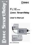
FL1E Series User’s Manual Supplement
New analog output module FL1D-K2BM2 is added in FL1E IDEC SmartRelay
series. And password protection function is available in the Text Display (version 4
or later). The following contents supplement FL1E series IDEC SmartRelay User’s
Manual (FL9Y-B1090).
When you use the FL1D-K2BM2, read this supplement and the latest FL1E series
IDEC SmartRelay User’s Manual and understand enough the feature and the
capability.
●You can download the latest user’s manual from the website.
http://www.idec.com/usa/index.html
Page 7
The analog output module (FL1D-K2BM2) structure
①Power supply
②Outputs
⑦RUN/STOP indicator
⑧Expansion interface
⑨Mechanical coding pins
Page 9
⑩Mechanical coding sockets
⑪Slide
⑫PE terminal, for connecting earth
⑬Version number
How to identify the IDEC SmartRelay
The IDEC SmartRelay identifier informs you of various properties.
Analog output module
FL1D-K①②③④
①Number of Outputs
②Resolution B: 10bit
③blank: 0 ... 10V M: 0 ... 10V, 0/4 ... 20mA
④Terminal type 2: non-removable terminal
1
B1090(0)-Supplement (September, 2009)
FL1E Series User’s Manual Supplement
Page 12
Symbol
L+M
Expansion modules
Name
Power supply
Inputs
Outputs
FL1D-K2BM2
24V DC
none
2 analog
0 ... 10V DC,
0/4 ... 20mA (4)
L+M
RUN/STOP
PE
OUTPUT 2x(0..10V or 0/4..20m
A)
V1+ M1 I1 V2+ M2 I2
(4): 0 ... 10V, 0/4 ... 20mA can be connected optionally.
Page 20
2.1.2 Setup with different voltage classes
Overview: Connecting an expansion module to the base module
In the following tables, “X” means that the connection is possible; “-” means that
the connection is not possible.
Base module
Expansion module
FL1D-K2BM2
FL1E-H12RCE
x
FL1E-H12SND
x
FL1E-H12RCA
x
FL1E-H12RCC
x
FL1E-B12RCE
x
FL1E-B12RCA
x
FL1E-B12RCC
x
Overview: Connecting an additional expansion module to an expansion module
Expansion
module
FL1DK2BM2
Additional expansion module
FL1BM08B2R2
FL1BM08B1S2
FL1BM08D2R2
FL1BM08C2R2
FL1DK2BM2
CM
x
x
x
-
x
x
When setting up expansion modules of different power voltages, take the following
restrictions into consideration.
Note
When you use a 24V DC power supply to supply power to 12/24V DC power type
base module and 24V DC power type expansion I/O modules, use a 24V DC power
supply which starts up within 10 seconds, otherwise the base module does not
recognize the expansion I/O modules. When the power supply voltage varies while
the base module and the expansion I/O modules are operating, they normally
operate within the permissible operating voltage range.
2
B1090(0)-Supplement (September, 2009)
FL1E Series User’s Manual Supplement
When using different power supplies, supply power to the base module and
expansion modules at the same time, or supply power to expansion modules before
the base module.When supplying power to expansion modules after the base module,
expansion modules may not be recognized by the base module. When using
different power supplies, the fast transient/burst immunity (IEC61000-4-4) will be 1
kV (power supply).
A 100 to 240V AC/DC module cannot be connected to the right side of a 12/24V
DC, 24V DC, or 24V AC/DC module. For analog input module and AS-Interface
communication module, a module of any voltage can be connected to the left side.
To the right side, however, a 100 to 240V AC/DC module cannot be connected.
Page 21
2.1.3 Compatibility
You can use FL1D-K2BM2 with equipment series FL1C or FL1D, but you cannot
use the module with equipment series FL1B or earlier.
Page 27
2.2.3 Mounting the Text Display
① Mounting brackets
② Mounting screws
③ Gasket
④ Cabinet door or control panel
(Thickness: 1.5 to 4 mm)
Note
The number of supplied mounting screws and brackets on the FL1E-RD1 text
display depends on the version. The version number of the FL1E-RD1 is found in
the lower-right corner on the back of the module. For identifying the version, see
page 5.
For versions 3 and earlier, 2 screws and brackets are provided.
For versions 4 and later, 4 screws and brackets are provided. Listed by UL type 4x /
12 for a tightening torque of 0.2 Nm.
3
B1090(0)-Supplement (September, 2009)
FL1E Series User’s Manual Supplement
Page 41
Connecting outputs
FL1D-K2B2
FL1D-K2BM2
L+
M
L+
M
L+ M
① Earth
② DIN rail
L +M
L+ M
L +M
2
2
RUN/STOP
RUN/STOP
1
PE
1
PE
OUTPUT 2x(0..10V)
OUTPUT 2x(0..10V or 0/4..20m
A)
V1+ M1
0~10V
R1
V2+ M2
V1+ M1 I1 V2+ M2 I2
0~10V
R1
V1, V2: 0 ... 10V
R1: >= 5kΩ
0
10V
R1
0/4~20mA
R2
V1, V2: 0 ... 10V
R1: >= 5kΩ
I1, I2: 0/4 ... 20mA
R2: <= 250Ω
Note
Caution for wiring the analog output terminals:
Check the analog output terminals, and wire each output terminal to the external
equipment, according to the type of analog outputs. Incorrect wiring may cause
damage to the equipment connected to the analog output terminals. The terminal
arrangement on the FL1D-K2BM2 is different from that of the FL1D-K2B2.
Check the analog output terminals on the FL1D-K2BM2, and replace the
FL1D-K2B2 with the FL1D-K2BM2.
4
B1090(0)-Supplement (September, 2009)
FL1E Series User’s Manual Supplement
Page 42
Output Internal Circuit
FL1D-K2BM2
Analog Output (0-10V)
+24V Internal Circuit
Internal
Circuit
+
(V1+, V2+)
-
10Ω
100nF
4.7kΩ
(M1, M2)
FL1D-K2BM2
Analog Output (0-20mA)
+14V Internal Circuit
Internal
Circuit
(I1, I2)
10nF
(M1, M2)
Page 72
3.6.5 Password
You can protect a circuit program from unauthorized access by assigning it a
password. You can only assign or deactivate a password from the IDEC SmartRelay
Base module or from WindLGC. You can only change a password from the IDEC
SmartRelay Base module. If you have assigned a password, and are using a Text
Display (version 4 or later) together with an IDEC SmartRelay Base module
(version 4 or later), you must enter this password if you want to change IDEC
SmartRelay from RUN mode to STOP mode from the Text Display. You can not
stop the execution of the circuit program in IDEC SmartRelay from the Text Display
without entering the password.
5
B1090(0)-Supplement (September, 2009)
FL1E Series User’s Manual Supplement
Note
This additional password protection function is only available in the Text Display
with version number 4 or later. This function is only available under the following
conditions:
• The version number of both the IDEC SmartRelay Base and the Text Display
installed is at least version 4
• IDEC SmartRelay is currently in RUN mode and you want to switch to STOP
mode
There is only one password that you can assign for IDEC SmartRelay. You can only
assign it from the IDEC SmartRelay base module or from WindLGC. To change
IDEC SmartRelay from RUN to STOP from the Text Display, you must enter the
password from the Text Display as described below in the section “Changing IDEC
SmartRelay from RUN to STOP mode from the Text Display”.
Page 74
Changing IDEC SmartRelay from RUN to STOP mode from the Text Display
A change from RUN mode to STOP mode from the Text Display requires password
entry if one is assigned. You must know the existing password if one is assigned. If
there is no password assigned on the IDEC SmartRelay Base module, the Text
Display will not prompt you for password entry. To change IDEC SmartRelay from
RUN mode to STOP mode from the Text Display when IDEC SmartRelay is
password-protected, follow these steps:
1. On the Text Display, press ESC to switch IDEC SmartRelay from RUN mode to
STOP mode. Text Display shows the following menu:
2. Press OK. The Text Display shows you the following display:
6
B1090(0)-Supplement (September, 2009)
FL1E Series User’s Manual Supplement
3. Press ▼ to move the cursor to “Yes”, and press OK. Enter the correct password
(in this case: “ZZ”). If you enter an incorrect password, the Text Display returns
to the display in Step 1.
4. Press OK to exit the password entry screen form. The Text Display opens the
main menu:
Note
Whenever the Text Display is initialized, the password needs to be inputted again.
The next time you start it and access this password-protected function (RUN to
STOP), you will be prompted for password entry on the Text Display.When IDEC
SmartRelay subsequently changes from STOP to RUN mode, you will again be
prompted for password entry to change IDEC SmartRelay to STOP mode from the
Text Display if more than one minute has elapsed since you pressed any key on the
Text Display.The Text Display can also change IDEC SmartRelay from STOP to
RUN mode, but no password is required in this case.
Page 88
Note
In case that you forget the password, you can delete the circuit program and the
password using WindLGC. See the onlinehelp for WindLGC for more details.
For a base module with versions 3 and earlier, you can delete the circuit program
and the password by inputting a wrong password on “Clear Prg” menu three times
in a row.
For a base module with versions 4 or later, you can delete the circuit program and
the password by inputting a wrong password on “Clear Prg” menu a hundred times
in a row.
7
B1090(0)-Supplement (September, 2009)
FL1E Series User’s Manual Supplement
Page 178
Analog output
Analog output can only process values between 0 and 1000. Connect an Analog
amplifier function block in front of the analog output function block to convert the
analog output of the special function block within a range between 0 and 1000. The
analog output range -5000 to 5000 of a special function block is converted to a
range between 0 and 1000 in the block diagram below.
When an analog signal out of the range between 0 to 1000 is inputted to an
analog output function block:
The analog output module operates as below for the analog signal out of the range
between 0 to 1000.
(1) When the type of analog outputs is set to 0-10V/0-20mA:
When internal values less than zero are inputted to the analog output function block,
the analog output module outputs 0V and 0mA. When internal values more than
1000 are inputted to the analog output function block, the analog output module
outputs 10V and 20mA.
The relationship between the internal value Ax inputted to the analog output
function block and the analog output value:
Analog output value
10V / 20mA
-1000
8
0
1000
Internal value Ax
B1090(0)-Supplement (September, 2009)
FL1E Series User’s Manual Supplement
(2) When the type of analog outputs is set to 4-20mA:
When internal values less than zero are inputted to the analog output function block,
the analog output module outputs current values less than 4mA. When internal
values more than 1000 are inputted to the analog output function block, the analog
output module outputs 20mA.
The relationship between the internal value Ax inputted to the analog output
function block and the analog output value:
Analog output value
20mA
4mA
-1000
-250
0
1000
lnternal value Ax
Note
Using an Analog trigger function block, you can determine that the internal values
less than zero or more than 1000 are inputted to the analog output function block.
When the type of analog outputs is set to 4-20mA, and internal values less than zero
are inputted to the analog output function block, it outputs current values less than
4mA. You may need to prevent the analog output module from outputting current
values less than 4mA. To do this, connect the Analog Multiplexer function block
(B007) in front of the analog output function block (AQ1) and connect the Analog
trigger function block (B006) in front of the Analog Multiplexer function block to
convert the internal values less than zero to internal values equal to or more than
zero.
9
B1090(0)-Supplement (September, 2009)
FL1E Series User’s Manual Supplement
In the block diagram below, the analog output module operates as the lower part of
the timing chart.
The relationship between the internal value Ax inputted to the analog output
function block and the analog output value:
Analog output value
20mA
4mA
-1000
0
1000
Internal value Ax
Set each parameter of the function blocks referring to the table below.
Parameters
Analog trigger
A : Gain = + 1.00
function block
B : Offset = 0
(B006 in the above table)
On : On threshold = 0
Off : Off threshold = 0
p : Number of decimals: arbitrary
Analog Multiplexer
V1 = 0
function block
V2 : arbitrary
(B007 in the above table)
V3 = Function block number with the actual
value Ax to be outputted from AQ1
V4 : arbitrary
p : Number of decimals: arbitrary
10
B1090(0)-Supplement (September, 2009)
FL1E Series User’s Manual Supplement
Page 239
Compatibility (Old memory cartridges in newer IDEC SmartRelay
modules)
... to earlier versions (FL1C and FL1D devices):
Data written to the memory cartridge in the FL1D can be read in all FL1E. But data
written to the memory cartridge in the FL1C cannot be read by the FL1E. When the
memory cartridge is read by the FL1E, the original data in the FL1E is deleted. Data
cannot be written from the FL1E to the memory cartridge.
Compatibility (New memory, battery, or combined memory/battery
cartridges in older IDEC SmartRelay modules)
The FL1E memory cartridge can be used in FL1C or FL1D devices but cannot be
used in FL1A..FL1B devices. Data written to the FL1E memory cartridge in the
FL1C cannot be read by the FL1E. When the memory cartridge is read by the FL1E,
the original data in the FL1E is deleted.
Note
For detail about the compatibility of SmartRelay and memory cartridges, refer to
FAQ available on IDEC website
(URL: http://www.idec.com/faq/en/controller/).
11
B1090(0)-Supplement (September, 2009)
FL1E Series User’s Manual Supplement
Page 309
A.11 Technical data: FL1D-K2BM2
FL1D-K2BM2
Power supply
Input voltage
Permissible range
Power consumption
Voltage failure buffering
Power loss at 24 V
Electrical isolation
Reverse polarity protection
Ground terminal
Analog outputs
Number
Voltage range
Voltage load
Current output
Current load
Resolution
Cycle time for analog output
Electrical isolation
Line length (shielded and
twisted)
Error limit
24V DC
20.4 ... 28.8V DC
35 ... 90mA
typ. 5ms
0.9 ... 2.2W
No
Yes
For connecting ground and shielding of
the analog output line.
2
0 ... 10V DC
>= 5kΩ
0/4 ... 20mA
<= 250Ω
10 bit, normalized to 0 ... 1000
depending on installation (typ. 50ms)
No
10m
Voltage output: +/- 2.5% at full scale
Current output: +/- 3% at full scale
Short circuit protection
Yes
Response at short-circuit
(1)
Overload protection
Yes
Response at overload
(1)
(1) Voltage output: If short-circuit protection or overcurrent protection is activated
for a voltage output, the error limit of the other voltage is not ensured.
12
B1090(0)-Supplement (September, 2009)