1
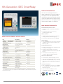
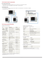
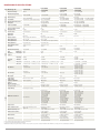
6th-Generation IDEC SmartRelay
PRODUCT DESCRIPTION
With an ever-changing market and
tough competition, you need an edge to
stay on top. This sixth-generation IDEC
SmartRelay meets your demands from all
small-scale applications by offering more
powerful hardware, a new display and full
communication options via Ethernet.
BASE MODULE HIGHLIGHTS
Embedded RJ45 Ethernet Port
• Remote program download, upload and
monitor
• Integrated web server for remote
monitoring and control
Micro SD Card
• Equipped with micro SD slot for program
storage, transfer and data logging
BASE MODULE GENERAL SPECIFICATIONS
Item
• No need for a special memory cartridge
Specifications
Standard
Horizontal Mounting
0 to 55°C (no freezing)
Vertical Mounting
0 to 55°C (no freezing)
Cold: IEC60068-2-1
Hot: IEC60068-2-2
Storage/Transportation Temp.
–40 to +70°C (no freezing)
—
Relative Humidity
10 to 95% (no condensation)
IEC60068-2-30
Atmospheric Pressure
795 to 1080hPa
—
Operating Condition
No corrosive gas
—
Degree of Protection
IP20
—
Vibration Resistance
5 to 8.4Hz, amplitude 3.5mm
8.4 to 150Hz, acceleration 9.8m/s²
IEC60068-2-6
Shock Resistance
147m/s²
IEC60068-2-27
Drop Test (packaged)
0.3m
IEC60068-2-32
Emissions
Limit class B Group 1
EN55011/A
EN55022/B
EN50081-1
Electrostatic Discharge Immunity
8kV air discharge
6kV contact discharge
IEC61000-4-2
Radiation Field Immunity
Field Strength:
1V/m and 10V/m
IEC61000-4-3
Fast Transient Burst
2kV (power line)
2kV (I/O signal line)
IEC61000-4-4
Surge Immunity1
1kV (power line) normal
2kV (power line) common
IEC61000-4-5
Communication Cable
2.5mm² (one wire)
1.5mm² (two wires)
—
Terminal Style
Finger-safe type 2
—
Operating
Temperature
(FL1F-H12RCC, FL1F-B12RCC only)
Data Logging
• Up to 20,000 lines in a file with a maximum
of 50 files can be stored in the Micro SD
Memory card
Integrated Web Server
• Easily monitor and control web pages with
no HTML knowledge
• Instant monitoring and control using
standard web browser like Chrome, IE and
Firefox
• View and control I/O status, timer,
counters, analog set point and more
There's an App for that!
• Download iOS and Android App for free
• Using the SmartRelay App, users can view
and control any I/O status, timer, counters,
and analog set point anywhere and at any
time
1:N Communication
• FL1F SmartRelays now have the capability
to communicate with each other over an
Ethernet network
1: For protection against surge noise on DC power supply types (FL1F-H12RCE/B12RCE, FL1F-H12SCD, FL1F-H12RCA/B12RCA), use surge absorbers,
noise cut transformers or noise filters. Use of a surge protection device (DEHN + SÖHNE GmbH + Co, BVT AD 24 Part No. 918 402) is recommended.
2: Tightening torque 0.5 to 0.6N·m
• Up to 16 FL1F SmartRelays can be
configured on the network
C
1
R
US
TEXT DISPLAY PANEL HIGHLIGHTS:
New and improved LCD display
• Improved display with 6 lines and 20 characters per line, more than twice as many characters as before
•
Selectable white, amber or red backlighting for optical emphasis on alarms and events
Two RJ45 Ethernet ports
• Use a standard Ethernet cable to the connect FL1F base module to the Text Display Panel. A special cable is not required.
•
Provide different ways to connect
TEXT DISPLAY SPECIFICATIONS
Text Display General Specifications
Item
Operating
Temperature
Specifications
Horizontal
Mounting
Vertical
Mounting
0 to 55°C (no freezing)
0 to 55°C (no freezing)
Text Display General Specifications Cont.
Standard
Cold: IEC60068-2-1
Hot: IEC60068-2-2
Storage/Transportation Temp.
–40 to +70°C (no freezing)
—
Relative Humidity
10 to 95% (no condensation)
IEC60068-2-30
Atmospheric Pressure
795 to 1080hPa
—
Operating Condition
No corrosive gas
—
Degree of Protection
IP20
—
Vibration Resistance
5 to 8.4Hz, amplitude
3.5mm
8.4 to 150Hz, acceleration
9.8m/s2
IEC60068-2-6
Shock Resistance
147m/s2
Drop Test (packaged)
0.3m
Emissions
Limit class B Group 1
Electrostatic Discharge
Immunity
8kV air discharge
6kV contact discharge
IEC61000-4-2
Radiation Field Immunity
Field Strength:
1V/m and 10V/m
IEC61000-4-3
Fast Transient Burst
2kV (power line)
2kV (I/O signal line)
IEC61000-4-4
1kV (power line) normal
2kV (power line) common
IEC61000-4-5
Communication Cable
2.5mm2 (one wire)
1.5mm2 (two wires)
—
Terminal Style
Finger-safe type2
—
Surge Immunity1
(FL1F-H12RCC, FL1F-B12RCC only)
Dimensions (W × H × D)
128.2 × 86 × 38.7 mm
Weight (approx.)
Installation
220g
Panel cut-out using mounting clips
Keyboard
Membrane keypad
Display
FSTN graphic display
(W × H: 160 × 96 dots)
LED backlight (White, Amber, Red)
Font type
English, Spanish, Russian, Chinese, Italian, Turkish,
German, Dutch, French, Japanese
Displayable string
1 screen 6 lines × 20 columns
Power Supply Specifications
Power Voltage
24V AC/DC
12V DC
IEC60068-2-27
Allowable Voltage Range
20.4 to 26.4V AC
10.2 to 28.8V DC
IEC60068-2-32
EN55011/A
EN55022/B
EN50081-1
Allowable Voltage Frequency
47 to 63Hz
Power Consumption
12V DC: 145mA (Typ.)
24V DC: 70mA (Typ.)
24V AC: 75mA (Typ.)
Data Transmission Rate
10/100M full/half duplex data transmission rate
LCD Display / Backlight Specifications
LCD Display Durability3
Backlight Durability
4
50,000 hours
20,000 hours
3 Display durability is calculated under ordinary operating and storage conditions: room temperature,
normal humidity below 65% RH, and not subjected to direct sunlight.
4 Backlight durability is the number of hours taken for the light to become 50% of the original brightness.
1 For protection against surge noise on DC power supply types (FL1F-H12RCE/B12RCE, FL1F-H12SCD, FL1FH12RCA/B12RCA), use surge absorbers, noise cut transformers, or noise filters. Use of a surge protection device
(DEHN + SÖHNE GmbH + Co, BVT AD 24 Part No. 918 402) is recommended.
2 Tightening torque 0.5 to 0.6N·m
2
PART NUMBERS
Base Module
Rated Power Voltage
Input Signal
24V DC
Output Signal
Display
Transistor
Yes
DC
I1, I2, I7 and I8 are used for digital/
analog inputs
12/24V DC
24V AC/DC
AC/DC
100 to 240V AC/DC
Yes
Relay
1
—
Yes
Relay
AC/DC
Clock
Yes
Yes
8/4 points
8/4 points
Yes
—
Weight (approx.)
8/4 points
Yes
—
Relay
I/O Points
Yes
8/4 points
Part No.
195g
FL1F-H12SCD
240g
FL1F-H12RCE
200g
FL1F-B12RCE
240g
FL1F-H12RCA
200g
FL1F-B12RCA
240g
FL1F-H12RCC
200g
FL1F-B12RCC
1 With NPN/PNP sensor input. For details, see Input Internal Circuits in the Specifications table.
Expansion I/O Module
Type
Rated Power Voltage
Input Signal
Output Signal
I/O Points
Weight (approx.)
Part No.
24V DC
DC
Transistor
4/4 points
95g
FL1F-M08B1S2
12/24VDC
DC
Relay
4/4 points
130g
FL1F-M08B2R2
24V AC/DC 2
AC/DC 2
Relay
4/4 points
130g
FL1F-M08D2R2
100 to 240V AC/DC
AC/DC
Relay
4/4 points
130g
FL1F-M08C2R2
Analog Input
12/24V DC
Analog
—
2/0 points
95g
FL1F-J2B2
Analog Output
24V DC
—
Analog
0/2 points
95g
FL1F-K2BM2
Input/Output
2 With NPN/PNP sensor input. For details, see Input Internal Circuits in the Specifications table.
I/O points within the maximum number of expandable I/O points can be used.
When using modules of the same power voltage, supply power to the base module and expansion I/O modules using one power supply.
When power is supplied to the modules from different power supplies, the fast transient burst is 1 kV (IEC61000-4-4).
Text Display
Rated Power Voltage
Weight (approx.)
Part Number
Remarks
24V AC/DC
12V DC
220g
FL1F-RD1
Supplied with mounting clip and gasket
Options
Description
Part Number
Package Quantity Remarks
Application Software: WindLGC
FL9Y-LP1CDW
1
DVD-ROM (incl. online help manual)
Mounting Clip for Base Module
FL1F-PSP1PN05
5
Supplied with a module 3
Mounting Clip and Waterproof Gasket for Text Display
FL1F-KW1
1
Supplied with text display4
IDEC SmartRelay User’s Manual (English)
FL9Y-B1789
1
Downloadable from: http://www.idec.com/download
3 Supplied with a base module and an expansion module.
4 Supplied with a text display, it includes a gasket, four mounting clips, and a power supply connector.
NEW FUNCTION BLOCKS
En
AQ
Lap
AX
R
Sn=8
Sn
1 2 3 4 5 6 7 8
Sn=8
Sn=8
Analog filter
Ax
Ax
En
Lap Sw
R
CurT
9 10 ...
Stopwatch
AQ
LapT
AQ
AQ
AQ
AX
Monday
Astronomical
clock
Tuesday
Ta
Ta
Ta
TR TS
TR TS
TR TS
AC
Sn
1
2 3
4
5
300
380
200
250
100 100
300
0
0
200
0 100
1
Ax
AQ
350
380
250
2
3
6
7 8
1
2 3
4
5
Average value
En
R
Ax
En
(If ERst=1)
S1
Mode
Q
Sn=8
St=10s
Ax
AQ
En
R
Q
300
Max/Min
Wednesday...
En
S1
Ax
Ax
AQ
3
Sn=8
St=10s
6
7 8
BASE MODULE SPECIFICATIONS
Base Module Type No.
Rated Power Voltage
Clock
Power Supply
Allowable Voltage Range
FL1F-H12RCE
FL1F-B12RCE
FL1F-H12RCA
FL1F-B12RCA
FL1F-H12RCC
FL1F-B12RCC
24V DC
12/24V DC
24V AC/DC
100 to 240V AC/DC
10.8 to 28.8V DC
20.4 to 26.4V AC
20.4 to 28.8V DC
85 to 265V AC
100 to 253V DC
20.4 to 28.8V DC
Rated Frequency
—
15 to 50 mA (24V DC)
1.2A (with max. load on digital output)
Current Draw
Allowable Momentary Power
Interruption
—
47 to 63Hz
47 to 63Hz
30 to 140 mA (12V DC)
15 to 90 mA (24V DC)
—
15 to 150mA (12V DC)
15 to 130mA (24V DC)
15 to 40mA (100V AC) 5 to 10mA (100V DC)
15 to 25mA (240V AC) 2 to 8mA (240V DC)
2ms Typ. (12V DC)
5ms Typ. (24V DC)
5ms Typ. (24V AC/DC)
10ms Typ. (100V AC/DC)
20ms Typ. (240V AC/DC)
3.6 W (24V AC)
3.2 W (24V DC)
4.6W (100V AC) 1.2W (100V DC)
6.0W (240V AC) 2.0W (240V DC)
Power Consumption
1.2 W (24V DC)
1.7W (12V DC)
2.2W (24V DC)
Reverse Polarity Protection
Yes
Yes
Backup Duration
20 days
20 days
20 days
20 days
Clock Accuracy
±2 sec/day (Typ.)
±2 sec/day (Typ.)
±2 sec/day (Typ.)
±2 sec/day (Typ.)
Input Signal
DC
DC
AC/DC
AC/DC
Input Points
8 (I1 to I8)
8 (I1 to I8)
8 (I1 to I8)
High-speed Input1
4 (I3, I4, I5, I6), 5kHz maximum
4 (I3, I4, I5, I6), 5kHz maximum
—
—
Analog Input Points
4 (I1, I2, I7, I8)
4 (I1, I2, I7, I8)
—
—
Analog Input Range
0 to 10V DC (max. rated input: 28.8V DC) 0 to 10V DC (max. rated input: 28.8V DC)
—
—
Analog Input Error
±1.5 (of full scale)
±1.5 (of full scale)
—
—
Analog Input Resolution
10 bits (0 to 1000)
10 bits (0 to 1000)
—
Cycle time
300ms
300ms
300ms
300ms
Allowable Voltage Range
0 to 28.8V DC
0 to 28.8V DC
0 to 26.4V AC
0 to 28.8V DC
0 to 265V AC
0 to 253V DC
Digital Input
5.8kΩ
5.8kΩ
4.8kΩ
Analog Input
72kΩ
72kΩ
Input
Impedance
Input
FL1F-H12SCD
Isolation
—
—
—
8 (I1 to I8)
—
610kΩ
—
—
—
—
—
OFF Voltage
< 5V DC
< 5V DC
< 5V AC/DC
< 40V AC
< 30V DC
ON Voltage
≥ 12V DC
≥ 8.5 V DC
≥ 12V AC/DC
≥ 79V AC
OFF Current
< 0.9mA (I3 to I6) < 0.07mA (I1, I2, I7, I8) < 0.88mA (I3 to I6) < 0.07mA (I1, I2, I7, I8) < 1.2mA
< 0.05mA (AC) < 0.06mA (DC)
ON Current
≥ 2.1mA (I3 to I6) ≥ 0.18mA (I1, I2, I7, I8)
≥ 1.5mA (I3 to I6) ≥ 0.12mA (I1, I2, I7, I8)
≥ 2.6mA
≥ 0.08mA (AC) ≥ 0.13mA (DC)
Turn ON Time
1.5ms (Typ.)
≤ 1.0ms (I3 to I6)
1.5ms (Typ.)
≤ 1.0ms (I3 to I6)
1.5ms (Typ.)
100V AC: 40ms (Typ.)
240V AC: 30ms (Typ.)
100V DC: 25ms (Typ.)
240V DC: 20ms (Typ.)
Turn OFF Time
1.5ms (Typ.)
≤ 1.0ms (I3 to I6)
1.5ms (Typ.)
≤ 1.0ms (I3 to I6)
15ms (Typ.)
100V AC: 45ms (Typ.)
240V AC: 70ms (Typ.)
100V DC: 60ms (Typ.)
240V DC: 75ms (Typ.)
Wire Length2
100m
100m
100m
100m
Output Signal
Output Points/
Contact Configuration
Transistor source output
Relay output
Relay output
Relay output
4 points (separate)
4NO contacts
4NO contacts
4NO contacts
—
Isolated
Isolated
Isolated
—
2500V AC, 1 minute
500V DC, 1 minute
2500V AC, 1 minute
500V DC, 1 minute
2500V AC, 1 minute
500V DC, 1 minute
Operating
Range
Isolation
Dielectric Strength
(between power/input terminals
and output terminals)
Output Voltage
External power voltage
—
≥ 79V DC
—
—
Resistive load
10A at 12/24V AC/DC
10A at 100/120V AC
10A at 230/240V AC
0.2A at 120V DC
0.1A at 240V DC
Inductive load
2A at 12/24V AC/DC
3A at 100/120V AC
3A at 230/240V AC
0.2A at 120V DC
0.1A at 240V DC
Resistive load
10A at 12/24V AC/DC
10A at 100/120V AC
10A at 230/240V AC
0.2A at 120V DC
0.1A at 240V DC
Inductive load
2A at 12/24V AC/DC
3A at 100/120V AC
3A at 230/240V AC
0.2A at 120V DC
0.1A at 240V DC
Resistive load
10A at 12/24V AC/DC
10A at 100/120V AC
10A at 230/240V AC
0.2A at 120V DC
0.1A at 240V DC
Inductive load
2A at 12/24V AC/DC
3A at 100/120V AC
3A at 230/240V AC
0.2A at 120V DC
0.1A at 240V DC
30A maximum
30A maximum
30A maximum
External fuse required:
16A maximum
External fuse required:
16A maximum
External fuse required:
16A maximum
—
10mA, 12V DC (reference value)
10mA, 12V DC (reference value) 10mA, 12V DC (reference value)
Initial Contact Resistance
—
100mΩ maximum
(at 1A, 24V DC)
100mΩ maximum
(at 1A, 24V DC)
100mΩ maximum
(at 1A, 24V DC)
Mechanical Life
—
10 million operations
(no load, 10Hz)
10 million operations
(no load, 10Hz)
10 million operations
(no load, 10Hz)
Electrical Life
—
100,000 operations
(rated resistive load)
1800 operations/hour
100,000 operations
(rated resistive load)
1800 operations/hour
100,000 operations
(rated resistive load)
1800 operations/hour
Output
Maximum Load Current
Surge Current
Short-circuit Protection
Minimum Switching Load
0.3A maximum
—
Built-in current limiting resistor:
Approx. 1A
1 When selecting frequency trigger function and up/down counter function.
2 10m when connected to analog input (twisted pair cable)
Initialization Time: After power-up, the FL1F takes a maximum of 9 seconds (when using a micro SD card) for initialization. When initialization is complete, the FL1F is automatically set to RUN mode.
4
EXPANSION I/O MODULE SPECIFICATIONS
Expansion I/O Module Type No.
FL1F-M08B1S2
FL1F-M08B2R2
FL1F-M08D2R2
Rated Power Voltage
24V DC
12/24V DC
Allowable Voltage Range
20.4 to 28.8V DC
24V AC/DC
20.4 to 26.4V AC
20.4 to 28.8V DC
50/60Hz (47 to 63Hz)
Power Supply
Rated Frequency
Current Draw
—
15 to 40mA
10 to 80mA (12V DC)
10 to 40mA (24V DC)
Allowable Momentary Power
Interruption
—
Power Consumption
Input
1.0W
Reverse Polarity
Protection
Input Signal
Input Points
Isolation
DC input
Allowable Voltage Range
2 ms (typ.) (12V DC)
5 ms (typ.) (24V DC)
1.0W (12V DC)
1.0W (24V DC)
Yes
Yes
DC input
—
20.4 to 28.8V DC
10.8 to 28.8V DC
OFF Voltage
ON Voltage
< 5V DC
≥ 12V DC
< 5V DC
≥ 8.5V DC
AC/DC input
4
—
20.4 to 26.4V AC
20.4 to 28.8V DC
< 5V AC/DC
≥ 12V AC/DC
OFF Current
< 0.88mA
< 0.88mA
< 1.1mA
ON Current
≥ 2.1mA
≥ 1.5mA
≥ 2.63mA
Turn ON Time
1.5ms (Typ.)
1.5ms (typ.)
1.5ms (typ.)
Turn OFF Time
1.5ms (Typ.)
1.5ms (typ.)
15ms (typ.)
Operating
Range
4
—
4
—
FL1F-J2B2
FL1F-K2BM2
12/24V DC
24V DC
10.8 to 28.8V DC
20.4 to 28.8V DC
—
—
15 to 30mA
15 to 82mA
10ms (typ.) (12/24V DC)
0.4W (12V DC)
0.8W (24V DC)
10ms (typ.)
2.0W
—
Yes
Yes
4
—
Analog input
—
—
—
—
—
—
—
—
—
—
—
—
—
—
—
—
—
—
—
—
AC/DC input
  85 to 265V AC
100 to 253V DC
< 40V AC < 30V DC
≥ 79V AC ≥ 79V DC
< 0.05mA (AC)
< 0.06mA (DC)
≥ 0.08mA (AC)
≥ 0.13mA (DC)
100V AC: 40 ms (typ.)
240V AC: 30 ms (typ.)
100V DC: 25 ms (typ.)
240V DC: 20 ms (typ.)
100V AC: 45 ms (typ.)
240V AC: 70 ms (typ.)
100V DC: 60 ms (typ.)
240V DC: 75 ms (typ.)
—
Analog Input Points
—
—
—
Analog Input Range
—
—
—
—
Digital Resolution
Input Error
—
—
—
—
—
—
—
—
Input Impedance
—
—
—
—
Sampling Cycle
—
—
—
—
Wire Length
100m
100m
100m
100m
Output Signal
Output Points/
Contact Configuration
Isolation
Dielectric Strength
Transistor source output
Relay output
Relay output
Relay output
2
0 to 10V
(max. rated input: 28.8V)
0 to 20mA
(max. rated input: 40mA)
10 bits (0 to 1000)
±1.5% (of full scale)
76kΩ (0 to 10V)
250Ω (0 to 20mA)
50ms
10m (twisted-pair
shielded cable)
—
4 points (separate)
4NO contacts
4NO contacts
4NO contacts
—
—
—
Isolated
Isolated
Isolated
—
—
—
2500V AC, 1 minute
500V DC, 1 minute
2500V AC, 1 minute
500V DC, 1 minute
2500V AC, 1 minute
500V DC, 1 minute
—
—
Output Voltage
External power voltage
(20.4 to 28.8V DC)
(between power/input terminals
and output terminals)
Output
10.8 to 28.8V DC
—
FL1F-M08C2R2
100 to 240V AC/DC
85 to 265V AC
100 to 253V DC
50/60Hz (47 to 63Hz)
10 to 30mA (100V AC)
20 to 100mA (24V AC) 10 to 20mA (240V AC)
8 to 50mA (24V DC)
  5 to 15mA (100V DC)
  5 to 10mA (240V DC)
(typ) (100V AC/DC)
5 ms (typ.) (24V AC/DC) 10ms
20ms (typ.) (240V AC/DC)
2.4W (24V AC)
3.5W (100V AC) 1.8W (100V DC)
1.2W (24V DC)
4.8W (240V AC) 2.4W (240V DC)
—
—
—
—
—
—
—
—
—
—
—
—
Resistive load
5A at 12/24V AC/DC
5A at 100/120V AC
5A at 230/240V AC
0.2A at 120V DC
0.1A at 240V DC
Inductive load
2A at 12/24V AC/DC
3A at 100/120V AC
3A at 230/240V AC
0.2A at 120V DC
0.1A at 240V DC
Resistive load
5A at 12/24V AC/DC
5A at 100/120V AC
5A at 230/240V AC
0.2A at 120V DC
0.1A at 240V DC
Inductive load
2A at 12/24V AC/DC
3A at 100/120V AC
3A at 230/240V AC
0.2A at 120V DC
0.1A at 240V DC
—
—
External fuse required:
16A maximum
External fuse required:
16A maximum
—
Yes
10mA, 12V DC
(reference value)
100mΩ maximum
(at 1A, 24V DC)
10 million operations
(no load, 10Hz)
100,000 operations
(rated resistive load)
1800 operations/hour
—
10mA, 12V DC (reference value)
—
—
100 mΩ maximum
(at 1A, 24V DC)
10 million operations
(no load, 10Hz)
100,000 operations
(rated resistive load)
1800 operations/hour
—
—
—
—
—
—
—
—
Analog Output Points
—
Resistive load
5A at 12/24V AC/DC
5A at 100/120V AC
5A at 230/240V AC
0.2A at 120V DC
0.1A at 240V DC
Inductive load
2A at 12/24V AC/DC
3A at 100/120V AC
3A at 230/240V AC
0.2A at 120V DC
0.1A at 240V DC
External fuse
required:
16A maximum
10mA, 12V DC
(reference value)
100mΩ maximum
(at 1A, 24V DC)
10 million operations
(no load, 10Hz)
100,000 operations
(rated resistive load)
1800 operations/hour
—
Analog Output Range
—
—
—
—
—
Digital Resolution
—
—
—
—
—
Output Error (of full scale)
—
—
—
—
—
Output Impedance
—
—
—
—
—
Analog Value
Conversion Interval
2
Voltage: 0-10V DC
Current: 0-20, 4-20 mA
10 bits (0 to 1000)
Voltage output: ±2.5%
Current output: ±3%
Voltage: 5kΩ min
Current: 250Ω max
—
—
—
—
—
50ms (typ.)
Wire Length
—
—
—
—
—
10m (twisted-pair
shielded cable)
Maximum Load Current
0.3A maximum
Short-circuit Protection
Built-in current limiting
resistor: Approx. 1A
Minimum Switching Load
—
Initial Contact Resistance
—
Mechanical Life
—
Electrical Life
—
5
(All dimensions in mm)
Base Module (with Display)
Base Module (without Display)
Base Module (with Display)
Mounting Hole Layout (Using Mounting Slides)
98 +/- 0.3
90
53.5
+0.2
-0.0
➁
➀
55
71.5
Expansion I/O Module
35.5
+0.2
-0.0
35.5
➁
➁
n x 35.5
60
+0.2
-0.0 35.5
➁
+0.2
-0.0 35.5
➁
+0.2
-0.0 35.5
➁
+0.2
-0.0
➁
+0.2
-0.0
Text Display
90
86
Base Module (without Display)
77.6
DIMENSIONS
31.9
34.7
38.7
128.2
71.5
53
58
Expansion I/O Module
(Panel Cutout)
Mounting clip
90
119.0+0.5mm
53
58
78.5+0.5mm
35.5
Mounting screws
(tightening torque:
0.15 to 0.2N·m)
Mounting clip
Gasket
Panel (thickness: 1.5 to 4mm)
Note: Drawings are not to scale
IDEC Corporation • 1175 Elko Drive • Sunnyvale, CA 94089 • 800-262-IDEC (4332) • Fax: 408-745-5258 • www.IDEC.com/usa
©2015 IDEC Corporation. All Rights Reserved. FL9Y-DS100-0a 10/15 PDF Only


![取扱説明書[NR-B6W] (2.65 MB/PDF)](http://vs1.manualzilla.com/store/data/006674157_2-0a7a4fa96814ebd585658af40b25d6b7-150x150.png)