1
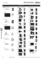
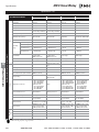
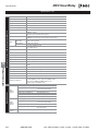
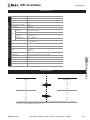
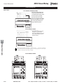
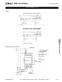
H
www.idec.com/smartrelay
Additional Web Resources
• New and updated product information
• Downloadable software demos & upgrades
• Part configuration tool & cross reference
• Online stock check & ordering
• IDEC field sales & distributor search
• Online literature request
• Downloadable manuals & CAD drawings
• Manufacturer’s suggested retail price list
• Product training schedule & locations
• Advertising & trade show schedules
• Press releases & FAQs
www.idec.com/smartrelay
for more information on this product family visit
IDEC SmartRelay
Section
Features..............................................H-2
Selection Guide..................................H-3
Function Blocks.................................H-4
Specifications ....................................H-5
Connection Diagrams .....................H-10
Dimensions.......................................H-12
General Information ......................H-13
Programming
• WindLGC . . . . . . . . . . . . . . . . . . .H-14
IDEC SmartRelay
Features
IDEC SmartRelay
IDEC SmartRelay –the smart and expandable solution
Get smart with the fully programmable IDEC
SmartRelay, a compact, expandable CPU that can
replace multiple timers, relays and counters. Each
CPU houses a real-time clock and calendar, and
supports optional expansion I/O modules to
enhance your control and monitoring applications.
Program and edit using either the "smart" onboard selection buttons and display interface, or
our even "smarter" software, WindLGC. The IDEC
SmartRelay is the ideal solution for managing
automatic lighting, access control, watering systems, pump control, or ventilation systems in factory or home automation.
HIghlights of the FL1C series
• 32-bit processor
• 130 connectable blocks
• 4 new function blocks
• 4 x12 backlight display
• Timer and counter frequency up to 2KHz
• Online monitor
• Ladder programming
• Invert of inputs saves NOT function blocks
LCD Display Panel
Display up to 48 characters as a
text message. Monitor any of the 8
basic or 26 special function blocks,
or confirm the status of the program
for troubleshooting.
Digital/Analog Inputs
(6 Digital plus 2 Digital or Analog)
Multiple inputs provide direct communication
with pushbuttons, sensors, switches, etc.
(2kHz max. on I5 and I6). (Common use I/O for
digital and analog: I7 and I8 on FL1C-H12RCE,
FL1C-B12RCE, FL1C-H12SND.) Expandable up
to 24 digital inputs.
H
IDEC SmartRelay
Operational Control Buttons
Easy programming interface uses
only six buttons. No tools necessary.
Cursor keys can also be configured as
inputs.
Multifunction Interface
A multifunction interface makes it easy to
insert and remove the memory cartridge
that controls the circuit program. It also
supports the PC interface cable for uploading and downloading data from WindLGC.
Other Key Features
Digital Outputs
Use the outputs to control lights,
small-sized motors and solenoid
valves up to 10A. Expandable up
to 16 digital outputs.
• Password protection
• Daylight savings time
• UL/c-UL listed, IEC61131/VDE0631,
EMC Compliant, C-tick listed
• FM approved for Class 1, Div 2 Class
1, Zone 2 hazardous locations.
Other Characteristics
Memory Cartridge
Text Display
Operational Buttons
It can display messages with
background lighting up to 48
characters long from a
selection of 97 character
types.
Use the selection buttons for
easy confirmation or modification of the circuit being
displayed. The cursor keys
can be configured as inputs.
H-2
www.idec.com
FL1C-PM3 is a memory cartridge
with know-how protection. Not
only is it possible to save your
program, but also to protect it
from unintended modification,
copying or deletion.
Not required for operation.
Expansion Modules
Optional expansion I/O modules allow you to add digital
input, output and LONWORKS®/
AS-Interface communication
modules as well as analog
inputs to your system. Just
snap-on and go – no special
software or cables required.
USA: (800) 262-IDEC or (408) 747-0550, Canada: (888) 317-IDEC
IDEC SmartRelay
Selection Guide
Part Numbers
Base Module Part Number
Part Number
Rated Voltage
FL1C-H12RCE
FL1C-B12RCE
FL1C-H12SND
FL1C-H12RCA
FL1C-B12RCA
FL1C-H12RCC
FL1C-B12RCC
12/24V DC
Input Signal
DC
I7and I8 are used
for digital/analog
24V DC
Input Type
24V AC/DC
Yes
—
Transistor Source Output
Yes
—
Relay Output
Yes
PNP
Expansion Module Part Number
Part No.
Module
FL1B-M08B2R2
Combination I/O Module
FL1B-M08D2R2
With Clock
Input/Output
Yes
—
Yes
PNP/NPN
100-240V AC/DC
FL1B-M08C2R2
With Display
Relay Output
PNP
AC/DC
FL1B-M08B1S2
Output Signal
8/4
Yes
—
Power Voltage
Input
Output
Total I/O
12/24V DC
DC input
Relay output
8 (4 in/4 out)
24V DC
DC input
Transistor output
8 (4 in/4 out)
100-240V AC/DC
AC/DC input
Relay output
8 (4 in/4 out)
24V AC/DC
AC/DC input
Relay output
8 (4 in/4 out)
FL1B-J2B2
Analog Input Module
12/24V DC
Analog input
–
2 (2 in/0 out)
FL1B-CL1C12
LONWORKS® Communication Module*
24V AC/DC
–
–
–
FL1B-CAS2
AS-Interface Communication Module*
30V DC
_
_
_
* For more information see Section M, Communications & Networking.
H
IDEC SmartRelay
Starter Kit Part Number
Description
Part Number
SMARTSTART-BAC-C
FL1C-B12RCC, WindLGC software, and programming cable
SMARTSTART-BDC-C
FL1C-B12RCE, WindLGC software, programming cable, and simulator switch
SMARTSTART-HAC-C
FL1C-H12RCC, WindLGC software, and programming cable
SMARTSTART-HDC-C
FL1C-H12RCE, WindLGC software, programming cable, and simulator switch
Accessories
Part Number
Description
Note
FL1C-PM3
Memory Cartridge
Memory cartridge with know-how protection
FL9Y-LP1CDW
Programming Software: WindLGC Ver. 4
CD w/Online Manual
FL1A-PC1
PC Interface Cable
Connection of SmartRelay to PC
BAA1000
BNDN1000
35MM DIN Rail
Aluminum, 1m/3.28ft
BNL6
Mounting Clips
MT-101
Memory Cartridge Removal Tool
FL1B-PSP1
Direct Mounting Slides
FL1B-Y1371-SW8
8pt simulator switch
FL9Y-B827
FL1C user’s manual
FC4A-USB
USB/RS232 converter
www.idec.com
used with 12, 24V DC base module only
USA: (800) 262-IDEC or (408) 747-0550, Canada: (888) 317-IDEC
H-3
IDEC SmartRelay
Function Blocks
Function Blocks
General Function Blocks
• AND
Special Function Blocks
1
2
3
4
Series connection of
normally open contacts
• On-delay
&
Q
• Operating hours counter
Trg
Par
Trg
Q
Q
T
OT
Q
• Off-delay
AND
I1
I2
I3
I4
Q
Cycle
1
2
3
4
5
6
7
8
9
10
1
2 &
3
4
Trg
R
Par
T
Q
Q
EN
Inv
Q
TH
TH
Q
Q
TL
T Starts
TH
Trg
R
Q
Parallel connection of
normally closed contacts
&
T
Q
IDEC SmartRelay
Cycle
1
2
3
4
5
6
7
8
9
10
Edge detection with
edge evaluation (pos. edge)
1
2 &
3
4
S
R
Q
Fre
G-T
Q
Parallel connection of
normally open contacts
1s
1000
SW
SW
T
Series connection of
normally closed contacts
A/2 0
A/1-A/2 0
Q
Q
T
1s
• Dual-function switch
Trg
TL
TL
Q
Sa Su
ON 12:00
OFF 20:00
Su
ON 8:00
OFF 22:00
TIL
T1
T
No2
12
Su
20 12 20
8
12 20 8
22
20
MM.DDt
No1
No2
No3
Fed. Mar. Apr.
No 02.25
No 04.15
Q
Double changeover contact
Q
No
25
25
MM
DD Q
R
Cnt
Dir 3
Par 21
0
R
Cnt
Dir
Par
En
P
Par
Q
EN
En
Par
Q
Q
Q
• Analog amplifier
Ax
Par
Q
• Analog differential trigger
1
Connection of closed contact
o
n
OFF=On+?
1
Q
AX
Q
OFF=On+?
• Shift register
Ax
Par
Q
AX
Q
En
Aen+?
Aen
Aen-?
AX
Q
www.idec.com
En
Ax
Par
In
Trg
Q
Dir
S1
S2
S3
S4
S5
S6
S7
S8
• Analog value monitoring
H-4
Q
• Softkey
Q
• NOT
Trg
R
Par
• Message texts
Switch
• Up/down counter
Q
Q
15s
Q
• Twelve-month time switch
1
2
Trg
Par
• Stairwell light switch
T Starts
T
Q
=1
Q
tor ?=200
Par
No1
• XOR
Ax
Ay
Par
Q -200
Trg
R
Trg
Sa
Q
Q
Trg
Q
1
Ax
Par
A/1 0
1000
• Seven-day time switch
1
2
3
4
Q
1000
Q
1000
200
Trg
Par
TStarts
• NOR
Fre
Par
• Analog comparator
S
R
Par RS
• Edge-triggered interval
time-delay relay
Q
fa=3Hz
1s
Q
• Interval time-delay relay/
Pulse output
1
fa=5Hz
A/1 or 0
A/2
Trg
Trg
Q
1
2
3
4
Q
TL
• Analog trigger
RS
Par
S
R
Q
Q
• OR
En
Par
• Latching relay
Trg
I1
I2
I3
I4
Q
H
T
Q
• Current impulse relay
NAND
Q
• Frequency trigger
Trg
R
Par
S
R
Q
• NAND (Edge)
En
Inv
Par
Trg
• Retentive on-delay
1
2
3
4
Q
• Random generator
Trg
Par
Q
• NAND
TL
• On-/Off-delay
Trg
Edge detection with
edge evaluation (pos. edge)
h
• Asynchronous pulse generator
Trg
R
Q
• AND (Edge)
R
En
Ral
Par
R
En
Ral
Mi
Mn
Q
0
0
0
0
1
1
0
0
Shift Up
1
0
0
0
0
1
1
0
0
1
0
0
0
0
1
1
1
0
1
0
0
0
0
1
1
1
0
1
0
0
0
0
0
1
1
0
1
0
0
0
1
1
0
1
0
0
0
1
In
Trg
Dir
Par
Q
S4=Q (Example)
Shift Down
USA: (800) 262-IDEC or (408) 747-0550, Canada: (888) 317-IDEC
IDEC SmartRelay
Specifications
Specifications
Item
Specifications
Compliant Standards
Dimensions (W x H x D)
72 x 90 x 55 mm
—
Weight
Approx. 190g
—
Horizontal
0 to +55°C
Vertical
0 to +55°C
Cold: IEC60068-2-1
Hot: IEC60068-2-2
Storage temperature
-40 to +70°C
—
Relative humidity
10 to 85%
IEC60068-2-30
Pressure
795 to 1080 hPa
—
Corrosion immunity
Free from corrosive gases
—
Degree of protection
IP20
Vibration resistance
5 to 9Hz (amplitude: 3.2mm)
9 to 150Hz (acceleration: 10m/s2)
IEC60068-2-6
Shock resistance
150 m/s2
IEC60068-2-27
Dropping
50 mm (Drop height)
IEC60068-2-31
Free fall (packaged)
1m
IEC60068-2-32
Emission
EMC
General Specifications
Operating
temperature
EN55011
—
EN50081-2, EN50082-2
Electrostatic discharge
8kV Air Discharge
6kV Contact Discharge
IEC61000-4-2
Electromagnetic fields
10V/m
IEC61000-4-3
Burst pulses
2KV (Supply and Signal Lines)
IEC61000-4-4
Energy carriers single pulse (surge)
0.5kV(Power Lines): Symmetrical
1kV (Power Lines): Asymmetrical
IEC61000-4-5
2 x 1.5 mm2,
1 x 0.5 to 2.5 mm2
—
Communication cable
H
IDEC SmartRelay
Class B Group 1
Emitted interference
Base Module Specifications
Power Supply
Clock
Base Module Operating Specifications
Base Module Part Number
FL1C-H12RCE
FL1C-H12SND
–
FL1C-H12RCC
FL1C-B12RCA
FL1C-B12RCC
Rated voltage
12/24V DC
24V DC
24V AC/DC
100-240V AC/DC
Allowable Voltage Range
10.8-28.8V DC
20.4-28.8V DC
20.4V-26.4V AC
20.4V-28.8V DC
85-265 AC
100-253 V DC
Rated Frequency
—
—
47-63Hz
50/60Hz (47-63Hz)
Input Current
30-140 mA (12V DC)
20-75 mA (24V DC)
30-55 mA (24V DC)
40-110 mA (24V AC)
20-75 mA (24V DC)
10-40 mA (100V AC)
10-25 mA (240V AC)
5-25mA (100V DC)
5-15mA (240V DC)
Allowable Momentary
Power Interruption
2 ms (12V DC)
5 ms (24V DC)
—
5 ms
10 ms (100V AC)
20 ms (240V AC)
Power Consumption
0.3-1.7W (12V DC)
0.4-1.8W (24V DC)
0.7-1.3W (24V DC)
0.9-2.7W (24V AC)
0.4 to1.8W (24V DC)
1.1-4.6W (100V AC)
2.4-6.0W (240V AC)
0.5-2.9W (100V DC)
1.2-3.6W (240V DC)
Reverse Polarity Protection
Yes
Yes
—
—
Backup Duration
80h at 25°C
—
80h at 25°C
80h at 25°C
Clock Accuracy
±2s / day maximum
—
±2s / day maximum
±2s / day maximum
www.idec.com
FL1C-B12RCE
FL1C-H12RCA
USA: (800) 262-IDEC or (408) 747-0550, Canada: (888) 317-IDEC
H-5
IDEC SmartRelay
Specifications
Specifications con’t
Base Module Part Number
Input Signal
Input
Switching
Rate
Output
Base Module Operating Specifications (con’t)
FL1C-B12RCE
–
DC
FL1C-H12RCA
FL1C-H12RCC
FL1C-B12RCA
FL1C-B12RCC
AC/DC
AC/DC
Input Points
8 (I1-I8)
8 (I1-I8)
8 (I1 - I8)
8 (I1-I8)
Analog Input Points
2 (I7, I8)*
2 (I7, I8)*
—
—
Fast Inputs
2 (I5, I6) Max 2KHz**
2 (I5, I6) Max 2 KHz**
—
—
Analog Input Voltage Range
0 to10V DC (maximum
rated voltage: 28.8V DC)
0 to 10V DC (maximum
rated voltage: 28.8V DC)
—
—
Rated Input Voltage
12/24V DC
24V DC
24V AC/DC
100-240V AC/DC
20.4-28.8V DC
0-26.4V AC
0-28.8V DC
85-253V AC, 100-253 VDC
Isolation
10.8-28.8V DC
Not Isolated
Not Isolated
Not Isolated
Not Isolated
Turn OFF Voltage
< 5V DC
< 5V DC
< 5V AC/DC
< 40V AC, < 30 VDC
Turn ON Voltage
> 8V DC
> 8V DC
> 12V AC/DC
> 79V AC, > 79VDC
Turn OFF Current
< 1.0 mA (I1-I6)
< 0.05 mA (I7-I8)
< 1.0 mA (I1-I6)
< 0.05 mA (I7-I8)
< 1.0 mA
< 0.03 mA
Turn ON Current
> 1.5 mA (I1-I6)
> 0.1 mA (I7-I8)
> 1.5 mA (I1-I6)
> 0.1 mA (I7-I8)
> 2.5 mA
> 0.08 mA
Turn ON Time
1.5ms (Typ.) (I1-14)
<1.0ms (I5, I6)
300ms Typ. (I7, I8)
1.5ms (Typ.) (I1-14)
<1.0ms (I5, I6)
300ms Typ. (I7, I8)
1.5 ms (Typ.)
50 ms (Typ.)
Turn OFF Time
1.5ms (Typ.)
1.5 ms (Typ.)
15 ms (Typ.)
50 ms (Typ.)
Wire Length
100m
100m
100m
100m
Output Signal
Relay Output
Transistor Source Output
Relay Output
Relay Output
Output Type
4NO contacts
4 points
4NO contacts
4NO contacts
Isolation
Isolated
Not Isolated
Isolated
Isolated
Dielectric Strength (between power/
input terminal and output terminals)
2,500V AC/1 minute
500V DC/1 minute
—
2,500V AC/1 minute
500V DC/1 minute
2,500V AC/1 minute
500V DC/1 minute
Output Voltage
—
Ext. power supply
20.4-28.8V DC
—
—
Maximum Load Current
Resistive Load
10A at 12/24V AC/DC
10A at 100/120V AC
10A at 230/240V AC
Inductive Load
2A at 12/24V AC/DC
3A at 100/120V AC
3A at 230/240V
0.3A
Resistive Load
10A at 12/24V AC/DC
10A at 100/120V AC/DC
10A at 230/240V AC/DC
Inductive Load
2A at 12/24V AC/DC
3A at 100/120V AC/DC
3A at 230/240V AC/DC
Resistive Load
10A at 12/24V AC/DC
10A at 100/120V AC
10A at 230/240V AC
Inductive Load
2A at 12/24V AC/DC
3A at 100/120V AC
3A at 230/240V AC
Short Circuit Protection
External fuse
16A maximum
Internal current
limiting circuit: 1A
External fuse
16A maximum
External fuse
16A maximum
Minimum Switching Load
10 mA, 12V DC
—
10 mA, 12V DC
10 mA, 12V DC
Initial Contact Resistance
100 mΩ maximum
(at 1A, 24V DC)
—
100 mΩ maximum
(at 1A, 24V DC)
100 mΩ maximum
(at 1A, 24V DC)
Mechanical Life
10,000,000 operations
minimum (no load, 10Hz)
—
10,000,000 operations
min (no load, 10Hz)
10,000,000 operations
minimum (no load, 10Hz)
Electrical Life
100,000 operations minimum (rated load 10A,
1,800 operations/hour)
—
100,000 operations min
(rated load 10A, 1,800
operations/hour)
100,000 operations minimum (rated load 10A,
1,800 operations/hour)
Mechanical Load
10 Hz
—
10 Hz
10 Hz
Operating
Range
IDEC SmartRelay
FL1C-H12SND
DC
Allowable Voltage Range
H
FL1C-H12RCE
Electrical Load
—
10 Hz
—
—
Resistive Load/Lamp Load
2 Hz
10 Hz
2 Hz
2 Hz
Inductive Load
0.5 Hz
0.5 Hz
0.5 Hz
0.5 Hz
* Input terminals 17 and 18 are used for digital and analog inputs.
** When selecting frequency trigger function.
H-6
www.idec.com
USA: (800) 262-IDEC or (408) 747-0550, Canada: (888) 317-IDEC
IDEC SmartRelay
Specifications
Specifications con’t
Power Supply
Expansion I/O Part Number
12/24V DC
24V DC
Allowable Voltage Range
10.8-28.8V DC
20.4-28.8V DC
Rated Frequency
—
—
24V AC/DC
20.4V-26.4V AC
20.4V-28.8V DC
47-63Hz
Input Current
30-140 mA (12V DC)
22-75 mA (24V DC)
30-45 mA (24V DC)
40-110 mA (24V AC)
20-75 mA (24V DC)
Allowable Momentary
Power Interruption
2 ms (12V DC)
5 ms (24V DC)
—
5 ms
Power Consumption
0.3-1.7W (12V DC)
0.4-1.8W (24V DC)
0.8-1.1W (24V DC)
0.9-2.7W (24V AC)
0.4 to 1.8W (24V DC)
Reverse Polarity Protection
Input Signal
Input Points
Analog Input Points
Yes
DC
4
—
Yes
DC
4
—
Input Impedance
—
—
—
Analog Input Range
—
—
—
Digital Resolution
Rated Input Voltage
—
12/24V DC
10.8-15.6V DC
20.4-28.8V DC
Not Isolated
—
24V DC
Input
Isolation
20.4-28.8V DC
Not Isolated
—
AC/DC
4
—
24V AC/DC
0-26.4V AC
0-28.8V DC
Not Isolated
100-240V AC/DC
85-265V AC
100-253V DC
50/60Hz (47-63Hz)
10-30 mA (100V AC)
10-20 mA (240V AC)
5-15mA (100V DC)
5-10mA (240V DC)
10 ms (100V AC)
20 ms (240V AC)
1.1-3.5W (100V AC)
2.4-4.8W (240V AC)
0.5-1.8W (100V DC)
1.2-2.4W (240V DC)
—
AC/DC
4
—
—
100-240V AC/DC
85-253V AC
100-253V DC
Isolated
< 40V AC
< 30V DC
> 79V AC
> 79V DC
< 0.3 mA
> 0.08 mA
50 ms (Typ.)
50 ms (Typ.)
Analog Input Module
FL1B-J2B2
12/24V DC
10.8-15.6V DC
20.4-28.8V DC
—
25-50mA
5 ms
0.3-0.6W (12V DC)
0.6-1.2W (24V DC)
Yes
Analog
—
2
76 kΩ (0-10V DC)
155-250 Ω (0-20mA DC)
0-10V DC (28.8V max)
0-20mA (40mA max)
10 bits (0-1000)
—
—
Not Isolated
Turn OFF Voltage < 5V DC
< 5V DC
< 5V AC/DC
Turn ON Voltage
> 8V DC
> 8V DC
> 12V AC/DC
Turn OFF Current
Turn ON Current
Turn ON Time
Turn OFF Time
Analog Value Conversion
Interval
< 1.0 mA
> 1.5 mA
1.5ms
1.5ms
< 1.0 mA
> 1.5 mA
1.5 ms
1.5 ms
< 1.0 mA
> 2.5 mA
1.5 ms (Typ.)
15 ms (Typ.)
—
—
Wire Length
100m
100m
100m
Output Signal
Relay Output
Relay Output
Relay Output
—
Output Type
Isolation
Dielectric Strength
(between power/ input terminal and output terminals)
4NO contacts
Isolated
Transistor Source
Output
4 points
Not Isolated
4NO contacts
Isolated
4NO contacts
Isolated
—
—
2,500V AC/1 minute
500V DC/1 minute
2,500V AC/1 minute
500V DC/1 minute
2,500V AC/1 minute
500V DC/1 minute
2,500V AC/1 minute
500V DC/1 minute
—
Output Voltage
—
Ext. power supply
20.4-28.8V DC
—
—
—
Resistive Load
5A at 12/24V AC/DC
5A at 100/120V AC/DC
5A at 230/240V AC/DC
Inductive Load
2A at 12/24V AC/DC
3A at 100/120V AC/DC
3A at 230/240V AC/DC
External fuse
16A maximum
10 mA, 12V DC
100 mΩ maximum
(at 1A, 24V DC)
10,000,000 operations
min (no load, 10Hz)
100,000 operations minimum (rated load 1,800
operations/hour)
10 Hz
—
2 Hz
0.5 Hz
Resistive Load
10A at 12/24V AC/DC
10A at 100/120V AC
10A at 230/240V AC
Inductive Load
2A at 12/24V AC/DC
3A at 100/120V AC
3A at 230/240V AC
External fuse
16A maximum
10 mA, 12V DC
100 mΩ maximum
(at 1A, 24V DC)
10,000,000 operations
(no load)
100,000 operations
(rated resistive load
1,800 operations/hr)
10Hz
—
2Hz
0.5Hz
Operating
Range
Output
FL1B-M08C2R2
Maximum Load Current
Short Circuit Protection
Minimum Switching Load
Initial Contact Resistance
Mechanical Life
Electrical Life
Mechanical Load
Electrical Load
Resistive Load/Lamp Load
Inductive Load
www.idec.com
Resistive Load
10A at 12/24V AC/DC
10A at 100/120V AC
10A at 230/240V AC
Inductive Load
2A at 12/24V AC/DC
3A at 100/120V AC
3A at 230/240V
External fuse required
16A max
10 mA, 12V DC
100 mΩ maximum
(at 1A, 24V DC)
10,000,000 operations
(no load)
100,000 operations
(rated resistive load
1,800 operations/hr)
10Hz
—
2Hz
0.5Hz
0.3A
Internal current
limiting resistor: 1A
—
—
—
—
—
10Hz
10Hz
0.5Hz
—
—
—
—
—
—
50ms
100m
10m (twisted-pair
shielded cable)
USA: (800) 262-IDEC or (408) 747-0550, Canada: (888) 317-IDEC
H
—
IDEC SmartRelay
Operating Specifications - Expansion Module
Combination I/O Module
FL1B-M08B1S2 FL1B-M08D2R2
Rated voltage
Allowable Voltage Range
Switching
Rate
FL1B-M08B2R2
—
—
—
—
—
—
—
—
—
—
H-7
IDEC SmartRelay
Specifications
Operating Temperature
0 to 55°C (no freezing)
Operating Humidity
10 to 85% RH (no condensation)
Storage Temperature
–40 to +70°C (no freezing)
Storage Humidity
10 to 85% RH (no condensation)
Rated Power Voltage
24V AC/DC
Allowable Voltage Range
20.4 to 26.4V AC, 20.4 to 28.8V DC
Current Draw
33 mA max.
Dielectric Strength
500V DC, 1 minute
(between power terminal and dead parts)
Insulation Resistance
10 MΩ minimum
(500V DC megger between power terminal and dead parts)
EMC
Electrostatic
Discharge
8 kV air discharge
6 kV contact discharge
Burst Pulses
2 kV (power terminal)
Vibration Resistance
5 to 9 Hz, amplitude 3.5 mm
9 to 150 Hz, 9.8 m/s2
Shock Resistance
150 m/s2
Dimensions
35.5W × 90H × 58D mm
Mounting Style
DIN rail or panel surface
Degree of Protection
IP20
Terminal Style
Screw-cage clamp terminal
Weight
85g
Communication System
LON® system
Transceiver
FTT-10A
Topology
Bus topology, free topology
Transmission Rate
78 kbps
Neuron Chip
TMPN3120FE5M (Toshiba)
CPU Clock Frequency
20 MHz
Transmission Distance
Bus topology: 1400m
(only FTT-10A transceiver, using Level 4 AWG22 cable)
Free topology: 500m total, 400m between nodes
(when using Level 4 AWG22 cable)
SNVT_obj_request: (Quantity 1)
SNVT_tod_event: (Quantity 2)
Request object mode
Switch light, alarm, window
contact, free inputs/outputs
Occupancy
Room temperature (°C)
Brightness - lighting level (lux)
Position (%)
Output object status
Switch light, alarm, window
contact, free inputs/outputs
Occupancy
Scheduler program
Just current state
SCPTmaxSendTime:
Send heartbeat (Q5 to Q16)
SNVT_switch: (Quantity 14)
Network Variables
IDEC SmartRelay
H
Operating Specifications - LONWORKS Communication Module
Specifications con’t
Input
Network
Variable
Output
Network
Variable
Configuration
Property
H-8
SNVT_occupancy: (Quantity 2)
SNVT_temp_p: (Quantity 1)
SNVT_lux: (Quantity 1)
SNVT_lev_percent: (Quantity 6)
SNVT_obj_status: (Quantity 1)
SNVT_switch: (Quantity 8)
SNVT_occupancy: (Quantity 2)
www.idec.com
USA: (800) 262-IDEC or (408) 747-0550, Canada: (888) 317-IDEC
IDEC SmartRelay
Specifications
Operating Specifications - AS-Interface Communication Module
Specifications con’t
Operating Temperature
0 to 55°C
Storage Temperature
–40 to +70°C
Relative Humidity
10 to 85% (no condensation)
Rated As-interface Voltage
30 VDC (26.5VDC to 31.6VDC)
Reverse Polarity Protection
Yes
Current Draw
70 mA max.
EMC
Electrostatic
Discharge
8 kV air discharge (IEC61000-4-2)
4 kV contact discharge
Electromagnetic filed
Filed strength 10V/m (IEC61000-4-3)
First Transient
Burst Pulse
1kV (criteria A) (IEC61000-4-4)
1kV (criteria B)
Radiated Emission
Class A (EN55011)
5 to 9 Hz, amplitude 3.5 mm
9 to 150 Hz, 9.8 m/s2
Shock Resistance
147 m/s2 11ms (X, Y, Z each direction 3 times)
Slave type
Standard slave
Profile
I/O code 7
I/D code F
I/D2 code F
Degree of Protection
IP20
Terminal Style
Screw terminal (tightening torque: max. 0.5Nm)
Applicable wire
0.5 to 1.5mm2
Instruction
on a 35mm mounting rail according to DIN EN50022/wall mounting
Dimensions
36W × 90H × 58D mm
Weight
75g
H
IDEC SmartRelay
Vibration Resistance
Logic Assignments
IDEC SmartRelay System
AS-Interface System
Inputs:
Output data bits:
In
D0
In+1
D1
In+2
D2
In+3
D3
Outputs:
Input data bits:
Qn
D0
Qn+1
D1
Qn+2
D2
Qn+3
D3
“n” depends on the plug-in position of the expansion module relative to the IDEC SmartRelay CPU. It indicates the number of
the input or output in the IDEC SmartRelay program code.
www.idec.com
USA: (800) 262-IDEC or (408) 747-0550, Canada: (888) 317-IDEC
H-9
IDEC SmartRelay
General Information
Connection Diagrams
Inputs (CPU)
FL1C-H12RCE/-B12RCE/H12SND
The inputs of these devices are
non-isolated and therefore require
the same reference potential
(ground) as the power supply.
L+ M I1 I2 I3 I4
I5 I6 I7 I8
Input 8xDC
With the FL1B-H12RCE/-B12RCE
and FL1B-H12SND you can tap
the analog signal between the
supply voltage and ground
FL1C-H12RCC/-B12RCC
The inputs of these devices are
arranged in 2 groups with 4
inputs each. Different phases are
only possible between, but not
within the blocks.
L
N I1 I2 I3 I4
H
I5 I6 I7 I8
IDEC SmartRelay
Input 8xAC/DC
Current safety regulations (VDE 0110, ... and IEC 61131-2, ... as well as UL and CSA)
do not permit the connection of different phases to one input group (I1-4 or I5-8) of an
AC model or on the inputs of one digit al module.
FL1C-H12RCA/-B12RCA
PNP
NPN
Sensor Sensor
+
–
24V
DC
PNP
+
–
0V
FL1C-H12RCA
H-10
www.idec.com
PNP
–
+
24V
DC
Sensor Sensor
NPN
–
+
NPN
+V
FL1C-H12RCA
USA: (800) 262-IDEC or (408) 747-0550, Canada: (888) 317-IDEC
IDEC SmartRelay
General Information
Connection Diagrams con’t
Outputs
Connecting the load to the FL1C-*12R**:
Protection with automatic circuit beaker (max. 16A) if desired
Connecting the load to a IDEC SmartRelay
with transistor outputs (FL1C-H12SND):
H
IDEC SmartRelay
Analog Input Expansion Module
FL1B-J2B2
Grounding terminal
for connecting
ground and shielding
of the analog
measuring line
Ground
Cable shielding
DIN rail
Current
measurement
www.idec.com
Voltage
measurement
USA: (800) 262-IDEC or (408) 747-0550, Canada: (888) 317-IDEC
H-11
IDEC SmartRelay
General Information
Dimensions
N
I1
I2
I3
I4
I5
I6
I7
I8
L+
M
11 12 13 14
1
Q2
Q3
Q4
2
Q1
Q3
2
1
Q2
1
Q4
90mm
RUN/STOP
1
Q1
35mm
35
90
4
L1
Expansion Module
4mm
Base Module
2
2
53mm
36mm
55
72
LONWORKS®/AS-Interface Communication Module
58
53
35.5
L+
M
24VAC/DC
90
RUN/STOP
FL1B-CL1C12
X 2
3 4
Service
A
B
LON
Mounting Hole Layout
53mm
35.5mm
98mm
IDEC SmartRelay
H
CPU Module
Expansion Module
2-ø4
Mounting Holes
H-12
www.idec.com
Expansion Module
Expansion Module
35.5mm
USA: (800) 262-IDEC or (408) 747-0550, Canada: (888) 317-IDEC
IDEC SmartRelay
General Information
General Information
Maximum Setup
• Maximum Setup of IDEC SmartRelay With Analog
Inputs FL1C-H12RCE/B12RCE/H12SND
(CPU, 4 digital modules and 3 analog modules)
I1.....I6, I7, I8 I9...I12
AI1, AI2
FL1BCPU
M08B2R2
Q1,,,Q4
I13...I16
Q5...Q8
I17...I20
• Maximum Setup of IDEC SmartRelay Without Analog
Inputs FL1C-H12RCA/B12RCA/H12RCC/B12RCC
(CPU, 4 digital modules and 4 analog modules)
I21...I24
FL1BM08B2R2
FL1BM08B2R2
Q9...Q12
Q13...Q16
FL1BM08B2R2
AI3, AI4
AI5, AI6
AI7, AI8
FL1BJ2B2
FL1BJ2B2
FL1BJ2B2
I1. . . . . . . . I8
I9...I12
I13...I16
I17...I20
I21...I24
CPU
FL1B-M08
FL1B-M08
FL1B-M08
FL1B-M08
Q5...Q8
Q9...Q12
Q13...Q16
Q1,,,Q4
AI1, AI2
AI3, AI4
AI5, AI6
A17, A18
J2B2
J2B2
J2B2
J2B2
• High-speed/Optimal Communication Performance
For optimal and high-speed communication performance between the IDEC SmartRelay and the various modules, we recommend you install the digital
modules first, then the analog modules (see example above).
Setup With Different Voltage Classes
• Rules
Digital modules can only be connected to devices of the same voltage class.
• Overview: Connecting an expansion module to IDEC SmartRelay
Expansion Modules
CPU
M08B2R2
M08B1S2
M08D2R2
M08C2R2
J2B2
AS-i/LON
FL1C-H12RCE
X
X
X
–
X
X
FL1C-H12SND
X
X
X
–
X
X
FL1C-H12RCA
X
X
X
–
X
X
FL1C-H12RCC
–
–
–
X
X
X
FL1C-B12RCE
X
X
X
–
X
X
FL1C-B12RCA
X
X
X
–
X
X
FL1C-B12RCC
–
–
–
X
X
X
H
IDEC SmartRelay
• Overview: Connecting an additional expansion module to an expansion module
Additional Expansion Modules
Expansion Module
M08B2R2
M08B1S2
M08D2R2
M08C2R2
J2B2
CAS2
CL1C12
FL1B-M08B2R2
X
X
X
–
X
X
X
FL1B-M08B1S2
X
X
X
–
X
X
X
FL1B-M08D2R2
X
X
X
–
X
X
X
FL1B-M08C2R2
–
–
–
X
X
X
X
FL1B-J2B2
X
X
X
–
X
X
X
FL1B-CAS2 AS-Interface
X
X
X
–
X
–
–
FL1B-CL1C12 LONWORKS
–
–
–
–
–
–
–
I/O Configuration with LONWORKS® Communication Module
Module Combination and Allocation Numbers
1. Maximum number of I/O points using LONWORKS® communication module
FL1C-H12RCC
Digital Input:I
1
2
3
FL1B-CL1C12
4
5
6
7
8
Analog Input:AI
Digital Output:Q
1
2
3
4
9
10 11 12 13 14 15 16 17 18 19 20 21 22 23 24
1
2
3
4
5
6
5
6
7
8
9
10 11 12 13 14 15 16
7
8
2. Using analog inputs on the base module
FL1C-H12RCE
Digital Input:I
1
2
Analog Input:AI
1
2
Digital Output:Q
1
2
3
3
4
FL1B-CL1C12
5
6
7
8
4
9
10 11 12 13 14 15 16 17 18 19 20 21 22 23 24
3
4
5
6
7
8
5
6
7
8
9
10 11 12 13 14 15 16
3. Using expansion I/O modules
FL1C-H12RCE
Digital Input:I
1
2
Analog Input:AI
1
2
Digital Output:Q
1
2
3
4
3
4
5
6
7
8
FL1B-M08B2R2
FL1B-CL1C12
9
10 11 12
13 14 15 16 17 18 19 20 21 22 23 24
5
6
3
7
8
4
5
6
9
10 11 12 13 14 15 16
7
8
1. The LONWORKS® communication module can
be used with any base module and expansion I/
O module.
2. The LONWORKS® communication module must
be mounted at the right-most position of the
row.
3. I/O numbers are automatically allocated starting with the base module.
FL1B-J2B2
Base module,
LONWORKS® communication module,
www.idec.com
Combination I/O module,
Analog input module
USA: (800) 262-IDEC or (408) 747-0550, Canada: (888) 317-IDEC
H-13
IDEC SmartRelay
Programming Software
WindLGC Programming Software
WindLGC is the exclusive programming software for the IDEC
SmartRelay using Windows®. Edit, save, and print out your
programs.
WindLGC Ver. 4 Features:
• Ladder programming
• Online Monitor
• Program Comparison
• Time Simulation
• Simplified connection of the functions
• Programs can be saved in PDF or JPG format
Just click the function blocks you need and link function blocks for
easy wiring. Devise complicated circuits using the convenient functions of WindLGC.
To configure IDEC SmartRelay FL1C series, you must upgrade to
WindLGC version 4.0.
WindLGC system requirements:
• OS: Windows95/98/ME/NT/2000/XP
• CPU recommendation: Pentium
266MHz or higher
• Memory: 64MB or more
• RAM recommendation: 128MB
• Hard disk space: 90MB or more for
installing WindLGC software.
• Monitor Recommendation: Display
more than 800 x 600 dots and 256 colors
Free download service, if upgrading
from WindLGC Version 3 to Version 4,
available at www.idec.com/usa
H
Simulation Mode/Online Monitor
IDEC SmartRelay
Program Comparison
Ladder Programming
H-14
www.idec.com
USA: (800) 262-IDEC or (408) 747-0550, Canada: (888) 317-IDEC