1
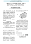
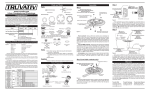
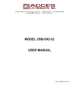
P1.18 Owner's manual Contents Introduction Foreword......................... 4 Symbols......................... 4 Technical Data Development................... 7 Tightening torques........... 7 Safety Intended use................... 8 Basic safety instructions... 8 Riding Before every ride........... 10 Shifting correctly........... 11 Installation work Installing rotary shifter... 12 Installing or replacing . the derailleur cable........ 13 Installing Pinion chain tensioner...................... 22 Adjusting chain tension (Pinion chain tensioner).. 23 Replacing chain ring...... 24 Chain length . & chain tension............. 26 Installing transmission... 27 Maintenance work Frequency..................... 28 Adjusting shifting.......... 29 Oil change.................... 30 Legal information Liability........................ 31 3 Introduction Foreword You are now the owner of a modern Pinion bicycle transmission – made in Germany. This owner's manual is a part of your Pinion product and contains information on how to operate, adjust, install and maintain your product safely. Read this manual carefully before using your Pinion product. Always observe and follow all instructions in this manual – and also the user instructions from other manufacturers whose products are used on your bicycle (chain, wheels, quick release skewers etc.). Remember that the mechanic is responsible for the suitability and compatibility of all components that interact with your Pinion product. Symbols ))The pointing finger prompts you to carry out an action. ÎÎ The arrow shows results or requirements. LLThis instruction gives you additional information or tips. This instruction warns of a hazardous situation, which if not avoided may result in death or serious injury. This instruction warns of a hazardous situation, which if not avoided may result in minor or moderate injury. This instruction warns of potential material damage. If the instructions in this manual are not observed, this may result in accidents with fatal consequences or serious injury. 4 This instructions warns of potential environmental damage. P1.18 Introduction Keep this manual for other users of your Pinion product. Make sure that every user reads, understands and observes this manual. If you ever sell or give away your Pinion product, give this manual to the new owner. The illustrations in this manual may be different from your Pinion product, but the required work steps are the same for all models and variants – unless otherwise specified. The type name of your Pinion bicycle transmission is stamped on the left side of the transmission above the transmission cover (fig. 1). Please note that the transmission will have a different feel compared to a chain transmission. Familiarize yourself with your new Pinion bicycle transmission and the differences in your transmission during your initial rides. See www.Pinion.eu for many more tips and more information on your Pinion product. 1 We wish you all the best with your leisure and competitive riding. The P inion Team 5 Technical Data D C E A B F P1.18 Type name Chainline (A) Q-factor (B) mm Crank length* (C) Crank hub Chain ring* (D) Thickness, chain ring (E) Dimension, chain (F) Teeth mm Gears via rotary shifter Gear ratio, total Gear steps, constant % Ratio in 1st gear (at 21:24) Ratio in 18th gear (at 21:24) * optional ** additional chains approved by Pinion – see www.pinion.eu ***Rider + backpack etc. 6 Oil volume/type Rider weight max.*** 2 ml (oz) kg (lb) 54 174 175 / 170 Pinion Standard 24 2 6.6 – 6.8 (9-speed)** 18 636 ~ 11.5 1.59 0.25 60 (2.0) / Pinion 110 (243) P1.18 Technical Data m (ft) 11,5 9,0 (29.5) 8,0 (26.2) 7,0 (23.0) 6,0 (19.7) 5,0 (16.4) 4,0 (13.1) 3,0 (9.8) 2,0 (6.6) 1,0 (3.3) 1,3 (4.3) 1,5 (4.9) 1 2 1,6 (5.2) 1,8 (5.9) 3 4 2,5 (8.2) 2,8 (9.2) 2,0 (6.6) 2,2 (7.2) 5 6 Development 7 8 3,1 (10.2) 9 3,4 (11.2) 10 3,8 (12.5) 11 12 4,8 (15.7) 13 14 6,0 (19.7) 15 6,6 (21.7) 16 7,4 (24.3) 17 8,3 (27.2) 18 3 Tightening torques LLThe specified values in m (ft) per crank revolution c orrespond to the recommended ratio for sprocket (back) : chain ring (front) 21 : 24 = 0.875.. The calculation (fig. 3) is based on tire size 26×2.2 (55-559).. . You can find an Excel™ table for calculating your individual ratio at www.pinion.eu. 4,3 (14.1) 5,4 (17.7) % Tightening torque in N·m (lbf·in) max. Transmission retaining screws Central crank screws Crank clamp screws Chain ring lock ring Shift box housing screws Rotary shifter clamp screws Rotary shifter cover housing screws Cable clamp screws Oil screw plug 10 (89) 10 (89) 6 (53) 30 (266) 1.5 (13) 1 (9) 0.25 (2) 0.25 (2) 3 (27) with threadlocker dry with threadlocker greased dry dry dry dry dry 7 Safety Intended u se Basic safety instructions Always remember that cycling can be dangerous for the rider and other people and also for the bicycle and its components. Accidents Use other than as intended may cause accidents resulting in death or seresulting in death or serious injury may happen even with the best rious injury. protective equipment and all required safety devices. Pinion bicycle transmissions are designed and intended exclusively Use your common sense and avoid dangerous actions. –– for installation on bicycle frames designed for the purpose with Installation & maintenance rigid rear triangle and a transmission bracket in the area of the bottom bracket. A transmission damaged as a result of faulty or non-approved installation –– for installation on bicycle frames designed for the purpose with may cause an accident. suspension rear triangle and a transmission bracket in the area of –– Don't overestimate your technical ability. Have all installation and the bottom bracket - and, if necessary, in combination with a suitmaintenance work done by a specialist workshop for bicycles. That able chain tensioner system that compensates for the distance is the only way to be sure that the work is done correctly. between the chain ring and sprocket that varies with the move–– Installation work that is not described in this owner's manual (e. g. ment of the suspension. opening the transmission, etc.) must be done exclusively by a –– for use with a single-gear rear freewheel hub without a back pedal specialist workshop authorized by Pinion or by the Pinion company brake*. itself.. –– for use with a rear cassette freewheel hub with spacers for setting Do not attempt work of this type yourself – you will not only the correct chainline. endanger your own health but you may be exposed to liability –– for use with a suitable chain tensioner system. claims. –– for the maximum approved rider weight – see Technical Data, page 6. –– Never modify your Pinion product in any way (e. g. grinding, drilling, painting, etc.). Pinion bicycle transmissions must never be used in combination with –– Always use a torque wrench designed for the required torque at a rigid single gear rear wheel hub! installation steps that require a specific tightening torque. –– Keep your bicycle in good technical condition at all times. * A back pedal brake cannot be used with the freewheel integrated in the transmission. 8 Unsuitable accessories and additional components may cause accidents. –– Use original Pinion parts and lubricants exclusively. –– Use a rear wheel quick release system that reaches the required closing pressure of at least 4000 N exclusively. It is best to use a rear wheel hub that is permanently fastened with axle nuts in the rear triangle. P1.18 Safety –– Use exclusively a bicycle chain with a width of 6.6 – 6.8 mm (9-s) or any other chain approved by Pinion (see www.pinion.eu) and an appropriately sized sprocket. Riding Component failure may cause accidents. –– Before every ride make sure that the quick release system of your wheels is correctly installed and that your wheels cannot be accidentally released. –– Before every ride make sure your brakes are operating correctly and the brake pads are not excessively worn. –– Before every ride make sure your chain is correctly tensioned. –– Never exceed the maximum approved rider weight – see Technical Data, page 6. –– Never ride with your Pinion bicycle transmission if damage (to the transmission housing, cranks, etc.) is visible, unusual noises can be heard, or you have any doubts about the transmission. In this case have your Pinion bicycle transmission checked by a specialist workshop for bicycles. –– Do not ride with your Pinion bicycle transmission in temperatures below -15 ° (5 °F) or above 40 °C (104 °F). Incorrect riding behaviour or improper equipment may cause accidents. –– Always obey the traffic regulations of the country where you are riding your bicycle (lights, reflector, etc.) and also the regulations governing off-road mountain biking. –– Always wear a good-quality, undamaged bicycle helmet (e.g. ANSIcertified) and clothing that is close-fitting but does not hinder movement. –– Ride your bicycle only when you are in good physical condition and your bicycle and all its components are in good condition. 9 Riding Before every ride Component failure may cause accidents. –– Before every ride make sure that the quick release system of your wheels is correctly installed and that your wheels cannot be accidentally released. –– Before every ride make sure your brakes are operating correctly and the brake pads are not excessively worn. –– Before every ride make sure your chain is correctly tensioned. –– Never ride with your Pinion bicycle transmission if damage (to the transmission housing, cranks, etc.) is visible, unusual noises can be heard, or if you have any doubts the condition of the transmission. Have your Pinion bicycle transmission checked by a specialist workshop for bicycles. A chain that continues to rotate because the sprocket or rear wheel hub does not move easily during freewheel may cause an accident. –– Before every ride make sure that sprocket and rear wheel hub freewheel smoothly. Rotate the crank backwards – the chain must not move with the sprocket and rear wheel hub during freewheel. 10 P1.18 Riding Shifting correctly LLThe mark (1) on the fixed part of the rotary shifter shows the selected gear (fig. 4). LLYou can shift through several gears with one movement (e.g. from 06 to 02). You cannot shift directly from 01 to 18 or from 18 to 01. 1 LLYou can shift at a standstill or with the crank rotating backwards and this protects the transmission. LLDownshifting (18–17–16– … –01) under load is possible to a limited extent. To protect the transmission, the shift is not executed if the pressure on the crank or pedal is too high – e.g. during out of the saddle pedaling. LLA mechanism in the transmission allows upshifts (01–02–03– … –18) under load. This is possible during all shifts, except when shifting from 06 to 07 and from 12 to 13. At these points the pressure on the pedal must be momentarily released. 4 LLYou may hear a more or less unobtrusive clicking sound in gears 07 and 13. This is normal and there is no reason for concern. ))Always reduce the pressure on the pedal during downshifts . (18–17–16– … –01). ))When shifting up from 06 to 07 and from 12 to 13 always release the pressure on the pedal. 11 Installation work Installing rotary shifter Incorrect installation may restrict braking and steering and cause accidents. –– Make sure that the position of the rotary shifter does not interfere with the full range of operation of the brake lever. –– Make sure that the derailleur cables do not interfere with the handlebar movement. Incorrectly mounted handlebars may fail and cause an accident. –– Make sure that the clamp ring (1) is present, the clamp screws (2) do not act directly on the handlebar surface (fig. 6). –– Always follow the manufacturer's directions for carbon handlebars. 3 4 5 LLThe Pinion rotary shifter is generally correctly positioned in the adjusting screws (3) with the derailleur cable pointing down and slightly forward – i.e. in the 4–5 o'clock direction (fig. 5). In this position you can best see the current gear and the derailleur cables do not interfere with the brake lever. LLIn the event of a fall it is advantageous if the brake lever and rotary shifter 1 can twist. This reduces the danger of irreparable damage – including the handlebar. Tighten the clamp screws of the brake lever and rotary shifter just tight enough so they cannot be twisted by hand. 2 ))Use carbon mounting paste on the clamp area for carbon handlebars. ))Attaching rotary shifter to the handlebar. ))Attach rotary shifter (4) and if applicable bar end to the handlebar (fig. 5). ))Push rotary shifter onto the handle of the handlebar to the stop and rotate to the correct position. ))Tighten the two clamp screws (2) alternately in stages – do not exceed the maximum tightening torque of 1 N·m (9 lbf·in) under any circumstances (fig. 6). 2 mm 1 N·m (9 lbf·in) max. 12 ÎÎ This completes the installation of the rotary shifter. 6 P1.18 Installation work 8 mm 1 5 2 0,25 N·m (2 lbf·in) max. 4 Installing or replacing the derailleur cable LLYour Pinion bicycle transmission is operated with one pulling cable – even though it appears at first glance to have two derailleur cables. The clamps for both pulling cable ends are in the rotary shifter. You can order the prepared long pulling cable directly from Pinion.. If you wish to use your own pulling cable, always use one with the following dimensions: Ø 1.2 mm /length 3000 mm. An end nipple is not necessary. ))Unscrew the housing screws (1) of the cover (2) on the rotary shifter. ))Remove the cover. 7 LLThe clamp screws are easily accessible at rotary shifter positions 01 and 18. ))Slacken clamp screws (3) – 2× per cable end. ))Pull the ends of the pulling cable out of the rotary shifter. ))Hold the adjusting screws (4) in position and slacken the lock nuts (5) (fig. 7). ))Screw the lock nuts to the stop on the heads of the adjusting screws. ))First, screw in adjusting screws completely – then unscrew three revolutions. ÎÎ This ensures an adequate adjustment range for subsequent adjustments of the transmission. 3 1,5 mm 0,25 N·m (2 lbf·in) max. 8 13 Installation work ))Unscrew the housing screws (6) of the transmission cover (7). ))Remove the transmission cover. 6 7 2,5 mm 1,5 N·m (13 lbf·in) max. 9 ))Remove the pulling cable helix (8) with the cable from the transmission housing. ))Make sure that the PTFE sealing ring (9) is correctly seated in the transmission housing. ))Remove the pulling cable from the pulling cable helix. 9 8 14 10 P1.18 Installation work ))Hold crank and chain ring in position. ))Rotate sun gear (10) clockwise to the stop with a 3 mm Allen wrench. X× CLIC ÎÎ 1st gear is engaged. 10 ST OP P 11 ))Hold crank and chain ring in position. ))Rotate sun gear (10) 8 clicks counterclockwise with 3 mm Allen wrench. 8× CLIC ÎÎ 9th gear is engaged. 10 12 15 Installation work ))Insert new pulling cable through the hole in the pulling cable helix. ))Leave the pulling cables hanging with equal lengths (fig. 13). = 13 ))Wind the pulling cable ends ¾ revolution around the pulling cable helix (fig. 14). ))Press the pulling cable at the bends into the guide of the pulling cable helix with a small screwdriver. ))Hold the pulling cable with the pulling cable helix with one hand so the pulling cable cannot unwind. 14 16 P1.18 Installation work ))Insert the ends of the pulling cable through the holes in the transmission housing (fig. 15). ))Maintain tension on the ends of the pulling cable. 15 ))Make sure that the PTFE sealing ring (9) is correctly seated in the transmission housing (fig. 10). Insert pulling cable helix into the transmission housing (fig. 16). )) ))Make sure that the insertion hole of the pulling cable helix is centrally positioned between the transmission housing holes. ))Maintain tension on the ends of the pulling cable. 16 17 Installation work ))Keep the left end of the pulling cable under tension (fig. 17). ))Rotate the sun gear (10) 8 clicks clockwise or to the stop with a 3 mm Allen wrench. gear is engaged. ))Insert the left end of the pulling cable through the outer sleeve of the derailleur cable. ÎÎ 1st 10 8× CLIC 17 18 P1.18 Installation work ))Switch rotary shifter to position 01 (fig. 18). 18 ))Insert the left end of the pulling cable into the internal– towards the center of the handlebar – adjusting screw (11), rotary shifter housing and clamp (12). ))Keep the left end of the pulling cable under tension (fig. 19). 1,5 mm 0,25 N·m (2 lbf·in) max. ))Make sure that the ends of the derailleur cable outer sleeve are firmly in the stops on the adjusting screw and transmission housing. ))Tighten the two clamp screws alternately to a tightening torque of 0.25 N·m (2 lbf·in). 12 ))Cut the left end of the pulling cable as close as possible to the clamp with a sharp wire cutter. 11 19 19 Installation work ))Rotate rotary shifter clockwise (01–02–03– … –18) to position 18 (fig. 20). 20 ))Insert the right end of the pulling cable through the outer sleeve of the derail- 13 leur cable. ))Insert the right end of the pulling cable through the outer adjusting screw towards the end of the handlebar (13), rotary shifter housing and clamp (14). ))Keep the right end of the pulling cable under tension (fig. 21). ))Make sure that the end of the derailleur cable outer sleeve are firmly in the stops on the adjusting screw and transmission housing. ))Tighten the two clamp screws alternately to a tightening torque of 0.25 N·m (2 lbf·in). 14 ))Cut off the right end of the pulling cable as close as possible to the clamp with a sharp wire cutter. 1,5 mm 0,25 N·m (2 lbf·in) max. 20 21 P1.18 Installation work ))Position cover (2). ))Tighten housing screws (1) to a tightening torque of 0.25 N·m (2 lbf·in). 1 ))Test shifting function, if necessary adjust cable tension with the adjusting screws – see Adjusting shifting, page 29. 2 0,25 N·m (2 lbf·in) max. 22 ))Position transmission cover (7). ))Tighten housing screws (6) to a tightening torque of 1.5 N·m (13 lbf·in). ÎÎ The 6 2,5 mm 1,5 N·m (13 lbf·in) max. replacement of the derailleur cable is complete. 7 23 21 Installation work Installing Pinion chain tensioner If a chain tensioner fails because of improper use, it may cause an accident. The Pinion chain tensioner is designed and intended exclusively for use with a Pinion bicycle transmission. –– Always install the Pinion chain tensioner on the retaining positions on your Pinion bicycle transmission only. LLThe Pinion chain tensioner can be mounted on your Pinion bicycle transmission in one of two different positions: A or B (fig. 24). 1 4 mm 4 N·m (35 lbf·in) max. The selection of the correct position depends on the installation position selected by the manufacturer of your bicycle for the Pinion bicycle transmission.. Make sure that your Pinion chain tensioner transfers the tension effect in full to your bicycle chain in the position that you select, but also cannot contact the chain stay or tire of your bicycle at any position. 24 ))Remove chain. ))Remove crank and chain ring – see Replacing chain ring, page 24. ))Tighten retaining screws (1) to a tightening torque of 4 N·m (35 lbf·in). ))Install crank and chain ring – see Replacing chain ring, page 24. ))Position chain and guide it through the tension mechanism (fig. 25). ))Connect chain. LLYour chain has the correct length if the tension mechanism of the chain tensioner is pretensioned (2), but can still be moved upwards (3) (fig. 25). ÎÎ The Pinion chain tensioner is installed. 3 2 22 25 P1.18 Installation work Adjusting chain tension (Pinion chain tensioner) LLIf your chain frequently hits the chain stay on your bicycle frame, it may be necessary to increase the chain tension.. If the chain or cranks continue to rotate although the rear wheel freewheel operates correctly, or if the chain tensioner rattles, it may be necessary to reduce the chain tension. 3 ))Remove chain and remove it from the chain ring and sprocket. ))Disconnect the spring leg (1) at the tension mechanism (2). ))Rotate the tension mechanism forward. ))The screw (3) of the spring shaft is accessible. 1 2 4 N·m (35 lbf·in) max. 26 ))Unscrew the screw (3) of the spring shaft (4). ))Move the spring end pin (5) counterclockwise (+). 5 ÎÎ The chain tension is increased. ))Make sure that the square head of the spring shaft is in the same position in its opening in the base plate (6) as before. ))Screw in the screw (3) of the spring shaft (4) and tighten to a tightening torque 6 4 of 4 N·m (35 lbf·in). ))Position the chain on the chain ring and sprocket. ))Attach spring leg (1) to tension mechanism. ))Check the setting and repeat the procedure if necessary. 3 1 2 4 N·m (35 lbf·in) max. 27 23 Installation work 10 mm 10 N·m (89 lbf·in) max. Replacing chain ring LLIf you need to replace the chain ring of your Pinion bicycle transmission (be- cause of wear, different gear ratio), you can order it and the required tool directly from us.. See www.pinion.eu for a selection of different chain rings. LLAnother method of changing the gear ratio is to replace the sprocket on your 2 rear wheel. LLChain ring, sprocket and chain always wear on opposite sides during use. This means that the drive stop working without problems (chain disengages, more noise) if only one of these parts is replaced.. We recommend replacing all three parts if one needs replacing. 1 2 ))Remove chain. 4 mm 6 N·m (53 lbf·in) max. 28 ))Unscrew center screw (1). ))Slacken both clamp screws (2) on the crank. ))Pull the crank from the input shaft. ))Hold chain ring with chain whip. ))Unscrew lock ring (3) clockwise (left-hand thread) with the Pinion lock ring tool (4). 3 ))Remove chain ring 4 mm 3 ½" 30 N·m (266 lbf·in) max. 24 29 P1.18 Installation work ))Make sure that the gears (5) and contact surfaces on the transmission side and the chain ring (6) and lock ring (3) are clean and free from old grease. ))Lightly grease gears (5). 5 6 ))Hold chain ring with chain whip. ))Install chain ring. ))Lightly grease contact area and thread of lock ring (3). ))Screw in lock ring counterclockwise (left-hand thread) with the Pinion lock ring tool (4). 3 4 ))Hold chain ring with chain whip. ))Tighten lock ring (3) to a tightening torque of 30 N·m (266 lbf·in). ))If necessary, install new chain – see Chain length & chain tension, page 26. ½" 30 N·m (266 lbf·in) max. 30 10 mm 10 N·m (89 lbf·in) max. LLTo protect the gears (7) on the input shaft and cranks from one-sided loads, it is a good idea to remove both cranks regularly (1× a year) and to replace them offset by 1–2 teeth and with fresh grease. ))Make sure that the gears (7) on the input shaft and crank are clean and free 7 from old grease. ))Lightly grease gears. ))Position crank and push it manually on the input shaft to the stop – do not use any impact tools (hammer etc.). 7 ))Screw in center screw (1) and tighten to a tightening torque of 10 N·m 2 (89 lbf·in). ))Tighten the two clamp screws (2) in stages and alternately until both screws 1 3 4 mm 6 N·m (53 lbf·in) max. have reached a tightening torque of 6 N·m (53 lbf·in). ÎÎ The 2 chain ring has been replaced. 31 25 Installation work Chain length & chain tension LLThe correct length of your bicycle chain depends on various factors: ··The number of teeth on the sprocket and chain ring – after replacement it may be necessary to reset the chain tension. ··Suspension travel and type of spring rear hub of your bicycle frame – follow the manufacturer's instructions. ··Type of chain tensioner or tensioning system (horizontal dropout ends with clamp screws) – follow the manufacturer's instructions. LLThe basic rule for the length of your bicycle chain is as short as possible and as long as necessary. The function and adjustment range of your chain tensioner and the complete suspension of the rear triangle must not be impaired. ~ 10–15 mm 26 32 Accelerated wear of the complete drive because of excessively high chain tension. –– For direct tension (horizontal dropouts with clamp screws) make sure that the chain has approx. 10–15 mm play (fig. 32). P1.18 Installation work Installing transmission Incorrect installation may distort and damage the transmission. –– Make sure that all four key sleeves (1) (fig. 33/34) are installed flat in their seats in the transmission housing – if necessary, press in with a parallel pressing tool (e.g. screw clamp, suitable clamp, etc.) (fig. 33). –– Follow the sequence and tightening torque (fig. 34). 1 33 ))Make sure that all contact points between the transmission and bicycle frame 1. bridge are clean. ))Apply fresh screw locking fluid (medium) to the transmission retaining screws. 3. 6. 1 ))Position transmission in the bicycle frame bridge. ))Position all screws. ))Tighten screws in the specified sequence (fig. 34) to a tightening torque of 10 N·m (89 lbf·in). 5. ÎÎ The transmission is installed. 2. 3T30 mm 10 N·m (89 lbf·in) max. 4. 34 27 Maintenance work Frequency LLThe frequency of use and weather conditions determine the frequency of maintenance work on your Pinion bicycle transmission.. Carry out the following maintenance operations more frequently if you use your bicycle under extreme conditions (rain, dirt, long distances, etc.). Corrosion and material damage by penetration of water. –– Never use a pressure cleaner or steam cleaner to clean your bicycle - the seals in the bicycle components cannot withstand this pressure. –– Be careful even if you use an ordinary hose. Never direct a spray of water directly at the area of a seal (fig. 35). ))Clean the transmission housing with water, detergent and a brush. ))Clean the chain, chain ring, sprocket and, if necessary, the roller of the chain 35 tensioner. ))Oil the chain lightly. ))Check that all screw fasteners have the required tightening torque and adjust if necessary. ))Check the tension and smoothness of the derailleur cable – see Adjusting shifting, page 29. ))Check chain tension – see Chain length & chain tension, page 26. ))Adjust chain tension if necessary – see Adjusting chain tension (Pinion chain tensioner), page 23. ))Check that the chain tensioner rollers move smoothly and inspect for wear (excessive play, loud running noises) – replace rollers if necessary (fig. 36). 2 N·m (18 lbf·in) max. 28 36 P1.18 Maintenance work Adjusting shifting LLYour Pinion bicycle transmission is correctly adjusted if . 1 3 8 mm 2 1 4 2 it shifts immediately (cable tension), . all 18 gears can be selected with minimum force (cable tension), . the display on the rotary shifter matches the selected gear (synchronization). ))Hold adjusting screws (1) (2) and slacken lock nuts (3) (fig. 37). Adjusting cable tension LLThe cable tension is in the correct range if the ends of the derailleur cable outer sleeves are within the stops on the transmission and rotary shifter without play and are not under tension. ))Unscrew both adjusting screws ¼ revolution counterclockwise (+). ÎÎ Cable tension is increased. ÎÎ Force required is increased. or: )Screw in both adjusting screws ¼ revolution clockwise (-). 37 ) ÎÎ Cable tension is reduced. ÎÎ Shift is less immediate. Synchronizing position of rotary shifter ))Shift rotary shifter clockwise (01–02–03– … –18) to the stop towards position 18 (fig. 38). ))Check that the symbol for position 18 is centrally placed beside the mark (4). ))Screw in adjusting screw (1) ¼ revolution clockwise (-). Unscrew adjusting screw (2) ¼ revolution counterclockwise (+). ÎÎ The rotary shifter scale moves counterclockwise (towards position 17). or: ))Unscrew adjusting screw (1) ¼ revolution counterclockwise (+). Screw in adjusting screw (2) ¼ revolution clockwise (-). ÎÎ The rotary shifter scale moves counterclockwise (towards position 01). 38 ))Check setting and repeat procedure if necessary. ))Hold adjusting screws (1) (2) and tighten lock nuts (3) to a tightening torque of 2–3 N·m (18–27 lbf·in) (fig. 37). 29 Maintenance work Oil change LLEvery 10 000 km (6 200 miles) or 1× per year the oil in your Pinion bicycle transmission must be changed.. Use original Pinion gear oil exclusively.. Fill volume – see Technical Data, page 6. Dispose of used lubricants and oils correctly and in accordance with the applicable regulations – never dispose of waste in the sewage system or in the ground. 1 2 2,5 mm 1,5 N·m (13 lbf·in) max. ))Unscrew housing screws (1) of the transmission cover (2). ))Remove the transmission cover. 39 ))Unscrew the screw plug (3) in the filler opening. ))Have a drainage tray ready. ))Place bicycle on its side. ))Drain used oil completely from the filler opening into the drainage tray. ))Place the bicycle upright or replace on repair stand. ))Add fresh oil, fill volume – see Technical Data, page 6. ))Replace screw plug (3) in filler opening and tighten to a tightening torque of 3 N·m (27 lbf·in). ))Position cover (2). ))Tighten housing screws (1) to a tightening torque of 1.5 N·m (13 lbf·in). 3 ÎÎ The 3 mm 3 N·m (27 lbf·in) max. 30 oil change is complete. 40 P1.18 Legal information Liability The legal liability requirements apply for damage to material and workmanship. The liability period starts on the date of initial purchase. This does not include components that are subject to normal wear (e. g. shift cable with external sleeve). Damage caused by improper use, unintended use or improper installation or maintenance is not included. We also do not accept liability for immediate or consequential damages arising from negligence. LLIn case of damage, first contact the dealer from which you urchased your Pinion product.. p The dealer will contact the bicycle manufacturer, distributor or us directly to discuss the procedure on your behalf.. Do not return a defective Pinion product directly to us without prior consultation. 31 Pinion GmbH Heerweg 15 A 73770 Denkendorf phone +49 711 217 491-51 fax +49 711 217 491-79 [email protected] www.pinion.eu © Pinion GmbH 2012 All rights reserved. Printed in Germany. 07-2012 Umschlag & Inhalt:. www.technische-redaktion.de