1
SERIES IP521 INDUSTRIAL I/O PACK
EIA/TIA-422B SERIAL COMMUNICATION MODULE
___________________________________________________________________________________________
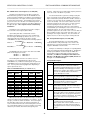
Table 3.1 Continued: IP521 I/O Memory Map
Base
MSB
LSB
LCR
Addr+
D15
D08 D07
D00
0C
R/W - MSR
Not Driven1
Port A Modem
N/A
Status Reg.
0C
R/W - Xoff-1
BF
Not Driven1
Low Byte
Hex
0E
R/W - SCR
Not Driven1
Port A Scratch
N/A
Pad, Interrupt
Vector, FIFO Count
0E
R/W - Xoff-2
BF
Not Driven1
High Byte
Hex
Port B Registers
10
1
Organized as Port A3
↓ Not Driven
1E
Port C Registers
20
1
Organized as Port A3
↓ Not Driven
2E
Port D Registers
30
1
Organized as Port A3
↓ Not Driven
3E
Port E Registers
40
1
Organized as Port A3
↓ Not Driven
4E
Port F Registers
50
1
Organized as Port A3
↓ Not Driven
5E
Port G Registers
60
1
Organized as Port A3
↓ Not Driven
6E
Port H Registers
70
1
Organized as Port A3
↓ Not Driven
7E
RBR - Receiver Buffer Register, Ports A-H (READ Only)
Base
Addr+
The Receiver Buffer Register (RBR) is a serial port input data
register that receives the input data from the receiver shift
register. Note that the RBR will only receive data if the
transceiver is first enabled to receive data. The transceiver is
enabled to receive data by setting bit-0 of the MCR (Modem
Control Register) to a logic “1”.
0D
0D
The RBR holds from 5 to 8 bits of data, as specified by the
character size programmed in the Line Control Register (LCR bits
0 & 1). If less than 8 bits are transmitted, then data is rightjustified to the LSB. If parity is used, then LCR bit 3 (parity
enable) and LCR bit 4 (type of parity) are required. Status for the
receiver is provided via the Line-Status Register (LSR). When a
full character is received (including parity and stop bits), the datareceived indication bit (bit 0) of the LSR is set to 1. The host
CPU then reads the Receiver Buffer Register, which resets LSR
bit 0 low. If the character is not read prior to a new character
transfer between the receiver shift register and the receiver buffer
register, the overrun-error status indication is set in LSR bit 1. If
there is a parity error, the error is indicated in LSR bit 2. If a stop
bit is not detected, a framing error indication is set in bit 3 of the
LSR.
0F
0F
11
↓
1F
21
↓
2F
31
↓
3F
41
↓
4F
51
↓
5F
61
↓
6F
71
↓
7F
Serial asynchronous data is input to the receiver shift register
via the receive data line (RxD). From the idle state, this line is
monitored for a high-to-low transition (start bit). When the start
bit is detected, a counter is reset and counts the 16x clock to 71/2 (which is the center of the start bit). The start bit is judged
valid if RxD is still low at this point. This is known as false startbit detection. By verifying the start bit in this manner, it helps to
prevent the receiver from assembling an invalid data character
due to a low-going noise spike on RxD. If the data on RxD is a
symmetrical square wave, the center of the data cells will occur
within ±3.125% of the actual center (providing an error margin of
46.875%). Thus, the start bit can begin as much as one 16x
clock cycle prior to being detected.
Notes (Table 3.1):
1. The upper 8 bits of these registers are not driven. Pullups
on the carrier data bus will cause these bits to read high
(1’s).
2. All Reads/Writes to IO space are 1 wait state, Interrupt
select cycle is 2 wait states, and ID space reads are 0 wait
states.
3. To save user manual space the registers corresponding to
ports B to H have not been individually shown. The
registers of ports B to H are in the address space shown
above. To access a register in port H, for example, the
offset of 70 hex is added to the address of the
corresponding register given in table 3.1. All ports require a
16 byte memory block.
THR - Transmitter Holding Register, Ports A-H (WRITE Only)
The Transmitter Holding Register (THR) is a serial output
data register that shifts the data to the transmit data line (TxD).
However, the THR data will not pass to the TxD line unless the
tranceiver is first enabled. The transceiver must be enabled to
transmit data by setting bit-1 of the MCR (Modem Control
Register) to a logic “1”.
The Transmitter Holding Register (THR) is a serial port output
data register that holds from 5 to 8 bits of data, as specified by
the character size programmed in the Line Control Register. If
less than 8 bits are transmitted, then data is entered right-justified
to the LSB. This data is framed as required, then shifted to the
transmit data line (TxD). In the idle state, TxD is held high. In
Loopback Mode, this data is looped back into the Receiver Buffer
Register.
This board operates in two different modes. In one mode,
this device remains software compatible with the industry
standard 16C450 family of UART’s and provides double-buffering
of data registers. In the FIFO Mode (enabled via bit 0 of the FCR
register), data registers are FIFO-buffered so that read and write
operations can be performed while the UART is performing serialto-parallel and parallel-to-serial conversions. Two FIFO modes
are possible: FIFO Interrupt Mode and FIFO Polled Mode. Some
registers operate differently between the available modes and this
is noted in the following paragraphs.
The status of the THR is provided in the Line Status Register
(LSR). Writing to the THR transfers the contents of the data bus
(D7-D0) to the THR, provided that at least one FIFO location is
available. The THR empty flag in the LSR register will be set to a
logic 1 when at least one FIFO location is available.
-7-