1
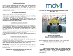
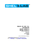
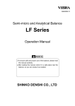
WATERJACKET CO2 INCUBATORS WITH MICROPROCESSOR CONTROL SCO5W SCO5W-2 SCO10W SCO10W-2 Previously designated 3517 3517-2 3524 3524-2 INSTALLATION AND OPERATION MANUAL 12/2013 4861607 Sheldon Manufacturing Inc. P.O. Box 627 Cornelius, Oregon 97113 EMAIL: [email protected] INTERNET: http://www.Shellab.com/~Shellab 1-800-322-4897 (503) 640-3000 FAX (503) 640-1366 TABLE OF CONTENTS SECTION 1.0 RECEIVING AND INSPECTION SECTION 2.0 GRAPHIC SYMBOLS SECTION 3.0 INSTALLATION SECTION 4.0 CONTROL PANEL OVERVIEW SECTION 5.0 OPERATION SECTION 6.0 DATA LOGGER FUNCTION SECTION 7.0 FYRITE CO CHECKING SECTION 8.0 HEPA C02 FILTER SECTION 9.0 MAINTENANCE SECTION 10.0 TROUBLESHOOTING SECTION 11.0 PARTS LIST UNIT SPECIFICATIONS SCHEMATICS These units are CO Water Jacketed incubators for professional, industrial or educational use where the preparation or testing of materials is done at approximately atmospheric pressure and no flammable, volatile or combustible materials are being heated. These units are not intended for hazardous or household locations or use. 2 INTRODUCTION Thank you for choosing a water jacket incubator. These units are not intended for use at hazardous or household locations. Before you use the unit, read this entire manual carefully to understand how to install, operate, and maintain the unit in a safe manner. Your satisfaction with the unit will be maximized as you read about its safety and operational features. Keep this manual on-hand so it can be used by all operators of the unit. Be sure all operators of the unit are given appropriate training before you put the unit in service. Note: Use the unit only in the way described in this manual. Failure to follow the guidelines and instructions in this manual may be dangerous and illegal. General Safety Considerations Your incubator and its recommended accessories have been designed and tested to meet strict safety requirements. For continued safe operation of your incubator, always follow basic safety precautions including: Read this entire manual before using the incubator. Be sure you follow any city, county, or other ordinances in your area regarding the use of this unit. Use only approved accessories. Do not modify system components. Any alterations or modifications to your incubator may be dangerous and will void your warranty. Always plug the unit’s power cord into a grounded electrical outlet that conforms to national and local electrical codes. If the unit is not grounded, parts such as knobs and controls may conduct electricity and cause serious injury. Do not connect the unit to a power source of any other voltage or frequency beyond the range stated on the power rating on the dataplate inside the door of the unit. Do not modify the power cord provided with the unit. If the plug does not fit an outlet, have a proper outlet installed by a qualified electrician. Avoid damaging the power cord. Do not bend it excessively, step on it, place heavy objects on it. A damaged cord can easily become a shock or fire hazard. Never use a power cord after it has become damaged. Do not position the equipment in such a manner as to make it difficult to disconnect power cord or coupler. Do not attempt to move the unit while in operation or before the unit has been allowed to cool. 3 1 Section RECEIVING AND INSPECTION IMPORTANT: READ THIS INSTRUCTION MANUAL IMMEDIATELY! Your satisfaction and safety require a complete understanding of this unit, including its proper function and operational characteristics. Be sure operators are given adequate training before attempting to put the unit in service. NOTE: This equipment must be used only for its intended application; any alterations or modifications will void your warranty. 1.1 Inspection: The carrier, when accepting shipment, also accepts responsibility for safe delivery and is liable for loss or damage claims. On delivery, inspect for visible exterior damage, note and describe on the freight bill any damage found and enter your claim on the form supplied by the carrier. 1.2 Inspect for concealed loss or damage on the unit itself, both interior and exterior. If any, the carrier will arrange for official inspection to substantiate your claim. Save the shipping crate until you are sure the unit has been delivered in good condition. 1.3 Return Shipment: If for any reason you must return the unit, contact your customer service representative for authorization and supply nameplate data. For information on where to contact Customer Service please see the manual cover. 1.4 Accessories: Make sure that all of the equipment indicated on the packing slip is included with the unit. Carefully check all packaging before discarding. Each chamber comes equipped with 3 shelves, 6 slides, 1 humidity pan and a power cord. 4 2 Section GRAPHIC SYMBOLS Your incubator has been provided with a display of graphic symbols which is designed to help in identifying the use and function of the available user adjustable components. 2.1 Indicates that you should consult your manual for further description or discussion of a control or user item. 2.2 Indicates "Temperature". 2.3 Indicates "Over-temperature safety". 2.4 C Indicates "Degrees Centigrade". 2.5 CO2 Indicates "Carbon Dioxide". 2.6 Indicates "Gas" (CO2 for this unit). 2.7 Indicates "AC Power ". 2.8 Indicates "Water Jacket Low". 2.9 Indicates "ON/I" and "OFF/O". 2.10 Indicates "Relative Humidity". 2.11 %RH Indicates "Percent Relative Humidity". 2.12 Indicates "Potential Shock Hazard" behind this protective partition. 2.13 Indicates "Protective Earth Ground". 2.14 Indicates “Unit should be recycled” (Not disposed of in land-fill) 5 3 Section INSTALLATION Local city, county, or other ordinances may govern the use of this equipment. If you have any questions about local requirements, please contact the appropriate local agency. Installation may be performed by the end user. Under normal circumstances this unit is intended for use indoors, at room temperatures between 5 and 40C, at no greater than 80% Relative Humidity (at 25) and with a supply voltage that does not vary by more than 10%. The unit’s technical and environmental specifications includes: altitude not exceeding 2000 m operating and Pollution Degree of 2. Customer service should be contacted for operating conditions outside of these limits. CAUTION: Make sure that the incubator is located in its intended position and level before filling the water jacket. Directions for filling the jacket are in Section 5.2. 3.1 Power Source: The unit power requirements are listed on the data plate. PLUG THE UNIT INTO A PROPERLY GROUNDED AND RATED RECEPTACLE OF THE CORRECT STYLE. A separate circuit is recommended for this unit to prevent loss of product due to overloading or circuit failures caused by other equipment. The power supply must be properly grounded (earthed) and correctly sized to match the unit nameplate rating. The supply voltage must match the nameplate voltage within +/- 10%. The US market units are designed for 120 volts @ 60 Hz, 5 Amps. The EU market units are designed for 230 volts @ 50 Hz, 3.5 Amps. If supplied with a detachable cord set, plug the female end into the inlet on the unit and the male plug into the supply. Assure that units requiring fuses have them installed. The fuse is a T type, 10 amp for 120 vol units, 6.3 amp for 230 volt units. This fuse may be at the inlet or a part of the cord set male plug. The unit must be located to easily allow for it to be unplugged or disconnected. 3.2 Location: When selecting a site for the unit, consider conditions which may affect performance, such as heat from steam radiators, ovens, autoclaves, etc. Avoid direct sun, fast-moving air currents, heating/cooling ducts, and high-traffic areas. To ensure air circulation around the unit, allow a minimum of 10cm of clearance between the incubator and surrounding walls, or obstructions to free air flow. 3.3 Lifting / Handling: These units are heavy and care should be taken to use appropriate lifting devices that are sufficiently rated for these loads. Units should only be lifted from their bottom surfaces. Doors, handles and knobs are not adequate for lifting or stabilization. The unit should be completely restrained from tipping during lifting or transport. All moving parts, such as shelves and trays should be removed and doors need to be positively locked in the closed position during transfer to prevent shifting and damage. 3.4 Leveling: The unit must sit level and solidly. Leveling feet are supplied and must be installed in the four holes in the bottom corners of the unit. With the feet installed and the unit standing upright, each foot can be raised by turning it in a counterclockwise direction. Adjust the foot at each corner until the unit stands level and solid without rocking. If the unit must be moved, drain all of the water from the unit and turn the leveling feet in (clockwise) all the way to prevent damage while moving. 3.5 Cleaning: The unit chamber should be cleaned and disinfected prior to use. The operating conditions and appropriate protocol will determine the correct procedure for decontamination. A typical decontamination procedure that is adequate for many situations has been described below. As well, certain steps are listed that will help reduce the likelihood of contamination and the necessity of decontamination. Whatever process is appropriate, it needs to be done on a regularly scheduled basis. Depending on usage and protocol, this may be monthly, quarterly or otherwise. 6 Regardless of the decontamination procedure used, certain precautions will need to be taken: A. B. Always disconnect the unit from the electrical service when cleaning. Assure all volatile or flammable cleaners are evaporated and dry before reconnecting the unit to the power supply. Special care should be taken when cleaning around sensing heads to prevent damage. C. If you use chlorine-based bleaches or abrasive cleaners this will modify the stainless steel interior finish. DO NOT USE hard tools such as metal wire brushes or steel wool. Use nonabrasive cleaners and soft tools such as plastic brushes. D. In the event hazardous material is spilled onto or into the equipment, appropriate decontamination must be carried out. If there is any doubt about the compatibility of decontamination or cleaning agents with parts of the equipment or with material contained, please contact the manufacturer or his agent. No decontamination or cleaning agents should be used which could cause a hazard as a result of a reaction with parts of the equipment or with the material contained in it. TYPICAL DECONTAMINATION PROCEDURE 1. Remove the humidity pan every week and autoclave, or wash with soap and water then disinfect with 70% alcohol solution. Replace in the incubator with fresh, DISTILLED water. 2. Flush the sample port tubing with 70% alcohol solution. Replace any lines that have a green color. 3. Remove the door gaskets, clean and disinfect. Clean and disinfect all mounting grooves for the door gaskets. 4. Remove all shelves, shelf supports, shelf standards and shields. Autoclave, or wash and disinfect as described in item 1. 5. Wash and disinfect all interior surfaces. 6. Give special attention to cleaning and disinfecting all access ports, air bleeds, shaft holes, electrical pass-through and any other passages into the chamber. 7. Replace all air and CO2 filters every six months or when noticeably dirty on the upstream side. CO2 filters are located in the shadow box just behind the GAS IN fitting and in line with the CO2 tubing kit. Units with flow meters require operator- supplied air pumps. These pumps should be checked for proper air filtering. OPERATION FOR MINIMIZING CONTAMINATION 1. Keep the outside of the incubator, including the air in the laboratory, as clean as possible. This is particularly important for units placed directly on the floor. Do not place incubators near doors, air vents or other areas of high air movement or traffic. 2. The floor around the unit needs to be clean. Units that are placed on the floor should be mounted higher – typically on a caster platform – for ease of moving the unit during cleaning and access to the back of the unit. 3. Minimize the number of times access is made to the chamber during normal operation. 4. Do not depend on the use of antibiotics to maintain uncontaminated conditions, as this is an inadequate technique for sterilization. Preferably use aseptic techniques as described above for maintaining sterile conditions in the incubator. 7 3.6 Shelves and Interior Parts: Shelving, shelf supports and a humidity pan are supplied with each unit. See Figure 1, for proper placement of these accessories. Figure 1 3.7 Download USB Software: Go to www.shellab.com website home page and scroll down towards the bottom of the page. Click on this section: To use your SHEL LAB CO2 Incubator USB features, you need to download the software by clicking on the image below. Open the Excel Spreadsheet SLDL0092 and download information 8 4 Section CONTROL PANEL OVERVIEW All controls are located on the front panel. Units with a detachable cord have a fused inlet located at the top rear of the control panel. This inlet has a recessed male plug, fuse and an EMI filtering system designed to filter out electrical interference. This inlet also prevents any internally generated interference from feeding out to the power grid. 4.1 Power Switch: The I/O (ON/OFF) switch controls all of the power for the incubator and must be in the I/ON position before any systems are operational. Both temperature and CO2 displays will illuminate when the power switch is in the ON position. 4.2 Water Low Light: This pilot lamp is on whenever the internal water jacket float switch has been tripped to the closed position. When the water drops low enough the float switch closes the circuit turning on the indicator light. 4.3 Over Temperature Light: This pilot lamp is on whenever the Over Temperature Safety thermostat has been activated and taken control of the element. During normal operating conditions this indicator should never be on. 4.4 Main Temperature Control: This controller is marked in C and indicates the actual temperature within the chamber to .1C. The UP/DOWN buttons are used for imputing the set point, calibrating the display, and muting or unmuting the audible alarm. The HIGH and LOW alarm indicators will light whenever there is an alarm condition associated with the temperature within the chamber. The MUTE indicator will light whenever the audible alarm has been deactivated. Some alarm conditions have a delay programmed in. 4.5 Heating Light: This pilot lamp is on whenever the Temperature Controller is activating the heating element. 4.6 C02 Control On Water Jacket Incubators: The control sets the rate and the limit of injection of CO2 into the incubator based on input value and some variables. The input value is set by the operator. This is set at 5% CO2 in production. At start-up, the incubator must be warmed up to operating temperature. This is set in production at 37°C. During warm up, the water tray for humidity should be filled and placed inside. This allows the humidity to reach 90-95% before CO2 is injected. The CO2 should be turned OFF during warm up. Failure to do so will cause the control overshoot the set value input by the operator, the injection value can be reset by setting the CO2 levels down until CL shows on the display. Then resetting the CO2 control to the desired setting resets the 9 injection rate and limit values to that which was input by the operator. 4.7 Injection Light: This pilot lamp is on whenever the CO2 controller is injecting CO2 into the chamber. 4.8 Humidity Display: This digital display is marked %RH and indicates the relative humidity in the chamber. 4.9 Datalog Communications Interface: This controller provides six (6) parameters to externally log data of all the front panel displays. The MODE button is used to select the parameter, and the UP/DOWN buttons are used to change the parameter's value. 4.10 Over Temperature Safety Control (OTP): Located front left of the control panel, this is a hydraulic thermostat that is wired between the Main Temperature Controller and the heating element and functions as an override control. If at any time the Main Temperature Control fails in the ON position and the temperature in the chamber rises above its set point, the OTP is activated and maintains temperature at its own set point. Note that the HEATING indicator will continue to function under the control of the OTP. 4.11 Interface Ports: Located on the front left of the control panel opposite the Over Temperature Safety, these three (3) ports are where the logged data can be externally accessed through serial and parallel functions. 4.12 CO2 Sample Port: This is located on the front left side of control panel. A sample can be drawn to measure the CO2 content in the chamber at this port. 10 5 Section OPERATION READ THIS SECTION IN ITS ENTIRETY BEFORE ATTEMPTING OPERATION! IMPORTANT: In order to ensure the proper operation of this incubator, it is essential that you regularly verify the accuracy of the temperature and CO2 controls. Temperature can be confirmed by use of a thermometer inside of the chamber. CO2 can be confirmed with the use of a Fyrite Gas Analyzer or other equipment such as a gas chromatograph. These must be checked at least on a weekly basis. Any questions should be directed to a technical service representative. 5.1 Power up the unit by attaching the cordset (supplied with the accessories) to the unit inlet and the building power supply. Verify that the power fuses are installed. Attach the female end of the cordset into the fused and recessed male plug on the rear of the unit and the male plug end of the cordset into the building supply receptacle. Turn the power switch to the I/ON position. 5.2 Filling and Draining: The front panel of the incubator has a WATER LOW warning light. Fill the water jacket with water by means of the fill port located at the top right rear of the unit marked FILL WJ HERE. Stop filling when the WATER LOW warning light goes off. When full, the unit holds approximately 19 U.S. gallons (72 liters). To drain the unit, hook a suitable hose to the siphon tube marked SIPHON HERE located to the left of the fill port. Start a siphon and allow unit to empty into a suitable service drain or catchment area. WATER RECOMMENDATIONS FOR USE IN WATER JACKET INCUBATORS The addition of a dis-similar metal anode in Water Jacket incubators will allow the use of goodquality tap water to fill the Jacket. The anode is located in a threaded port near the fill port on the rear of the unit. The anode will dissolve as it is in contact with mineral salts or dissolved gasses in the tap water. The anode should be removed and checked for erosion every year. When the anode appears to be over 50% eroded, a new one should be purchased form Sheldon Mfg., Inc. (Replacement Part #0260500) Tap water with a hardness of more than 30 parts per million (PPM) or 1.5 grains per gallon (GPG) will require assessment of the anode on a yearly basis. Dissolved gasses should be no more than 120 PPM or 7 GPG. The Ph of the water should test to between 6.0 and 8.5. When in doubt, it is advisable to use DISTILLED WATER ONLY. 5.3 Setting the Controls: Refer to the Control Panel Overview Section 4.6 of this manual. 5.4 Calibrating the Controls: 5.5 A. Push and hold both the UP and DOWN buttons simultaneously until the control displays CP (for temperature) or CO (for CO2) after the display will start to blink. B. While the display is blinking the UP and DOWN buttons can be used to adjust the display to match the actual condition in the incubator chamber. C. If no buttons are pressed within five (5) seconds the blinking will stop and the display will revert to showing the process or actual parameter within the incubator chamber Humidification: Humidification of the unit is achieved by evaporation of water from the chamber humidity pan placed in the bottom of the incubator. By filling this stainless steel reservoir pan with DISTILLED WATER ONLY and allowing this water supply to heat and evaporate, near saturation 11 humidity is obtained. Do not use plastic, glass or other metals. Only 300 series stainless metals are acceptable for this reservoir pan. Do not use corrosive chemicals including copper sulphate or chlorine in the pan or chamber as damage may occur. Use Distilled Water Only. DO NOT USE DEIONIZED WATER! Use of disinfecting chemicals in the pan can change the surface tension of the reservoir water thus preventing evaporation and proper humidification of the chamber. Water in the pan should be changed and the pan cleaned at least once a week to help control contamination and to maintain proper surface tension. 5.6 Temperature Monitoring: To insure that the incubator is operating at the desired temperature, an accurate temperature indicator such as a certified reference thermometer should be placed in the incubator chamber. Try to place the thermometer in the center of the chamber and spaced off the shelf (taping the thermometer down to a petri dish cover is a method that raises it off the shelf and prevents it from rolling and hiding the scale from view). For ease of reading the thermometer would be better if they were electronic with a remote display so they could be read without opening the doors. 5.7 Initial Control Settings: Set controls to the set point you want your incubator to operate at. 5.8 A. Set the OTP to its maximum position clockwise. After making initial control settings allow the incubator to warm up and stabilize for 24 hours. B. All units are shipped set for 37C and CO2 OFF. If other conditions are desired follow the instructions in section 5.3 for resetting the controls. Temperature Calibration: It is important that the calibration be performed in the following order: Main temperature, and then the Over Temperature Safety. A. During main temperature calibration it is important that the inner glass door not be opened for any reason, and that the outer heated door is opened as little as possible. B. After the incubator has been running for 24 hours and the temperature display is stable at the set point, read the temperature in the chamber from the reference thermometer, and if necessary, recalibrate the display using the instructions in section 5.4. C. After the main temperature display has restabilized and maintained set point for several hours, check the actual temperature again. If it does not match the display repeat the calibration. D. After the Main Temperatures are set and adjusted, the Overtemperature Safety Control needs to be set. Do this by turning the OTP Control Knob counterclockwise until the Overtemperature Light comes on (this will blink in sequence with Heating Activated Light). Next, slowly turn the knob clockwise until the light goes off, then turn the knob another 8 degrees approximately. This should set the Overtemperature 1 degree above the Main Temperature set point. 12 5.9 CO2 Supply System and Control System: The CO2 system is rated for pressures between 15 to 20 PSI which should never be exceeded at any time. Prior to any attempt to hook up or run the CO2 control system, the water jacket must be filled and the temperatures adjusted as noted in section 5.7. Figure 3 A. B. C. D. The CO2 inlet fittings are located at the back of the unit near the top (see figure three). They are marked CO2 TO CHAMBER. You have the option of using one or two tanks. A supply hose with in-line CO2 filter (supplied with your accessories) connects from each fitting to a CO2 tank and regulator. If you plan to use only one tank, it does not matter which fitting you connect the supply hose to, and the remaining fitting is left open. If you plan to use two tanks, set the output pressure of one tank to 15 PSI and the other tank to 20 PSI. The internal tank switch will use up the 20 PSI first and then switch over to the 15 PSI tank. It does not matter which tank is attached to which fitting. When the 20 PSI tank is empty its output pressure gauge will indicate 15 PSI. At this time the empty tank can be replaced. Note that there are no alarms to indicate when the tanks are empty, so operators should monitor gas consumption. It is highly recommended that a good quality 0-60 PSI output range DUAL STAGE pressure regulator be used on the CO2 tank. The dual stage regulator will have two pressure gauges. The high pressure gauge (0-4000 PSI) will indicate the pressure within the tank. The low pressure gauge (0-60 PSI) will indicate the output pressure on the supply hose to the incubator. Do not use single stage regulators. They will not supply a stable pressure. Just because a regulator has two gauges does not mean that it is a dual stage regulator. Insure that you are using a dual stage regulator. It is normal for the high pressure gauge on your regulator to start out reading 800 to 1000 PSI with a full tank. The reading will drop to 500 to 800 PSI quickly and will stay there for most of the duration of the tank. At the end of use the pressure will drop quickly to zero to indicate that the tank is completely empty. Pure CO2 is in a liquid state in the tank, and a constant vapor pressure is generated in the tank above the liquid level. The CO2 is drawn off of the top as a gas. The same vapor pressure is maintained as long as any liquid is left in the tank. When the last of the liquid has evaporated into gas then the pressure will drop rapidly as the gas is drawn off. Only medical grade CO2 should be used in your incubator. The use of any lesser grade may damage your incubator and void your warranty. 13 E. 5.10 5.11 The micro processor CO2 control system interprets the information from the CO2 sensor, displays the CO2 concentration directly on the digital display, reads the CO2 set point and controls the percentage of CO2 in the incubator chamber. F. The IR controlled unit is known as a direct sensor and operates under the principal that a certain frequency of infrared light is absorbed by CO2. The more CO2 is present the more light is absorbed. Its accuracy is consistent no matter what the conditions are in the incubator. The IR controller utilizes an infrared spectrophotometer to directly read the flow of CO2 gas into the chamber. G. It is recommended that the accuracy of your CO2 control system be monitored by measuring the actual CO2 concentration on a weekly basis with a Fyrite or other measuring device. This should be done when the chamber has not been disturbed for an extended period of time, i.e. after the weekend, or first thing on Monday morning. Setting the CO2 Control: Attach the supply hose to the incubator and turn on the CO2 supply. Set the CO2 control to the desired set point using the procedure described in section 5.3. Adjusting CO2 Display: After the incubator has had several hours to stabilize at CO2 set point, measure the actual CO2% with a Fyrite. If there is any difference between the Fryite and the display, use the procedure described in section 5.4 for making the display matching the Fyrite. See Section 7.0 for Fyrite use. NOTE: When using the Fyrite, insure that gas is not being injected while the reading is being taken. Change the CO2 set point to 0.0 prior to taking the sample and then change the set point back to the desired value after the use of the Fyrite is finished. 5.12 Audible Alarms: The temperature control and the CO2 control are both equipped with visual and audible alarms. A. 5.13 Temperature Alarms: The temperature control has alarm indicators for high and low conditions that are activated whenever the actual temperature is 1 above or below the set point. B. CO2 Alarms: The CO2 controller has alarm indicators for high and low alarm conditions that are activated whenever the actual CO2% is 1% above or below the set point. C. Audible Alarms: Both controls are equipped with audible alarms that are activated when either of the HIGH or LOW indicators are activated. The audible alarms can be muted for a single alarm occurrence by pressing and holding down either the UP or DOWN button for several seconds until the alarm mutes. There is a built in delay of approximately 15 minutes on the occurrence of a LOW alarm. This time delay prevents the audible alarm from activating every time the door is opened and the temperature and CO2 drops. Description of nGS (NO Gas Warning) Function: (If equipped) The CO2 Low alarm activates 15 minutes after the CO2 level drops more than 1% below the set point. If the cause is not corrected in the next 5 minutes the CO2 display will flash nGS, indicating a no gas warning. nGS will continue to flash until the CO2 level is within 1% of set point (or above 4% if the set point is 5%). The audible alarm can be muted but the visual low alarm indicator will continue to be lit and the display will continue to flash nGS until the low alarm deactivates. No action is required by the user other than to correct the cause of the CO2 drop. Note: It may take several hours after loss of gas before the CO2 low alarm comes on. This depends on the unit’s natural rate of decay if no CO2 is injected. CO2 low alarm does not activate until CO2 has fallen more than 1% of set point (or below 4% if set point is 5%). Restore gas supply. Check CO2 tank and gas supply lines to the unit. As soon as the gas supply is restored and the CO2 level rises to less than 1% below set point (above 4.0% if set point is 5%) the display will stop blinking nGS and will again show the sensor reading. No action is required by the user other than correcting the cause of the drop in gas supply. The audible alarm can be muted but the visual low alarm indicator will continue to be lit and the display will continue to flash nGS until the low alarm deactivates. 14 6 Section DATA LOGGER FUNCTION The data logger provides ways to externally indicate or log all the incubator front panel displays at intervals ranging from 1 to 99 minutes. The logger contains a real time clock/calendar to date and time stamp each logged reading. The logger indicates and logs all front panel display readings in single lines of text. This data is logged when the present logging interval has expired or one of the monitored displays has changed its alarm state. Logged data has a time and date field that corresponds with the logger’s real time clock. This logged data can be externally accessed through ports provided on the front of the incubator for serial and parallel functions, as well as a BNC contact closure plug for extended alarm condition(s). The parallel port is compatible with any Epson or IBM style printer. The serial port operates at 9600 baud with 8 data bits, 1 (one) stop bit and no parity and connects with a computer through the USB. 6.1 Program the Data Logger: Select the parameter to adjust by pressing and holding the "MODE" button pad until the left two display digits show "LP" indicating the logger has entered the set mode. The parameter that can be changed will blink and its value can be changed by pushing the UP or DOWN arrow pads. 6.2 Pressing and holding the MODE pad for approximately one second will cause the logger to step to the next parameter. The table on the following page shows the indications for each parameter. If no buttons are pressed for fifteen (15) seconds, the panel display will revert to the normal operation mode. THE CONTROL PANEL DISPLAYS SIX PARAMETERS, SHOWN BELOW, WHICH CAN BE CHANGED USING THE CONTROL PANEL BUTTONS 6.3 FRONT PANEL MODE LEFT TWO DIGITS RIGHT TWO DIGITS COLON NORMAL OPERATION SHOW HOURS OF CURRENT 24 HR TIME SHOW MINUTES OF CURRENT TIME BLINK SET LOGGING PERIOD SHOW "LP" BLINK LOGGING INTERVAL IN MINUTES. CAN BE VERIFIED FROM 0-99 MINUTES . OFF SET HOURS BLINKS HOURS PORTION OF CURRENT TIME. CAN BE VARIED FROM 00 TO 23 ARE BLANK ON SET MINUTES ARE BLANK BLINK MINUTES PORTION OF CURRENT TIME. CAN BE VARIED FROM 0 TO 59 ON SET MONTH BLINK CURRENT MONTH. CAN BE VARIED FORM 1 TO 12 ARE BLANK OFF SET DATE ARE BLANK BLINK DAY OF MONTH. CAN BE VARIED FROM 1 TO 31 OFF CURRENT YEAR "19" OR "20" BLINK LOWER 2 DIGITS OF YEAR OFF The data logger clock has a back up battery. The recommended replacement is Panasonic 3 Volt, 165 mA # BR2325 type 1HB, 1HC, OR 1HG. 15 7 Section FYRITE CO2 CHECKING A Bacharach FYRITE CO Gas Analyzer is recommended to measure CO concentrations in the incubator chamber. This test instrument is not supplied with the incubator but is readily available from your dealer. Follow the instructions provided with each Fyrite instrument carefully to insure correct and accurate readings. 7.1. Press button on top of Fyrite canister to release CO2 concentration. Tip canister to the side to ensure all fluid is released from top of canister. 7.2. Loosen screw on slide scale and align top of fluid with zero on the scale. Tighten screw. 7.3. Connect hose and aspirator bulb to unit being tested. The sample port for connection is located on the control panel. 7.4. Place the hose sampling cap directly over the plunger valve on top of canister and depress firmly. 7.5. With button depressed, squeeze bulb 27 times. On the last squeeze and with bulb still deflated, release hose from button. 7.6. Turn Fyrite canister upside down 3 times, each time allowing all fluid to flow to the opposite end of the canister. 7.7. Tip canister to the 45 degree position to ensure all fluid has been released from top of canister. 7.8. Read CO2 concentration in %. NOTE: Your Fyrite indicator will come with a complete set of detailed instructions which should be followed carefully. The fluid used inside this Fyrite instrument is poisonous and corrosive and must not be taken internally. In the event of a spill or accidental body contact with the Fyrite fluid, follow the instructions on the refill bottle carefully. 16 8 Section HEPA C02 FILTER The CO2 Incubator design features a HEPA filtration system with a patented copper housing. (Patent Number 6,333,004) As the chamber air is drawn through the filter system, airborne microbes and isolated particulates are not only removed from the air, but destroyed as well. It is through copper oxidation that the contaminants are actually killed. The HEPA filter is easily replaced without the need of any tools and has an efficiency rating of 99.97% at 0.3 microns. The Hepa filter attaches to a fixed coupling ring with a direct “snap-in” action. Push straight up to the coupling ring to connect. Pull the filter straight down to disengage. Replacement Hepa filters is available from Sheldon Mfg., Inc. Part Number 2800517. Install the HEPA Filter onto the duct prior to installing the duct in the unit. WARNING: Ensure that when installing the duct to ensure that the duct is not touching the C02 sensor head as this may cause erroneous readings. 17 9 Section MAINTENANCE NOTE: Prior to any maintenance or service on this unit, disconnect the service cord from the power supply. 9.1 Cleaning: Cleaning and decontamination are recommended on a regular basis. To prepare the incubator for cleaning remove all interior parts such as the shelf standards and false top. All stainless steel parts are autoclavable. Please review the Cleaning procedures described in the Installation section for detailed instructions. 9.2 Check CO2 supply periodically; don't let it run out. The internal auto tank switch is not alarmed. 9.3 CO2 supply lines and connections can be checked for leaks with a liquid soap solution. Apply liquid soap solution to all areas of the supply line and observe for bubbles that will indicate a leak. 9.4 Keep the CO2 flow system free of impurities. Erratic CO2 control is usually traceable to the CO2 pressure regulator on the tank, impurities in the tank, or impurities in the solenoid valve. Replace the CO2 in-line filters every six (6) months or when the filters have become noticeably dirty on the upstream side. There is a CO2 filter attached to the tubing kit, and one inside the shadow box connected to the GAS-IN line. 9.5 If the data logger fails to function as specified, check to verify that the port connections are solid and not loose. If the data logger still fails to function properly call Customer Service for assistance. 9.6 There is no maintenance required on any controls. If the controls fail to operate as specified, please review Section 9.0 Troubleshooting, prior to contacting customer service. 9.7 Storage: If the incubator is to be turned off for any length of time, dry the chamber and humidity pan thoroughly and leave at room temperature. Failure to do this may cause the interior to become contaminated. No adjustment to controls should be required when restarting the unit. If the unit is to be shut down for transport, drain the water jacket, remove humidity pan and shelves, dry the chamber and disconnect the CO2 and power supply’s. See section 3.3, Lifting / Handling for transport procedures. Section TROUBLESHOOTING 10 CAUTION: Extreme caution must be exercised any time access is made into areas housing electrical components. Repair, replacement or adjustment of components in these areas must only be done by qualified technicians familiar with electrical circuitry and the operation of the chamber. Always make a visual inspection of the incubator and control console when troubleshooting. Look for loose or disconnected wires or tubing, which may be the source of the trouble. NOTE: IF BREAKERS TRIP REPEATEDLY, OR FUSES BLOW REPEATEDLY, CALL QUALIFIED SERVICE PERSONNEL. TEMPERATURE Temperature too high 1/ controller set too high-see section 5.3 2/ controller failed on – call Customer Service 3/ wiring error – call Customer Service Display reads "HI" or "400"+ probe is unplugged, is broken or wire to sensor is broken – trace wire from display to probe; move wire and watch display to see intermittent problems Chamber temp spikes over set point and then settles to set point recalibrate – see section 5.4 Temperature too low 1/ OTP too low – see section 5.8.E 2/ controller set too low – see section 5.3 3/ unit not recovered from door opening – wait for display to stop changing 4/ unit not recovered from power failure or being turned off – incubators will need 24 hours to warm up and stabilize 5/ element failure – see if heating light is on; compare current draw to data plate 6/ controller failure – confirm with front panel lights that controller is calling for heat 7/ OTP failure – confirm with front panel lights that it is operating correctly 8/ wiring problem – check all functions and compare wiring to diagram in section 10.0, especially around any areas recently worked on 9/ loose connection – check shadow box for loose connections Display reads "LO" 1/ sensor is plugged in backwards – reverse sensor wires to controller 2/ if ambient room temperature is lower than range of unit – compare set points and ambient temperature to rated specifications in section 9.0 Unit will not heat over a temperature that is below set point 1/ confirm that fan is moving and that amperage and voltage match data plate – check fan motor motion in shadow box and feel for air movement in chamber 2/ confirm that set point is set high enough ,turn OTP counterclockwise and see if heating light or safety light comes on 3/ check connections to sensor 4/ check calibration – using independent certified reference thermometer, follow instructions in sections 5.4 and 5.8 Unit will not heat up at all 1/ verify that controller is asking for heat by looking for controller light – if pilot light is not on continuously during initial start up there is a problem with the controller 2/ check amperage – amperage should be virtually at maximum rated (data plate) amperage 3/ do all controller functions work? 4/ is the OTP set high enough? – for diagnostics, should be fully clockwise with the pilot light never on 5/ has the fuse/circuit breaker blown? Indicated chamber temperature unstable 1/ ±0.1 may be normal 2/ is fan working? – remove top panel and verify movement of cooling fan in center of shadow box 3/ is ambient room temperature radically changing – either door opening or room airflow from heaters or air conditioning? – stabilize ambient conditions 4/ sensor miss-located, damaged, or wires may be damaged - check mounts for control and OTP sensors, then trace wires between sensors and controls 5/ calibration sensitivity – call Customer Service 6/ OTP set too low – be sure that OTP set point is more than 5 degrees over desired Main set point; check if OTP pilot is on continuously; turn controller knob completely clockwise to see if problem solved then follow instructions in section 5.8.E for correct setting. 7/ electrical noise – remove nearby sources of RFI including motors, arcing relays or radio transmitters 8/ bad connection on temperature sensor or faulty sensor – check connectors for continuity and mechanical soundness while watching display for erratic behavior; check sensor and wiring for mechanical damage 9/ bad connections or faulty capacitor – check connectors for mechanical soundness and look for corrosion around terminals or signs of arcing or other visible deterioration Will not maintain set point 1/ assure that set point is at least 5 degrees over ambient room temperature 2/ see if ambient is fluctuating Display and reference thermometer don’t match 1/ calibration error – see section 5.4 2/ temperature sensor failure – evaluate if pilot light is operating correctly 3/ controller failure – evaluate if pilot light is operating correctly 4/ allow at least two hours to stabilize 5/ verify that reference thermometer is certified Can't adjust set points or calibration 1/ turn entire unit off and on to reset 2/ if repeatedly happens, call Customer Service Calibrated at one temperature, but not at another This can be a normal condition when operating temperature varies widely. For maximum accuracy, calibration should be done at or as close to the set point temperature. 20 CO2 LEVEL Overshoots set point but stabilizes display and Fyrite match 1/ turn set point up and down to see if solenoid valve works by feeling and listening to valve 2/ recalibrate with Fyrite, see section 5.11 and section 7.0 3/ fan not operating correctly a- fan motor stopped b- fan blade fell off c- wrong fan blade installed or mounted backwards 4/ wrong restrictor installed or missing altogether 5/ tank pressure too high, see section 5.9.A 6/ CO2 sensor partially plugged with dirt or condensation 7/ regulator set wrong, see section 5.9 8/ incubator too heavily loaded 9/ incubator being operated without shelving 10/ CO2 attached to sample port instead of “CO2 IN” fitting 12/ if display and Fyrite does not match, see Troubleshooting Co2. Overshoots set point and continues to rise - display and Fyrite match 1/ 2/ 3/ 4/ 5/ 6/ debris in solenoid causing it to leak continuously solenoid failed while open unit miss-wired controller output failed or shorted CO2 sensor or interface failure CO2 sensor plugged by debris or condensation 1/ 2/ 3/ 4/ 5/ 6/ restrictor partially plugged filter overly dirty or partially plugged CO2 tank regulator set too low, see section 5.9 hose kinked or leaking poor door seal CO2 tank contains mixed gas, not 100% medical grade CO2 Rises very slowly Never rises 1/ CO2 tank empty 2/ solenoid failed while closed 3/ CO2 controller output failed while open 4/ restrictor plugged 5/ CO2 hose blockage 6/ CO2 filter plugged 7/ set point is at 0.0 and has not been reset, see section 5.3 and 5.4 Display and Fyrite reading do not match 21 1/ calibration error - clear chamber for 12 hrs and confirm at "0" 2/ turn set point up and down to see if solenoid valve works by feeling and listening to valve 3/ assure that IR tube block is completely tight, 24 series 4/ if display is varying when doing Fyrite test, have a leak on IR base or mounting plate, or CO2 is injecting at time of test. 5/ take voltage reading across sensor leads 0=0V and 20=1V 6/ assure that sensor is properly mounted 7/ DISPLAY LOWER THAN FYRITE: air leak around the CO2 sensor or the fan motor shaft 8/ DISPLAY HIGHER THAN FYRITE: leak in tube from sample port to chamber, verify with liquid soap solution. 9/ DISPLAY HIGHER THAN FYRITE: Fyrite fluid worn out, replace fluid with Fyrite refill. 10/ DISPLAY HIGHER THAN FYRITE: poor Fyrite sampling technique, see section 6.0 11/ DISPLAY HIGHER THAN FYRITE: defective Fyrite pump or tubing 12/ CO2 sensor, interface or controller failure Is unstable – display or actual reading varies around set point 1/ 2/ 3/ 4/ 5/ 6/ 7/ confirm that fan is working check for air leak around CO2 sensor or fan motor shaft magnetic field interference door not sealing properly atmospheric pressure fluctuations defective Fyrite pump or tubing CO2 entering chamber too quickly a- tank pressure too high b- regulator set wrong c- restrictor incorrect or missing 8/ electronic problem with CO2 sensor, interface or controller 9/ top of unit exposed to cold air drafts 10/ unit being operated without shadow box cover 11/ electrical interference – atmospheric or conducted 12/ incubator too heavily loaded Can't adjust set points or calibration "locked up" 1/ turn unit off and on to reset processor in controller 2/ if repeatedly happens, call Customer Service Feeding continuously or abnormally high CO2 usage 1/ do decay test: if more than 1% decay in an hour, check for leak : door gasket tightness, motor inlet to chamber, sensor or probe inlet to chamber, chamber access tube plugged 2/ check output signal from controller 3/ check solenoid valve for correct operation 4/ leak in plumbing including between regulator and CO2 tank 5/ door being opened too often Won’t hold calibration – Fyrite reading varies but display stable 1/ 2/ 3/ 4/ 5/ 6/ 7/ 8/ atmospheric pressure fluctuations top of unit exposed to cold air drafts unit being operated without shadow box cover in place condensation collecting on CO2 sensor CO2 sensor or interface failure unit incorrectly calibrated, see section 5.4 taking Fyrite reading too soon after the door has been opened air leak around CO2 sensor mounting plate Low CO2 alarm activated and nGS (NO Gas warning) flashing on CO2 display. 22 CO2 gas supply has been interrupted or run out. Tank ran out of gas or did not switch over. Pinched gas line tubing Severe leak in gas line Tubing is disconnected from the gas supply. MECHANICAL Door not sealing 1/ check physical condition of gasket 2/ confirm that door latch pulls door in tightly 3/ assure that gasket is in original location Motor doesn't move 1/ if shaft spins freely: check connections to motor and check voltage to motor; 2/ if shaft rubs or is frozen, relieve binding and retest Motor makes noise 1) Make sure that the fan or blower wheel is not contacting its housing. Adjust the motor mounting bracket position to re-center the fan or blower wheel, if necessary. 2) Check the fan or blower wheel for damage or out of balance condition. Replace the fan or blower wheel if it is damaged or out of balance. 3) Turn the motor shaft to make sure that it spins freely. If it binds or the bearings make a rubbing or scrapping sound then replace the motor. Solenoid valve buzzing After removing solenoid clean with alcohol for carbon build-up then blow out. Check valve seat or channels for contamination. Check CO2 filter and/or grade of CO2 used. If seat is worn, replace. OTHER Controller on at all times - "locked-up" 1/ turn unit off and on to reset 2/ if cannot change any condition on the front panel, call Customer Service Front panel displays are all off 1/ Check for wire damage. Unit or wall fuse/circuit breaker is blown 1/ check wall power source 2/ compare current draw and compare to specs on data plate 3/ see what other loads are on the wall circuit Unit will not turn on 1/ check wall power source 2/ check fuse/circuit breaker on unit or in wall 3/ see if unit is on, e.g., fan or heater, and just controller is off 4/ check all wiring connections, esp. around the on/off switch Unit is smoking – Out of box Put unit under vent and run at full power for one hour. Contamination in chamber 1/ see cleaning procedure in Installation section 3.0 2/ develop and follow Standard operating procedure for specific application; include definition of cleaning technique and maintenance schedule. NOTE: THE TEMPERATURE OF THE GLASS DOOR AND THE INTERIOR CHAMBER WALLS MUST BE EQUAL TO PREVENT CONDENSATION. The incubator is designed so that no internal electrical servicing should be required under normal conditions. If electrical servicing is necessary, it should be performed by qualified service personnel. FOR PERSONAL SAFETY, ALWAYS DISCONNECT THE POWER BEFORE SERVICING. 23 Section 11 PARTS LIST Description Anode Cable Panel Mount USB Type B Extension CO2 Display Board CO2 Filter CO2 Pre-Heater Cord Set Cord Set - European Data Logger Door Heater Door Switch Element Coil Fan Blade Fan Motor Fuse Glass Door Latch Gasket, 8 feet HEPA Filter Humidity Display Humidity Pan Humidity Sensor IR Transmitter Leveling Feet Overtemperature Safety Pod Control 4 Loop Power Inlet Fuse Power Inlet Power Switch Shelf Assembly SL Logo Slug Solenoid Valve Temperature Display Board USB TO RS232 Bridge Board Water Level Switch 115V 220V 0260500 1800533 1750735 2800525 2350546 1800510 N/A 1750537 2350550 7850578 2350503 2600526 4880508 3300516 9530516 3450644 2800517 1750736 995-00015 9990623 8320510 2700506 1750860 1750725 3300516 4200522 7850532 9750581 5800529 8600528 1750734 1750846 7850575 0260500 1800533 1750735 2800525 2350551 1800539 1800500 1750737 2350550 7850578 120071 2600526 4880507 3300515 9530516 3450644 2800517 1750736 995-00015 9990623 8320510 2700506 1750860 1750725 3300515 4200522 7850532 9750581 5800529 8600529 1750734 1750846 7850575 * Must specify 220V-Jumpers on PCA must be reset from 115V to 220V. 24 UNIT SPECIFICATIONS Weight Shipping Net All Models 560 lbs. 442 lbs. Dimensions Exterior WxDxH (IN.) Interior WxDxH (IN.) All Models 26.5 x 26 x 80 Capacity Cubic Feet All Models 6.7 each chamber Temperature 20.5 x 20x28 each chamber Range Uniformity CO2 All Models Amb. 8C to 60C +0.2C @ 37C 0 – 20% Model Amp Voltage Hertz 5 amp 110-120V 50/60 Hz 3.5 amp 208-240V 50/60 Hz 5 amp 110-120V 50/60 Hz 3.5 amp 208-240V 50/60 Hz SCO5W (3517) SCO5W-2 (3517-2) SCO10W (3524) SCO10W-2 (3524-2) 25 FIGURE 6 WIRING DIAGRAM SCO5W (3517) SCO10W (3524) 120V POWER INLET 6A SL# 104179 WHITE BLACK WHITE BLACK GREEN CHERRY ROUND POWER SWITCH SL# 7850532 WHITE BLUE WHITE WATER FILL SWITCH SL# 210004 WATER FILL INDICATOR SL# 200020 CO2 PREHEATER SL# 100909 BLACK WHITE 6W BLACK USB BOARD SL# 1750846 USB EXSTENSION CABLE SL# 1800533 J10 EARTH GRD J3 COMMUNICATION WHITE ORANGE HUMIDITY DISPLAY SL# 1750736 J8 BL HT RED LOAD 2 J5 LOAD 3 J6 LOAD 4 J7 ALARM CONTACTS WH HT MAIN HEATING ELEMENT SL# 2350503 OTP INDICATOR SL# 200020 YELLOW CO2 SENSOR HUMIDITY SENSOR 4 LOOP CONTROL BOARD SL# 1750725 OTP SL# 100001J ORANGE YELLOW J17 DOOR SENSOR J16 WHITE BLACK MAIN TEMP SENSOR J9 LOAD 1 J4 CO2 DISPLAY SL# 1750735 WHITE HEATING INDICATOR SL# 200021 (HOT) J1 WHITE 10W 10W HUMIDITY SENSOR SL# 4100500 CO2 INDICATOR SL# 200021 ALARM JACK SL# 100163 WHITE 10W 10W WHITE DOOR HEATERS SL# 103068 .47uf DATA LOGGER SL# 1750737 IR CO2 SENSOR SL# 8320510 WHITE M PRINTER PORT BLACK 12VDC POWER SUPPLY SL# 6750507 RED BLACK SL LOGO LIGHT BOARD SL# 1750737 WHITE WHITE DOOR SWITCH SL# X1000022 CO2 SOLENOID SL# 8600528 M CIRCULATING FAN MOTOR SL# 4880508 BLACK WHITE 26 NEUTRAL TERMINAL BLOCK BUSS (NEUT) J2 RED BROWN HOT TERMINAL BLOCK TEMP DISPLAY SL# 1750734 WIRING DIAGRAM SCO5W-2 (3517-2) SCO10W-2 (3524-2) 230V FUSED POWER INLET 6A SL# 104179 WHITE WHITE FUSE HOLDER SL# 3300501 BLACK WHITE BLACK GREEN CHERRY ROUND POWER SWITCH SL# 7850532 WHITE BLUE WHITE WATER FILL SWITCH SL# 210004 WATER FILL INDICATOR SL# 200020 CO2 PREHEATER SL# 103328 BLACK WHITE 6W BLACK USB BOARD SL# 1750846 USB EXSTENSION CABLE SL# 1800533 J10 EARTH GRD J3 COMMUNICATION WHITE ORANGE J8 HUMIDITY SENSOR HUMIDITY DISPLAY SL# 1750736 BL HT RED LOAD 2 J5 OTP INDICATOR SL# 200020 LOAD 3 J6 LOAD 4 J7 ALARM CONTACTS WH HT MAIN HEATING ELEMENT SL# 120071 YELLOW CO2 SENSOR 4 LOOP CONTROL BOARD SL# 1750725 OTP SL# 100001J ORANGE YELLOW J17 DOOR SENSOR J16 WHITE BLACK MAIN TEMP SENSOR J9 LOAD 1 J4 CO2 DISPLAY SL# 1750735 WHITE HEATING INDICATOR SL# 200021 (HOT) J1 WHITE 10W 10W HUMIDITY SENSOR SL# 4100500 CO2 INDICATOR SL# 200021 ALARM JACK SL# 100163 WHITE 10W 10W WHITE DOOR HEATERS SL# 103068 .47uf DATA LOGGER SL# 1750737 IR CO2 SENSOR SL# 8320510 WHITE M PRINTER PORT BLACK 12VDC POWER SUPPLY SL# 6750507 RED BLACK SL LOGO LIGHT BOARD SL# 1750737 WHITE WHITE DOOR SWITCH SL# X1000022 CO2 SOLENOID SL# 8600529 M CIRCULATING FAN MOTOR SL# 4880507 BLACK WHITE 27 NEUTRAL TERMINAL BLOCK BUSS (NEUT) J2 RED BROWN HOT TERMINAL BLOCK TEMP DISPLAY SL# 1750734