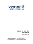
1
HUMIDITY CHAMBER SCO26H SCO26H-2 PREVIOUSLY DESIGNATED 2428H 2428H-2 W ITH MICRO PROCESSOR CONTROL INSTALLATION AND OPERATION INSTRUCTIONS Revised 01/2014 4861693 Sheldon Manufacturing Inc. P.O. Box 627 Cornelius, Oregon 97113 EMAIL: [email protected] INTERNET: http://www.Shellab.com/~Shellab 1-800-322-4897 (503) 640-3000 FAX (503) 640-1366 TABLE OF CONTENTS SECTION 1.0 RECEIVING AND INSPECTION SECTION 2.0 GRAPHIC SYMBOLS SECTION 3.0 INSTALLATION AND FACILITIES REQUIREMENTS SECTION 4.0 CONTROL OVERVIEW SECTION 5.0 THEORY OF OPERATION SECTION 6.0 OPERATION SECTION 7.0 MAINTENANCE SECTION 8.0 TROUBLESHOOTING SECTION 9.0 PARTS LIST SECTION 10.0 UNIT SPECIFICATIONS SECTION 11.0 HUMIDITY VS CONDENSATION CHART SECTION 12.0 WIRING DIAGRAM SECTION 13.0 PLUMBING DIAGRAM These units are TUV CUE listed as CO2 incubators for professional, industrial, or educational use where the preparation or testing of materials is done at approximately atmospheric pressure and no flammable, volatile, or combustible materials are being heated. These units have been tested to the following requirements: CAN/CSA C22.2 No. 61010-1:2012 CA N/CSA C22.2 No. 61010-2-010 + R:2009 UL 61010-1:2004 + R:2005-07 + R:2008-10 UL 61010A-2-010:2002 UL 61010-1:2012 EN 61010-1:2010 EN 61010-2-010:2003 IEC 61010-1:2010 IEC 61010-2-010:2003 1 Section INTRODUCTION Thank you for choosing a humidity testing incubator. These units are not intended for use at hazardous or household locations. Before you use the unit, read this entire manual carefully to understand how to install, operate, and maintain the unit in a safe manner. Your satisfaction with the unit will be maximized as you read about its safety and operational features. Keep this manual for use by all operators of the unit. Ensure that all operators of the unit are given appropriate training before you put the unit in service. Note: Use the unit only in the way described in this manual. Failure to follow the guidelines and instructions in this manual may be dangerous and illegal. General Safety Considerations Your incubator and its recommended accessories have been designed and tested to meet strict safety requirements. For continued safe operation of your incubator, always follow basic safety precautions including: Read this entire manual before using the incubator. Be sure you follow any city, county, or other ordinances in your area regarding the use of this unit. Use only approved accessories. Do not modify system components. Any alterations or modifications to your incubator may be dangerous and will void your warranty. Always plug the unit’s power cord into a grounded electrical outlet that conforms to national and local electrical codes. If the unit is not grounded, parts such as knobs and controls may conduct electricity and cause serious injury. Do not connect the unit to a power source of any other voltage or frequency beyond the range stated on the data plate at the rear of the unit. Do not modify the power cord provided with the unit. If the plug does not fit an outlet, have a proper outlet installed by a qualified electrician. Avoid damaging the power cord. Do not bend it excessively, step on it, place heavy objects on it. A damaged cord can easily become a shock or fire hazard. Never use a power cord after it has become damaged. 2 Section RECEIVING AND INSPECTION Your satisfaction and safety require a complete understanding of this unit, including its proper function and operational characteristics. Read the instructions thoroughly and be sure that all operators are given adequate training before attempting to put the unit into service. NOTE: This equipment must be used only for its intended application; any alterations or modifications will void your warranty. 1.1 Inspection: The carrier, when accepting shipment, also accepts the responsibility for safe delivery and is liable for loss or damage claims. On delivery, inspect for visible exterior damage, note and describe on the freight bill any damage found, and enter your claim on the form supplied by the carrier. 1.2 Inspect for concealed loss or damage on the unit itself both interior and exterior. If any, the carrier will arrange for official inspection to substantiate your claim. 1.3 Return Shipment: Save the shipping crate until you're sure all is well. If for any reason you must return the unit, first contact your dealer for authorization and supply nameplate data, including the serial number. For information on where to contact Customer Service please see the manual cover. 1.4 Accessories: Make sure all of the equipment indicated on the packing slip is included with the unit. Carefully check all packaging before discarding. All models are equipped with 6 shelves, 24 shelf clips and 4 leveling feet. 3 Section INSTALLATION Local city, county or other ordinances may govern the use of this equipment. If you have any questions about local requirements, please contact the appropriate local agency. Installation may be performed by the end user. It is unnecessary for this unit to be installed by a technician. Under normal circumstances this unit is intended for use inside, at room temperatures between 5°C and 30°C, at no greater than 75% relative humidity (at 25°C) and with a supply voltage that does not vary by more than 10%. Customer Service should be contacted for operating conditions outside of these limits. 3.1 Power Source: See the unit's serial data plate for voltage, cycle, wattage and ampere requirements. If matched to your power source, plug the power cord into a grounded outlet. VOLTAGE SHOULD NOT VARY MORE THAN 10% FROM THE SERIAL PLATE RATING. These units are intended for 50/60 Hz application. A separate circuit is recommended to preclude loss of product due to overloading or circuit failure. Note that electrical supply to the unit must conform to all local and national electrical codes. 3.2 Location: In selecting a site, consider all conditions which may affect performance, such as extreme heat from steam radiators, stoves, ovens, autoclaves, etc. Avoid direct sun, fast moving air currents, heating/cooling ducts and high-traffic areas. To ensure air circulation around the unit, allow a minimum of 5cm between the unit and any walls or partitions which might obstruct free air flow. Caution: Position and level the apparatus before connecting to water supply. 3.3 Lifting and Handling: These units are heavy and care should be taken to use appropriate lifting devices that are sufficiently rated for these loads. Units should only be lifted from their bottom surfaces. Doors, handles and knobs are not adequate for lifting or stabilization. The unit should be completely restrained from tipping during lifting or transport. All moving parts, such as shelves and trays should be removed and doors need to be positively locked in the closed position during transfer to prevent shifting and damage. 3.4 Leveling: The unit must sit level and solidly. Leveling feet (supplied) are to be installed at the holes in the base of the unit. Turn them counterclockwise to raise level. If the unit must be moved, turn the leveling feet in all the way to prevent damage. 3.5 Cleaning: The incubator was cleaned at the factory, but not sterilized. It should be disinfected prior to use. Remove all interior parts including shelves and shelf assembles. Clean the chamber with a disinfectant that is appropriate to your application. Similar periodic cleaning is strongly recommended. DO NOT USE chlorine-based bleaches or abrasives as this will damage the stainless steel interior. DO NOT USE spray cleaners that might leak through openings and cracks and get on electrical parts or that may contain solvents that will harm the coatings. A similar periodic cleaning is recommended. WARNING: Never clean the unit with alcohol or flammable cleaners with the unit connected to the electrical supply. Always disconnect the unit form the electrical service when cleaning and assure all volatile or flammable cleaners are evaporated and dry before reattaching the unit to the power supply. 3.6 Humidification Water Supply: On the back of the body there is a 1/4" compression fitting marked WATER IN. This fitting should only be plumbed to a DISTILLED WATER supply source. Please note that when attaching the water supply line to the fitting on the unit, two wrenches must be used: one to hold the fitting from turning in the panel, while using the other to tighten the compression fitting. The supply source should be gravity fed or pressure can be regulated to no more than 2 psi with a water pressure regulator valve. Deionized or tap water should NOT be used. They will have a detrimental effect on the unit causing corrosion or obstructions and premature failure of this assembly, and VOID your warranty. 3.7 Fill the Vapor Generator: It takes approximately 880cc (0.88 Liter) to initially fill the vapor generator, after that a continuous supply is required to maintain the operating level. If the supply is disconnected or in some other manner cut off from the vapor generator, the level will drop and the float switch in the vapor generator will shut the vapor generator off and the low water indicator light on the front panel will be lit. 3.8 Water Drain Line: On the external back of the test chamber, at the bottom, there is a copper drain line for excess condensation to drain from the bottom of the chamber. Ideally, this line would be run into a floor drain, but could be run to a shallow pan with an automatic sump pump. Under no circumstances should this line be plugged. If the line is plugged the condensation will pool on the floor of the test chamber and flow out when the door is opened. 3.9 Vapor Trap: Located in the water drain line, this trap consists of a solenoid valve controlled by a timer. The timer is set to open and allow condensate to be removed from the unit on a regular basis. This will prevent the chamber humidity and CO2 from escaping and still allow any condensation to drain away. 3.10 Pressure Relief Valve: Marked RELIEF, this valve is located just to the right of the WATER IN fitting at the back of the unit. It provides pressure relief for the vapor generator system. The cracking pressure is 5. psi. The protective shipping cap must be removed before operation as this valve should never be plugged or covered. 4 Section GRAPHIC SYMBOLS Your incubator has been provided with a display of graphic symbols which is designed to help in identifying the use and function of the available user adjustable components. Symbol Identification Indicates that you should consult your operator’s manual for further instructions. Indique que l'opérateur doit consulter le manuel d'utilisation pour y trouver les instructions complémentaires. Indicates “Temperature” Repère "température" C Indicates "Degrees Centigrade" Repère "Degrés Centigrades" Indicates "Relative Humidity" RH Repère "Humidité Relative" Indicates “Over Temperature Protection” Signale un "dépassement de température" Indicates “AC Power” Repère "secteur AC" I O Indicates the power is “ON” Repère de la position "MARCHE" de l'interrupteur d'alimentation Indicates the power is “OFF” Repère de la position "ARRÊT" de l'interrupteur d'alimentation Indicates “Protective Earthground” Repère de la "terre de protection" Indicates “Manually Adjustable” Signale un élément "réglable manuellement" Indicates “Potential Shock Hazard” behind partition Signale un "risque potentiel d'électrocution" au-delà de la cloison. Indicates “Unit should be recycled” (Not disposed of in land-fill) Indique “l’appareil doit être recyclé“ (Ne pas jeter dans une décharge) 3 5 Section CONTROL OVERVIEW 4.1 4.2 4.3 4.4 4.5 4.6 4.7 4.8 Power Switch: The main power I/O (On/Off) switch controls all power to the unit, and must be in the I/On position before any systems are operational. Over Temperature Limit: This control is marked “Set Over Temp” and is adjacent to the power switch. It is completely independent of the Main Temperature Controller and guards against any failure which would allow the temperature to drastically rise past set point. If the temperature rises to the Set Over Temp Limit set point, the Limit takes control of the heating element and allows temporary use of the unit until the problem can be resolved or service can be arranged. Please note that it is not recommended that the unit be allowed to operate using only the Over Temp Limit thermostat as temperature uniformity will suffer. Over Temp Indicator Light: This pilot light, located on the Main Control Panel just above the word “Over Temp Activated”, comes ON when the Over Temperature Limit thermostat is activated. Under normal operating conditions this pilot light should not be lit. Main Temperature Controller: This control is marked “Set Temperature C” and indicates the internal incubator temperature in 0.10C increments. The UP/DOWN buttons are used to input the set point, calibrating the display, and muting or unmuting the audible alarm. The HIGH and LOW alarm indicators will light whenever there is an alarm condition associated with the internal incubator temperature.. The MUTE indicator will light whenever the audible alarm has been deactivated. Heating Indicator Light: This pilot light is marked “Heating Activated” and is on when the heating elements have been activated to reach and maintain the desired set point. CO2 Controller: This controller is labeled “SET CO2 %” and indicates the percentage of CO2 content within the chamber to 0.1%. The UP/DOWN buttons are used to input the set point, calibrating the display, and muting or unmuting the audible alarm. The HIGH and LOW alarm indicators will light whenever there is an alarm condition associated with the CO2% within the chamber. The MUTE indicator will light whenever the audible alarm has been deactivated. CO2 Indicator Light: This pilot light is labeled “CO2 Injecting” and is on whenever the Carbon Dioxide control has been activated and is actively injecting CO2 gas via the solenoid valve. Relative Humidity Controller: This control is marked “Set Humidity Level”, and consists of the analog scale knob for setting the RH set. The Relative Humidity Controller maintains internal humidity through a proportional solid state control. The controller utilizes a solid state thin film capacitive humidity sensor to sense the humidity within the chamber. 4.9 Humidity Injection Indicator: This pilot light is marked “HUMIDITY INJECTING” and is on when water vapor is being injected into the chamber from the vapor generator. 4.10 Water Low Indicator Light: This pilot light is marked “WATER LOW” and is on when the water level drops in the vapor generator. The float switch is tripped, the vapor generator is turned off, and water is released from the supply. When the vapor generator becomes full, the float switch is tripped again, the vapor generator is turned on, and the pilot light turns off. Intermittent flashing of this light is expected under normal operating conditions. 6 Section THEORY OF OPERATION These humidity chambers are designed to maintain temperature and relative humidity at set points controllable by the operator at the front panel. Air is constantly being circulated through the chamber, monitored for comparison to set points and controlled as necessary. On all units, heating is done by electric resistance heaters that turn off and on for temperature control Chamber humidification is achieved by means of a low-pressure vapor generator that injects water vapor into the chamber through a small orifice. The water vapor is introduced into the chamber at the blower discharge. It should be noted that the unit has no way of achieving humidity lower than that the level present in the ambient environment. 7 Section OPERATION It is recommended that your unit be allowed to reach operating temperature before engaging the humidifying system. This requires setting the RH set point to the farthest counterclockwise position until the unit is at operating temperature. See Section 6.6 for changing the RH set point. 7.1 Turn the power switch to the I/ON position. Turn the Over Temp Limit thermostat to its maximum position, clockwise and place the shelves in the chamber. 7.2 Place a reference thermometer in the chamber where it can be easily viewed, and so that it is not touching any shelves or chamber walls. Taping the thermometer to a petri dish is a method that works well. 7.3 Set Main Temperature Control: To enter the set point on the control, push and release either the UP or DOWN arrow pad one time and the digital display will start to blink from bright to dim. While blinking, the display is showing the set point, which can be changed to the desired temperature by pushing the UP or DOWN arrow pads. If the arrow pads are not pushed within five (5) seconds, the display will stop blinking and will read the temperature in the chamber. Allow at least twenty- four (24) hours for the temperature to stabilize. It is recommended that set point adjustments are made again after the calibration procedure is completed. 7.4 Calibrating Temperature Control: Compare the reading on the reference thermometer with the digital display. If there is an unacceptable difference, put the display into calibrate mode by pressing both the UP and DOWN arrow pads at the same time and holding them in until the two outside decimal points start to flash (approximately 5 seconds). When the decimal points are flashing, the display can be calibrated to match the reference thermometer by pressing the UP or DOWN arrow pad until the display reads the correct reference value. Allow the unit to stabilize again overnight before re-calibrating. 7.5 Set the Over Temp Limit Thermostat: After the Main Temperature Control is set and calibrated the Over Temp Limit needs to be set. First turn the control knob counterclockwise just until the Safety Indicator light comes on. Then very slowly turn the knob clockwise just until the Over Temp Indicator light goes off. The Limit thermostat should now be set approximately 1.0 degree above the Main Temperature Control set point. 7.6 Set Humidity Control: First, place a reference hygrometer in the chamber where it can be easily viewed. To adjust the internal humidity level turn the humidity control knob clockwise from LOW to HIGH until the desired setpoint is reached. The low value on the scale is approximately 40% RH. The high value on the scale is dependent on the internal temperature setpoint. See Section 11 for a graph of the achievable humidity values with reference to internal temperature setpoint and the dewpoint. Allow at least twenty four (24) hours for the unit to stabilize. 7 8 Section MAINTENANCE Warning: Prior to any maintenance or service on this unit, disconnect the power cord from the power source. Before reattaching the unit to its power source, be sure all volatile and flammable cleaners are evaporated and dry. Avertissement: Avant d'effectuer toute maintenance ou entretien de cet appareil, débrancher le cordon secteur de la source d'alimentation. Avant de reconnecter l'appareil sur le secteur, s'assurer que tous les produits de nettoyage volatiles et inflammables sont complètement évaporés. The design of the chamber is such that periodic maintenance is kept to a minimum. No lubrication or adjustments of components is needed. Note: The unit chamber should be cleaned and disinfected prior to use. 8.1 Cleaning: Periodic cleaning is required. To clean the incubator, perform the following steps: 8.1.1. Remove all of the interior parts, if assembled. 8.1.2. Clean the incubator with a mild soap and water solution, including all corners. DO NOT USE spray cleaners that might leak through openings and cracks and get on electrical components, or that may contain solvents that will harm coatings. DO NOT USE chlorine-based bleaches or abrasives, as they will damage the painted interior. Rinse with distilled water and wipe dry with a soft cloth. Special care should be taken when cleaning around the sensing heads to prevent damage. 8.1.3. 8.1.4. 8.2 Disinfecting: Disinfect the incubator on a regular basis. To disinfect the incubator, perform the following steps. 8.2.1. Remove all of the interior parts, if assembled. 8.2.2. Disinfect the incubator, including all corners, using a suitable disinfectant. Shelves and shelf clips are autoclaveable. DO NOT USE spray disinfectants that might leak through openings and cracks and get on electrical components, or that may contain solvents, corrosives, or abrasives that will harm the painted coatings. Special care should be taken when cleaning around sensing heads to prevent damage and around the door gasket so as not to impair the positive seal. 8.2.3. If a hazardous material/substance has been damaged in the unit, immediately initiate your site’s Hazardous Material Spill Containment protocol. Contact your local Site Safety Officer and follow instructions per the policy and procedures established for your site. 8.2.4. There are many commercially available disinfectants available that are non-corrosive and nonabrasive and suitable for use on painted surfaces. Contact your local Site Safety Officer for detailed information for the proper disinfectants suitable for your operation. Warning: Never clean the unit with alcohol or flammable cleaners and assure all volatile or flammable cleaners are evaporated and dry before reattaching the unit to the power supply. Avertissement: Ne jamais nettoyer l'appareil à l'alcool ou avec des nettoyants inflammables et veiller à ce que les produits volatils ou inflammables soient entièrement évaporés avant de rebrancher le content d'alimentation de l'appareil. Periodically inspect the door latch, trim, catch and gasket for signs of deterioration. Failure to maintain the integrity of the door system will shorten the life span of the incubator. 9 Section TROUBLESHOOTING and SERVICE Always make a visual inspection of the unit and control console when troubleshooting. Look for loose or disconnected wires which may be the source of the trouble. The incubator is designed so that no internal electrical servicing should be required under normal conditions. If electrical servicing is necessary, it should be performed by qualified service personnel. For information on where to reach technical service please see the manual cover. FOR PERSONAL SAFETY, ALWAYS DISCONNECT THE POWER BEFORE SERVICING. TEMPERATURE Temperature too high – display and actual match 1/ controller set too high-see see section 6.3 2/ controller failed on – call Customer Service 3/ wiring error – call Customer Service 4/ Peltier condensate collector failure DISPLAY reads "HI" or "400"+ probe is unplugged, is broken or wire to sensor is broken – trace wire from display to probe; move wire and watch display to see intermittent problems Chamber temp goes way over set point and then settles to set point Recalibrate – see section 6.4 Temperature too low – display and actual match 1/ high limit set too low – see section 6.5 2/ controller set too low – see section 6.3 3/ unit not recovered from door opening – wait for display to stop changing 4/ unit not recovered from power failure or being turned off – incubators will need 24 hours to warm up and stabilize 5/ element failure – see if heating light is on; compare current draw to data plate 6/ controller failure – confirm with front panel lights that controller is calling for heat 7/ high limit failure – confirm with front panel lights that Over Temp Limit is operating correctly 8/ wiring problem – check all functions and compare wiring to users manual especially around any areas recently worked on 9/ loose connection – check shadow box for loose connections Display reads "LO" 1/ sensor is plugged in backwards – reverse sensor wires to controller 2/ if ambient temperature is lower than range of unit – compare set points and ambient temperature to rated specifications in users manual Unit will not heat over some temperature that is below set point 1/ confirm that fan is moving and that amperage and voltage match data plate – check fan motor motion in shadow box and feel for air movement in chamber 2/ confirm that set point is set high enough –turn Over Temp Limit Thermostat all the way clockwise and see if heating light or safety light comes on 3/ check connections to sensor 4/ check calibration – using independent thermometer, follow instructions in section 6.4 Unit will not heat up at all 1/ verify that controller is asking for heat by looking for Heating light – if pilot light is not on continuously, there is a problem with the controller 2/ check amperage – amperage should be virtually at maximum rated (data plate) amperage 3/ do all controller functions work? 4/ is the Over Temp Limit Thermostat set high enough? – for diagnostics, should be turned fully CCW with the pilot light never on 5/ has the fuse/circuit breaker blown? Indicated chamber temperature unstable 1/ ±0.1 may be normal 2/ is fan working? – remove top panel and verify movement of cooling fan in center of shadow box 3/ is ambient radically changing – either door opening or room airflow from heaters or air conditioning? – stabilize ambient conditions 4/ sensor miss-located, damaged or wires may be damaged - check mounts for control and Over Temp Limit Thermostat sensors, then trace wires or tubing between sensors and controls 5/ calibration sensitivity – call Customer Service 6/ high limit set too low – be sure that Safety is more than 5 degrees over desired set point; check if Over Temp Limit pilot light is on continuously; turn controller knob completely clock-wise to see if problem solved then follow instructions in section 6.4 7/ electrical noise – remove nearby sources of RFI including motors, arcing relays or radio transmitters 8/ bad connection on temperature sensor or faulty sensor – check connectors for continuity and mechanical soundness while watching display for erratic behavior; check sensor and wiring for mechanical damage 9/ bad connections or faulty solid state relay – check connectors for mechanical soundness and look for corrosion around terminals or signs of arcing or other visible deterioration 10/ Water jacket empty or low – check indicator warning light or water level at fill port in back of unit. 11/ Peltier condensate collector failure Will not maintain set point 1/ assure that set point is at least 5 degrees over ambient 2/ see if ambient is fluctuating Display and actual (from reference thermometer) don’t match 1/ calibration error – see operator’s manual 2/ temperature sensor failure – evaluate if pilot light is operating correctly 3/ controller failure – evaluate if pilot light is operating correctly 4/ allow at least two hours to stabilize 5/ see if reference thermometer is certified Reference thermometer does not match digital display See Temp Calibration in Section 10 Can't adjust set points or calibration 1/ turn entire unit off and on to reset 2/ if repeatedly happens, call Customer Service Calibrated at one temperature, but not at another This can be a normal condition when operating temperature varies widely, e.g., >30C° difference between setpoints. For maximum accuracy, calibration should be done at close to the set point temperature. HUMIDITY LEVEL Can't achieve rated humidity/temp 1/ relative humidity sensor or controller failure 2/ check for bad door seal 3/ check for leaking water around steamer 4/ confirm a sufficient and distilled water source 5/ calibrate humidity sensor with independent reference 6/ assure that pressure relief valve is closed 7/ assure that steamer is working (see Humidity Section-4) Can't adjust set points or calibration 1/ confirm all wire connections 2/ confirm software revision 3/ call Customer Service Steam generator not working 1/ check if fill solenoid, injection valve, relief valve, float switch and relays are working – see schematic in manual 2/ check for water leaks around steamer 3/ verify that relays are working 4/ verify that float switch is working 5/ confirm that heater is working a- power to coil b- is unit burned/shorted out 6/ pressure switch is working 7/ plumbing leak Humidity unstable 1/ circulating fan failure a- motor failure or no voltage to motor b- fan not turning c- ducts blocked 2/ relative humidity is lower than the unit can achieve at that operating temperature 3/ chamber leaks a- motor shaft seals b- door seal c- air intake flapper MECHANICAL Door not sealing 1/ adjust hinge blocks or twist the door. 2/ Confirm that unit has not been damaged and body is not square. Motor doesn't move 1/ if shaft spins freely: check connections to motor and check voltage to motor; 2/ if shaft rubs or is frozen, relieve binding and retest Motor makes noise 1) Make sure that the fan or blower wheel is not contacting its housing. Adjust the motor mounting bracket position to re-center the fan or blower wheel, if necessary. 2) Check the fan or blower wheel for damage or out of balance condition. Replace the fan or blower wheel if it is damaged or out of balance. 3) Turn the motor shaft to make sure that it spins freely. If it binds or the bearings make a rubbing or scrapping sound then replace the motor. Water leaking 1/ If leaking inside: dry chamber, run at temperature with door open. Check all seams with flashlight including front face. 2/ If leaking outside: dry out and see if leak repeats and find source of leak. Sources may include: fittings that need tightening, condensation due to missing insulation or a leak developed in humidity generator. OTHER Controller on at all times - "locked-up" 1/ Adjust set point to room temperature. If the light goes out but is still heating, replace the solid state relay. 2/ turn unit off and on to reset 3/ if cannot change any condition on the front panel, call Customer Service Front panel displays are all off 1/ Check for wire damage. Unit or wall fuse/circuit breaker is blown 1/ check wall power source 2/ compare current draw and compare to specs on data plate 3/ see what other loads are on the wall circuit Unit will not turn on 1/ check wall power source 2/ check fuse/circuit breaker on unit or in wall 3/ see if unit is on, e.g., fan or heater, and just controller is off 4/ check all wiring connections, esp. around the on/off switch Condensate appears on interior chamber walls 1/ Some condensation may be normal 2/ Minimize the movement of air around the unit and reduce the number of door openings 3/ Turn the humidity control counterclockwise until the condensation level is acceptable Condensate appears on interior glass door surface 1/ Some condensation may be normal 2/ Minimize the movement of air around the unit and reduce the number of door openings 3/ Turn the humidity control counterclockwise until the condensation level is acceptable Contamination in chamber 1/ see cleaning procedure in operator’s manual 2/ develop and follow SOP for specific application; include definition of cleaning technique and maintenance schedule Service If none of the suggestions listed above in the Troubleshooting guide have solved the problem Customer Service should be contacted for assistance. Call 1-800-322-4897, and have the model number, serial number and voltage (listed on the date plate on the side of the incubator) as your service representative will require it. 10 Section PARTS LIST SCO26H (2428H) SCO26H-2 (2428H-2) 115V 220V Adjustable Feet 2700500 2700500 Blower Wheel, Aluminum 2600535 2600535 Blower Wheel, Plastic 2600544 2600544 Circuit Breaker 1100500 1100500 Element 2350563 2350554 Fan Blade 2600551 2600551 Fan Motor 4880564 4880563 Float Switch 7850563 7850563 Humidity Control 1750553 17560554 Humidity Sensor 4100504 4100504 Motor U.E.C. 4880512 4880512 ON/OFF Switch 7850570 7850570 Pilot Light, Green 4650554 4650554 Pilot Light, Red 4650553 4650553 Power Cord 1800516 1800537 Power Cord - European NA 1800541 Power Exhaust Assembly 9990559 9990562 Pressure Relief Valve 8600567 8600567 Pressure Switch 7850574 7850574 Relay 7030536 7030528 Shelf 5120525 5120525 Shelf Clip (4/Shelf) 1250512 1250512 Solenoid Valve 8600576 8600578 Temperature Controller 1750549 1750550 Thermostat, High Limit 1750861 1750861 Vapor Generator Assembly 9990663 9990664 Vapor Generator Element 2350520 2350521 DESCRIPTION 11 Section UNIT SPECIFICATIONS Weight Shipping Net All Models 480 lbs. 341 lbs. Dimensions Exterior WxDxH (in.) Interior WxDxH (in.) All Models 44 x 32.75 x 57 Capacity Cubic Feet All Models 28.5 Temperature All Models 28 x 20.25 x 26 Range Humidity 15 to 50 40-95% 12 Section RELATIVE HUMIDITY CHART 13 Section WIRING DIAGRAM SCO26H (2428H) (9851429) FUSED INLET 4200505 EMI FILTER 2800503 BLACK WHITE WHITE BLACK GREEN CHERRY ROUND POWER SWITCH 7850532 POWER ON LIGHT 4650554 P1 P7 WHITE 14 BLACK P3 DOOR SWITCH 7850578 OTL RED 1750862 BLACK BLACK TEMPERATURE DISPLAY 1750726 4-20MA BOARD CO2 & TEMP 1750667 RECORDER JACKS 6900522 RED 18G RED 18G 4-20MA BOARD RH 1750945 BLACK 18G RED 18G BLACK 18G OTL LIGHT 4650553 4 1 P9 P10 2 BLACK 18G 10 WHITE P8 HEAT LIGHT 5 9 RED P5 WHITE RELAY 7030530 ORANGE P4 13 BL HT P2 BLACK 4650554 WH HT 6 HEATER 2350563 P13 HIGH (NEUT) J2 4 LOOP CONTROL BOARD SL# 1750978 HIGH LOW YELLOW CO2 SOLENOID 8600528 LOAD 1 J4 J17 CO2 SENSOR P16 LOAD 3 J6 WHITE P19 BROWN LOAD 4 J7 ALARM CONTACTS RH LIGHT 4650554 WHITE P20 RED 22G BROWN BLACK 22G BLACK 22G RED 22G P24 RH SENSOR 4100504 RH SOLENOID 8600576 WATER LOW LIGHT 4650553 P21 WHITE 9 BLACK 5 P21 PRESSURE SWITCH 7850574 RED 1 13 GREY 1 STEAMER HEATER 2350532 RED HT 2 FLOAT SWITCH 7850563 P3 WHITE 18G P4 WH HT P5 WHITE P7 WATER FILL SOLENOID 8600576 14 BLACK TB 8 RED HIGH LIMIT 220°C 9990691 GREY BLACK 4 WHITE WHITE P8 BLACK FG ACN ACL POWER SUPPLY 24VDC 6750517 NC BLACK HF+ HFCF+ RED CF- PELTIER 7010547 WHITE WHITE P9 P6 P12 TEC+ TECTEC+ TEC- DRAIN TIMER 8250517 BLACK 18G 7 WHITE P10 WHITE 18G P11 6 8 1 4 2 3 5 BLUE 18G DRAIN SOLENOID 8600568 TB5-6 STEAMER RELAY 7030536 P23 P1 P2 P20 P22 P17 WHITE BLACK 12VDC POWER SUPPLY 6750507 P12 P18 GLASS HEATER WHITE S SG GND IR CO2 SENSOR 8320510 P15 YELLOW IN OUT P6 P14 WHITE RED LOAD 2 J5 DOOR SENSOR J16 BLACK 22G MAIN TEMP SENSOR HUMIDITY SENSOR BROWN 22G WHITE 22G RH DIAL 1750979 WHITE 22G J9 J8 CO2 DISPLAY 1750727 BLACK 18G CO2 LIGHT 4650554 8 12 WHITE RED WHITE YELLOW (HOT) J1 MUTE P19 7 BLACK ORANGE TB1 BUSS EARTH GRD J3 WHITE J10 COMMUNICATION BLUE BM ORANGE 11 LOW TB2-4 MUTE WIRING DIAGRAM SCO26H-2 (2428H-2) (9851430) FUSED INLET 4200505 EMI Filter 2800503 BLACK WHITE WHITE BLACK GREEN CHERRY ROUND POWER SWITCH 7850532 POWER ON LIGHT 4650554 P1 P7 BLACK WHITE 14 BLACK P3 BLACK RED BLACK TEMPERATURE DISPLAY 1750726 4-20MA BOARD CO2 & TEMP 1750667 RECORDER JACKS 6900522 RED 18G RED 18G 4-20MA BOARD RH 1750945 BLACK 18G RED 18G BLACK 18G 4 WHITE BLACK 18G 10 1 2 ½ OTL 1750813 6 P8 P9 4 HEAT LIGHT 5 9 RED P5 OTL LIGHT 4650553 RELAY 7030531 ORANGE P4 WHITE 2 WH HT DOOR SWITCH 7850578 13 BL HT P2 4650554 HEATER 2350563 1 ½ OTL 1750813 P10 P13 HIGH 4880504 ORANGE J10 (NEUT) J2 4 LOOP CONTROL BOARD SL# 1750978 HIGH LOW J8 MAIN TEMP SENSOR CO2 SOLENOID 8600529 J17 CO2 SENSOR J16 HUMIDITY SENSOR YELLOW WHITE P19 BROWN LOAD 4 J7 ALARM CONTACTS RH LIGHT 4650554 WHITE P20 RED 22G RH SENSOR 4100504 P24 BROWN RH SOLENOID 8600578 WATER LOW LIGHT 4650553 P21 WHITE 5 BLACK 3 P21 PRESSURE SWITCH 7850574 RED 1 7 GREY 1 STEAMER HEATER 2350533 RED HT 2 FLOAT SWITCH 7850563 P3 WHITE 18G P4 WH HT P5 WHITE P7 WATER FILL SOLENOID 8600578 8 BLACK TB 8 RED HIGH LIMIT 220°C 9990691 GREY BLACK 4 WHITE WHITE P8 BLACK FG ACN ACL NC POWER SUPPLLY 24VDC 6750517 BLACK HF+ HFCF+ RED CF- PELTIER 7010547 WHITE WHITE P9 P6 P12 TEC+ TECTEC+ TEC- DRAIN TIMER 8250517 BLACK 18G 7 6 8 1 5 4 2 3 BLUE 18G DRAIN SOLENOID 8600569 WHITE P10 WHITE 18G P11 TB5-6 STEAMER RELAY 7030528 P23 P1 P2 P20 P22 P17 WHITE BLACK 12VDC POWER SUPPLY 6750507 P12 P16 LOAD 3 J6 BLACK 22G RED 22G P6 BLACK 22G IR CO2 SENSOR 8320510 P15 P18 GLASS HEATER WHITE S SG GND BROWN 22G WHITE 22G BLACK 22G WHITE 22G J9 DOOR SENSOR P14 WHITE RED LOAD 2 J5 IN OUT BLACK 18G YELLOW LOAD 1 J4 RH DIAL 1750979 P19 CO2 LIGHT 4650554 8 12 WHITE BLACK RED WHITE YELLOW (HOT) J1 MUTE CO2 DISPLAY 1750727 BM BLUE ORANGE TB1 BUSS EARTH GRD J3 COMMUNICATION 7 WHITE 11 LOW TB2-4 MUTE 14 Section PLUMBING DIAGRAM