1
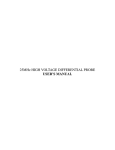
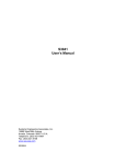
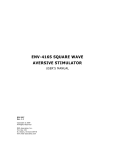
100MHz DIFFERENTIAL PROBE
USER'S MANUAL (SI-9101)
This probe is in compliance with IEC-61010-031 CAT III, Pollution
Degree 2.
1. Safety Terms and Symbols
Terms appear in this manual:
WARNING. Warning statements identify conditions or
practice that could result in injury or loss life.
CAUTION. Caution statements identify conditions or
practice that could result in damage to this product or
other property.
Symbols appear on the product:
Danger
High Voltage
Protective
(Earth) Terminal
Attention
Refer to Manual
2. General Safety Summary
Review the following safety precautions to avoid injury and prevent
damage to this probe or any products connected to it.
Observe Maximum Working Voltage
To avoid any injury, do not use the probe under the condition that
the voltage between either input lead or earth is above 1000Vrms
CAT III or above 1000 Vrms CAT III between the two leads. This
voltage rating applies to both 1/10 & 1/100 settings.
Must be Grounded
This probe is grounded with the shell of BNC connector and an
auxiliary grounding terminal, through the grounding conductor of the
power cord of the measurement instrument.
Before making connections to the input leads of this probe, ensure
that the output BNC connector is attached to the BNC connector of
the measurement instrument and the auxiliary grounding terminal is
connected to a proper ground, while the measurement instrument is
properly grounded.
Use Fused Test Prods if Necessary
If this probe is intended to use for measurements in circuits of
INSTALLATION CATEGORY III, it should incorporate with fused
test prods.
Do Not Operate Without Covers
To avoid electric shock or fire hazard, do not operate this probe
with covers removed.
Do Not Operate in Wet/Damp Conditions
To avoid electric shock, do not operate this probe in wet of damp
conditions.
Do Not Operate in Explosive Atmosphere
To avoid injury or fire hazard, do not operate this probe in an
explosive atmosphere.
Avoid Exposed circuitry
To avoid injury, remove jewelry such as rings, watches, and other
metallic objects. Do not touch exposed connections and
components when power is present.
Use Proper Power Source
To ensure this probe function well, use four AA cells or
6VDC/200mA or regulated 9VDC/120mA mains adaptor or power
lead. Do not operate this probe from a power source that applies
more than the voltage specified.
Do Not Operated With Suspected Failures
If you suspect there is damage to this probe, have it inspected by
qualified service personnel.
3. Description
By enabling conventional oscilloscopes to display and measure incircuit waveforms that are referenced to high common mode voltages.
The differential probe extends the measurement capability of
oscilloscopes in electronic power converters, inverters, motor speed
controls, switch mode power supplies and many applications.
4. Installation
a. Simply plug-in the output BNC connector of this probe to the
vertical input of a general purposed oscilloscope or other
measurement instrument, and connects the auxiliary grounding
terminal to a proper ground. The measurement instrument must have
a ground referenced.
b. Connect an appropriate power source to this probe and then turn
it on.
c. Select the proper attenuation ration, when measuring signals
below 70V; switch the attenuation to 1/10 in order to get higher
resolution and less noise. Otherwise, set the attenuation ratio to 1/100
when measuring signals up to 700V.
WARNING. To protect against electric shock, use only
the accessory supplied with this differential probe.
d. Using the appropriate probe accessories, connect the inputs to the
circuits under measurement.
CAUTION. This probe is to carry out differential
measurement between two points on the circuit under
measurement. This probe is not for electrically
insulating the circuit under measurement and the
measuring instrument.
5. Appearance
The differential probe looks as follows.
a. Output Cable The output BNC connector and the auxiliary grounding
terminal are connected to the oscilloscope.
b. Input Leads
The input leads of the differential probe are connected to
sprung hooks that come with the probe.
c. Sprung Hooks The sprung hooks are connected safety to test points in
circuits. Under measurement.
6. Power Leads
We offer two types power leads;
a. Adaptor-Lemo® Lead: For the oscilloscope whose power connector
is Lemo® connector.
b. Adaptor-Probus® Lead: For the oscilloscope whose power connector
is Probus® connector.
c. USB Power Cord: For the oscilloscope which offers USB connector.
7. Specifications
Bandwidth
Attenuation Ratio
Accuracy
Input Impedance
Input Voltage
- Category
DC to 100MHz (-3dB)
1:10/100
+/-2%
4Mohm//7pF each side to ground
CAT III
+/-70V (DC + Peak AC) or 70Vrms @1/10
- Differential Range*
+/-700V (DC + Peak AC) or 700Vrms @1/100
- Common Mode
+/-700V (DC + Peak AC) or 500Vrms @1/10 &
Range*
1/100
- Absolute Max.
Voltage*
+/-1000V(DC + Peak AC)or 1000Vrms @ 1/10
(Differential or
& 1/100
Common Mode)
Output Voltage
- Swing (into
+/-7V
50kohm load)
- Offset (typical)
<+/-5mV
- Noise (typical)
0.9mVrms
- Source Impedance 50ohm (for using 1Mohm imput system
(typical)
oscilloscope)
CMRR (typical)
-85dB@50Hz; -55dB@1MHz
Ambient Operating
-10 to 40 degree centigrade
Temperature
Ambient Storage
-30 to 70 degree centigrade
Temperature
Ambient Operating
25 to 85% RH
Humidity
Ambient Storage
25 to 85% RH
Humidity
Power Requirements
4 x AA cells or 6VDC/200mA mains adaptor**
- Standard
or regulated 9VDC/120mA mains adaptor**
- Options
Power leads
Length of BNC Cable 90cm
Length of BNC Lead 30cm
Weight
500gms
Dimension (LxWxH) 202mm x 83mm x 38mm
* Voltage limit is the lesser of the DC+Peak AC and RMS values.
* a. The supplied voltage must be less than 12V and greater than
4.4V, otherwise the probe could be damaged or can not be operated
properly.
b. Polarity is "+" inside and "-" outside. For wrong polarity, the probe
is protected by built-in circuit, no danger or damage will occur.
c. When the voltage of the cells become too low, the power indicator
on the panel will flicker.
8. Derating Curve/font>
The derating curve of the absolute maximum input voltage in common
mode is shown as follows;
9. Overrange Indicator
The overrange indicator lights red if the voltage of the input signal
exceeds the linear operating range of the probe. When this happens,
the signal on the probe output does not accurately represent the
signal on the probe input.
10. Inspection Procedure
a. Connect the BNC output connector to the vertical input of a
general purposed oscilloscope.
b. Install four AA cells or connect an appropriate mains adaptor or
power lead to the correct line voltage.
c. Set the oscilloscope input to DC coupling and 1V/div. Center the
trace on the display.
d. Connect the input leads of the probe to power lines. e. Set the
range of the probe to 1/10.
f. Then, a 60Hz/50Hz sine-wave of proper amplitude will be
displayed on the screen of the oscilloscope and this means the probe
is working properly.
11. Cleaning
Use a soft cloth to clean the dirt. Prevent damage to probe.
a. Avoid immersing the probe.
b. Avoid using abrasive cleaners.
c. Avoid using chemicals contains benzene or similar solvents.