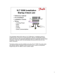
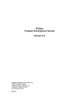
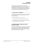
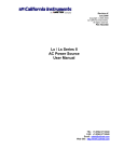
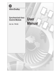
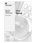
1
S3041
User’s Manual
Systems Engineering Associates, Inc.
14989 West 69th Avenue
Arvada, Colorado 80007 U.S.A.
Telephone: (303) 421-0484
Fax: (303) 421-8108
www.sea-seg.com
02/2004
S3041
User’s Manual
Copyright © 1992 Systems Engineering Associates, Inc.
All Rights Reserved!
WARNING
To ensure the equipment described by this User Manual, as well as the equipment connected to
and used with it, operates satisfactorily and safely, all applicable local and national codes that
apply to installing and operating the equipment must be followed. This includes the National
Electric Code in the USA and other applicable legislation, regulations, and codes in practice
elsewhere. Since codes can vary geographically and can change with time, it is the user’s
responsibility to determine which standards and codes apply, and to comply with them.
FAILURE TO COMPLY WITH APPLICABLE CODES AND STANDARDS CAN RESULT IN
DAMAGE TO EQUIPMENT AND/OR SERIOUS INJURY TO PERSONNEL.
Persons supervising and performing installation or maintenance must be suitably qualified and
competent in these duties, and should carefully study this User Manual and any other manuals
referred to by it prior to installation and/or operation of the equipment.
_____________________________________________________________________________
_
The contents of the User Manual are believed to be correct at the time of printing; however, no
responsibility is assumed for inaccuracies. In the interests of a commitment to a policy of
continuous development and improvement, the manufacturer reserves the right to change the
specification of the product or it’s performance or the contents of the User Manual without notice.
_____________________________________________________________________________
_
Copyright © 1992 Systems Engineering Associates, Inc.
All Rights Reserved !
CONTENTS
1. General Description
1.1
1.2
1.3
1.4
1.5
1.6
1
Resolver Interface
Timing Channels
RPM/Position Display
Brake Wear Compensation
Motion (speed) Signal
Programming
1
1
1
2
2
3
2. Programming
5
2.1
Introduction to PLSdev
2.1.1 Features of PLSdev
2.1.2 System Requirements
2.1.3 Installing PLSdev
2.1.4 Executing PLSdev
5
5
6
6
6
2.2
Menus
2.2.1 Main Development Menu
2.2.2 Channel Edit Menu
7
7
12
2.3
PLS Configuration
2.3.1 Number of PLS Channels
2.3.2 Scale Factor
2.3.3 Remote Display Strobe Time
2.3.4 CH00 Brake Wear Compensation
2.3.5 CH17 Speed Window
15
15
15
15
16
16
2.4
Channel Set-Point Programming Commands
2.4.1 Single Set-Point Programming Command
2.4.2 Fine Tune Set-Point Command
2.4.3 Pulse Train Command
17
17
18
19
3. Brake Wear Compensation
3.1
3.2
3.3
21
Brake Wear Compensation Parameters
Operation of the Brake Wear Compensation Algorithm
Brake Wear Compensation Example
21
22
23
4. Main Processor Interface
25
5. Fault Codes
27
S3041 User’s Manual
SYSTEMS Electronics Group
-i-
CONTENTS
6. Hardware Confidence Test
29
6.1
6.2
Tests performed
Performing the Hardware Confidence Test
6.2.1 Equipment Required
6.2.2 Executing the Test
29
30
30
30
6.3
Interactive Interface
31
7. Installation
33
7.1
7.2
Installing the S3041
Resolver Interface
7.2.1 Resolver Wiring
7.2.2 Resolver Reference Voltage Selection
33
33
34
35
7.3
7.4
Wiring Timing Channel Outputs
Wiring the 128ppr and 1Kppr Outputs
35
36
8. Specifications
37
LIST OF FIGURES
Figure 7.1 – S3041 Resolver Interface
Figure 7.2 – Typical Channel Output / 128ppr or 1Kppr Output
34
36
APPENDICES
RS-232 Pinouts/Cables
Field Wiring Connector Pinouts
S3041 User’s Manual
Appendix A
Appendix B
SYSTEMS Electronics Group
- ii -
SECTION 1
GENERAL DESCRIPTION
The S3041 PLS module is a high speed programmable limit or cam switch which accepts angular
position information in the form of resolver format signals and converts these to digital. The module
contains 16 timing channels which can be programmed “on” and “off” at user defined position setpoints. The scale factor of the S3041 is programmable from 2 to 512 divisions per revolution while
the offset is programmable from 0 to one minus the scale factor. High speed operation is attained
with a resolver tracking rate greater than 6,000 RPM and a timing channel output update
uncertainty of less than one microsecond to a change in angular position.
________________________________________________________________________________
1.1 RESOLVER INTERFACE
The S3041 can be used with virtually any type of resolver which incorporates a rotor reference
signal and two stator feedback signals. These include resolvers manufactured by C&A, Autotech,
Gemco, etc. A dip switch, accessible through an access hole on the shield of the module, selects the
desired resolver reference voltage, either 1.45VRMS or 3.70VRMS. For Autotech and Gemco
resolvers, the reference should be set at 1.45VRMS, for C&A at 3.70VRMS. For other resolvers,
refer to the manufacturers specifications to determine which reference should be selected. See
section 7.2 for details on wiring the resolver to the S3041 and selection of the resolver reference
voltage.
________________________________________________________________________________
1.2 TIMING CHANNELS
The S3041 contains 16 timing channels which can be programmed with up to 50 arbitrary "on-off"
set-points or with a pulse train of fixed "on" and "off" divisions throughout the entire channel. The
timing channels are read by the main processor board as two input bytes. Channels 00-07 are
mapped to the first input byte, channels 10-17 are mapped to the second input byte. The respective
channel is read as a "1" when the channel is "on" and a "0" when it is "off". The status of each
timing channel is indicated with individual LEDs on the faceplate of the S3041.
________________________________________________________________________________
1.3 RPM/POSITION DISPLAY
The S3041 has a built-in 4-digit display which can display the current angular position or
revolutions per minute (RPM). A switch on the faceplate selects either position or RPM. The
display is read with the least significant digit on the bottom of the display and the most significant
digit at the top of the display.
S3041 User’s Manual
SYSTEMS Electronics Group
-1-
SECTION 1
GENERAL DESCRIPTION
________________________________________________________________________________
1.4 BRAKE WEAR COMPENSATION
The brake wear compensation algorithm can be used in conjunction with presses which incorporate
a top dead center (TDC) or back dead center (BDC) stop feature. With these presses, a timing signal
is used to declutch the press for TDC or BDC stops. However,
as the brake wears, the press will no longer stop at TDC but will instead overshoot. When enabled,
the brake wear algorithm of the S3041 will automatically adjust the TDC timing signal such that the
press always stops at the desired stopping location regardless of brake wear.
The brake wear algorithm is implemented in CH00 and can be enabled or disabled by the user.
When disabled, CH00 functions as a standard timing channel. When enabled, the brake wear
compensation algorithm is automatically performed for TDC stops. See section 3 for complete
details on this feature.
________________________________________________________________________________
1.5 MOTION (SPEED) SIGNAL
The motion signal is a user enabled feature which uses CH17. Two user programmable parameters
are used in conjunction with the motion signal: low speed threshold and high speed threshold.
When enabled as a motion signal, CH17 is “on” when the speed (RPM) is between the low and high
speed thresholds. When the speed is below the low speed threshold or above the high speed
threshold, CH17 is “off”. When disabled, CH17 functions as a standard timing channel.
S3041 User’s Manual
SYSTEMS Electronics Group
-2-
SECTION 1
GENERAL DESCRIPTION
________________________________________________________________________________
1.6 PROGRAMMING
Configuration and timing channel programming of the S3041 is performed with PLSdev, a DOSbased programming software package which runs on any IBM PC or compatible. Connection of the
PC to the S3041 is implemented with an RS-232 cable, no other hardware is required. PLSdev
allows the user to perform the following:
•
Configuration of the S3041 including:
- Scale factor
- Offset
- Brake wear compensation enable/parameter programming
- Motion signal enable/parameter programming
•
On and Off-line timing channel programming including:
- arbitrary set-point programming
- pulse train channel programming
- timing channel fine tune
•
Channel set-points download to S3041
•
Channel set-points upload from S3041
•
Configuration and Channel set-point printouts
•
S3041 Hardware Confidence test
See section 2 for details on the programming commands and PLSdev features.
S3041 User’s Manual
SYSTEMS Electronics Group
-3-
SECTION 1
GENERAL DESCRIPTION
(This Page Intentionally Left Blank)
S3041 User’s Manual
SYSTEMS Electronics Group
-4-
SECTION 2
PROGRAMMING
________________________________________________________________________________
2.1 INTRODUCTION TO PLSdev
PLSdev is a DOS-based software package used to configure and program the timing channels of the
S3041 PLS module. An RS-232 cable connected to COM1 of the IBM PC or compatible running
PLSdev is used to interface with the S3041 module for on-line programming, program upload,
download, etc. No other additional hardware is required.
________________________________________________________________________________
2.1.1 FEATURES OF PLSdev
PLSdev incorporates the following features:
1) Offline Channel Set-point Programming: set-points for each channel can be entered with easy to
use set-point programming commands and saved on disk for download to the S3041 at a later
time. This allows the channel programming to be implemented without having an S3041
present.
2) Online Channel Set-point Programming: using the same set-point programming commands and
menus used with the off-line channel programming, the user can alter channel set-points in the
S3041 module directly using an RS-232 cable which connects the S3041 module to COM1 of
the IBM PC or compatible running PLSdev. This allows machine timing to be altered while in
operation.
3) PLS Configuration: the configuration of the S3041 is set using PLSdev. This includes defining:
the number of PLS timing channels in the module, scale factor, remote display strobe time,
CH00 brake wear compensation enable and parameter setting, CH17 speed window enable and
parameter setting.
4) Download Channels to PLS: this allows channels edited in off-line mode or previously uploaded
channels to be downloaded to the S3041 module. This feature allows quick replacement of an
S3041 module by eliminating the need to reprogram the channel set-points by hand.
5) Upload Channels from PLS: uploads channel set-points and configuration parameters from the
S3041 module to disk files.
6) Printouts: the set-points of all channels as well as the PLS configuration can be printed out to
provide hard copy documentation.
7) PLS Hardware Confidence test: Allows the execution of hardware tests, embedded in the
module, to verify the proper operation of the S3041. This is the same test used by the factory to
verify the module at completion of manufacturing.
S3041 User’s Manual
SYSTEMS Electronics Group
-5-
SECTION 2
PROGRAMMING
PLSdev is provided as a stand alone program or with the SYSdev shell. To install or execute
PLSdev from the SYSdev shell, refer to the SYSdev Programming Manual for details. To install or
execute PLSdev as stand alone program, refer to the following sections.
________________________________________________________________________________
2.1.2 SYSTEM REQUIREMENTS
PLSdev will run on any IBM PC or compatible with the following minimum system requirements:
1)
2)
3)
4)
5)
DOS 3.1 or greater
512K or more RAM
Hard disk (not required but recommended)
One 3.5" or 5.25" diskette drive
COM1 RS-232 port
________________________________________________________________________________
2.1.3 INSTALLING PLSdev
PLSdev consists of two executable files: PLSdev.exe and S4040T.exe. To install PLSdev, simply
install the PLSdev disk in the A: or B: floppy drive and copy “PLSdev.exe” and "S4040T.exe" to
the desired directory on the hard drive.
________________________________________________________________________________
2.1.4 EXECUTING PLSdev
To execute PLSdev, switch to the directory on the hard drive that PLSdev was installed and type:
>PLSdev program<CR>
where “program” is the path and name of the PLS channel program to be edited. The format of
“program” should be:
drive:\directory\name
where:
drive = the drive letter of the drive your channel program will be stored on.
directory = the user or working directory where your program will be stored.
name = your user program name without any extension.
S3041 User’s Manual
SYSTEMS Electronics Group
-6-
SECTION 2
PROGRAMMING
Note: For the user program name, two user program files are actually created by PLSdev: one that
contains the PLS configuration data for the program, another which contains the channel set-point
data for the program. These are the files that are used to edit, download, and upload to and from the
S3041 module. Thus when referencing the program through PLSdev, no extension should ever be
typed in.
If no program name is entered when PLSdev is invoked, the program name will be prompted for by
PLSdev before the program proceeds to the main menu. Enter the program name as outlined above
to proceed.
________________________________________________________________________________
2.2 MENUS
The following sections are a description of the various PLSdev menus. In general, the PgUp, PgDn,
Home, End, and cursor left, right, up, and down keys all function as defined.
________________________________________________________________________________
2.2.1 Main Development Menu
1: Offline Channel Set-point Programming
This selection is used to edit the channel set-points off-line while not connected to an S3041
module. All changes made to the channel set-points are saved in the channel data file for the
selected program. The channel set-points can then be downloaded to an S3041 module using
the “Download Channels to PLS” selection. To initiate the off-line programming mode,
select “1: Offline Channel Set-point Programming”. This invokes the channel edit menu and
loads the existing channel set-points from the channel data file on disk. See section 2.2.2 for
a description of the channel edit menu and set-point programming commands. When editing
is complete, press “ESC” to return to the main development menu. The modified channel
set-points will then be saved in the channel data file on disk for the selected program.
2: Online Channel Set-point Programming
This selection is used to edit the channel set-points in an S3041 module directly. To initiate
the on-line programming mode, connect the COM1 port on the PC running PLSdev to the
“J1” port on the S3041 to be programmed. Select “2: Online Channel Set-point
Programming”. The channel edit menu will be invoked and the existing channel set-points in
the S3041 will be uploaded and displayed in the menu. See section 2.2.2 for a description of
the channel edit menu and set-point programming commands.
S3041 User’s Manual
SYSTEMS Electronics Group
-7-
SECTION 2
PROGRAMMING
Note: Any changes to the channel set-points made are updated immediately to the S3041
module. This allows set-point editing during machine operation if desired. When editing is
complete, press “ESC” to return to the main development menu. The modified channel setpoints will also be saved in the channel data file on disk for the selected program when
existing the on-line mode.
3: Edit PLS Configuration
This activates the PLS configuration menu (See section 2.3). When PLSdev is initially
invoked and the program name entered does not exist, the PLS configuration menu is
automatically activated. This selection allows the user to modify the system configuration at
any time.
4: Download Channels to PLS
This selection downloads both the PLS configuration and channel data files for the selected
program to the S3041 module. To download the data to the S3041, perform the following:
Note: Each channel is cleared prior to downloading the set-points for that channel, thus
machine operation should be ceased prior to initiating the download.
1) With both the PC running PLSdev and the S3041 powered up, connect COM1 on the PC
to the “J1” port on the S3041 using the appropriate RS-232 cable.
2) Select this selection from the main development menu. A prompt will appear to verify
whether to continue or not. To abort the download, press “ESC”, otherwise press any
key to start the download.
3) While the download is in progress, the channel number which is currently being
downloaded will be displayed. Once all channels are downloaded, a "dump complete"
message will be displayed along with a prompt to return to the main menu. Press any
key to return to the menu.
4) If the computer was unable to initiate the download to the S3041, a message stating this
will be displayed. Verify the RS-232 cable connections between COM1 on the computer
and the “J1” port on the S3041. Press any key to return to the main development menu
and try the download again.
S3041 User’s Manual
SYSTEMS Electronics Group
-8-
SECTION 2
PROGRAMMING
5: Upload Channels from PLS
This selection uploads the set-points for each channel from the S3041 and saves it in the
channel data file of the currently selected program. To upload the data from the S3041,
perform the following:
1) With both the PC running PLSdev and the S3041 powered up, connect COM1 on the PC
to the “J1” port on the S3041 using the appropriate RS-232 cable.
2) Select this selection from the main development menu. A prompt will appear to verify
whether to continue or not. To abort the upload, press “ESC”, otherwise press any key to
start the upload.
3) While the upload is in progress, the channel number which is currently being uploaded
will be displayed. Once all channels are uploaded, an "upload complete" message will be
displayed along with a prompt to return to the main menu. Press any key to return to the
menu.
4) If the computer was unable to initiate the upload to the S3041, a message stating this
will be displayed. Verify the RS-232 cable connections between COM1 on the computer
and the “J1” port on the S3041. Press any key to return to the main development menu
and try the upload again.
6: Print Channels
Both the PLS configuration data and channel set-points data can be printed out through
PLSdev. When this selection is made, a printer selection menu is displayed. Select the
appropriate printer to be used. Once this is done, the printouts selection menu is displayed.
The selections are:
1) Print PLS Channel Set-points
This selection prints the set-points for all the channels. For each channel the following is
printed:
CHANNEL: number
PULSE TRAIN: yes/no
DESCRIPTION: users documentation
ON:---- OFF:----
START:----
SET-POINTS:
ON OFF
1: ___ - ___
etc.
S3041 User’s Manual
SYSTEMS Electronics Group
-9-
SECTION 2
PROGRAMMING
The above is the set-points data for the respective channel as entered through the
“channel edit menu”.
2) Print PLS Configuration
This selection prints the configuration parameters as entered in the PLS configuration
menu.
3) Enter PLS Program Title
This selection allows the user to enter a title for the program. This title is printed at the
top of each page of both the PLS Channel Set-points printout and the PLS Configuration
printout. The title can be up to 60 characters long and can be composed of any printable
characters. When entry of the title is complete, press Enter<CR> to save the title. If the
title or changes to the title are not to be saved, press “ESC”.
7: PLS Hardware Confidence Test
This selection is used to invoke the hardware confidence test of the S3041. See section 6 for
a complete description of the test.
8: Select PLS Program
Select PLS program is used to change to a different existing PLS program or to create a new
program once PLSdev has been invoked. When the selection is entered, the main
development menu is cleared and the cursor is placed at the Program Name prompt. Enter
the desired program name as was done when PLSdev was initially invoked.
9: File Utilities
The PLSdev program allows you to back-up, restore, make a new directory, and to copy the
current program to another program name all while inside PLSdev. Selecting File Utilities
brings up a submenu with the following choices:
1) Back-up Program
This allows the current program to be backed up on a diskette in drive A. Install the
back-up diskette in drive A: and press any key when ready. This copies all the files
associated with the program to the root directory of the A: drive.
Note: The files will be stored at the root directory of the diskette, not within a subdirectory. This selection provides a convenient way to back-up your program.
S3041 User’s Manual
SYSTEMS Electronics Group
- 10 -
SECTION 2
PROGRAMMING
2) Restore Program
This copies the current program name from the root directory of the A: drive to the drive
and directory specified with the current program name. Install the diskette with the
program on it in the A: drive and press any key when ready. This copies all the files
associated with the program name on the A: drive to the path specified with the program
name.
Note: The program files on the diskette in drive A: must be at the root directory. This
selection, along with the back-up selection above, provides a convenient way to copy
programs from one computer to another.
3) Make new directory
This provides a way to make a new user program directory while inside PLSdev. Enter
the drive and directory name following the MS-DOS conventions of directory names.
4) Copy program to another program name
This provides a way to copy the current program name to any disk and directory while
also allowing the user to copy to a different program name. Enter the drive, directory,
and new program name using the MS-DOS conventions for directory and file names. Do
not enter an extension with the program name. This copies all the files associated with
the program to the different directory and program name. This selection can be used to
copy the current name to another drive and directory (when the program name entered is
the same as the current program name). This is also used to copy the program to a new
program name. For instance when one program is similar to another completed program,
simply copy the old program to the new program name and edit as required.
S3041 User’s Manual
SYSTEMS Electronics Group
- 11 -
SECTION 2
PROGRAMMING
________________________________________________________________________________
2.2.2 Channel Edit Menu
This menu is invoked for both off-line and on-line programming and provides a mechanism to enter
and edit the set-points for the channels. The menu contains both information fields and function key
commands. The information fields are defined as follows:
CHANNEL: This is the number (in octal) of the currently selected and displayed channel. When
the channel edit menu is initially invoked, channel number 00 is selected and displayed. The
“F1: Next Chan”, “F2: Prev Chan”, and “F3: Select Chan” commands are used to select a
different channel number.
DESCRIPTION: This field contains the user entered description or channel name which is
associated with the channel number. The “F4: Doc Chan” command is used to enter or edit this
description.
PROG MODE: This field displays the program mode, either OFFLINE or ONLINE depending on
whether the channel edit menu was invoked from the Offline or Online selection of the main
development menu.
SET-POINTS: This is a 10 row by 5 column, 50 element array where the set-points are entered
using the various set-point programming commands.
Note: If the channel is not programmed as a pulse train (PULSE TRAIN = NO), that up to 50
unique set-points can be entered in the channel. If the channel is programmed as a pulse train
(PULSE TRAIN = YES), up to the scale factor divided by two number of set-points (ON = 1,
OFF = 1) can be programmed in the channel. In this case only the first 50 set-points would be
displayed in the channel, however the channel would be programmed through-out with the “on”
and “off” duration specified. See section 2.4 for complete details on the set-point programming
commands.
If the channel is not programmed as a pulse train, a large block cursor is placed in the “ON”
field of the currently selected set-point to be edited. This cursor can be moved to any set-point
number using the cursor (arrow) left, right, up, and down keys. Whichever set-point the block
cursor is located at is the set-point that the various set-point programming commands will
operate on.
If the channel is programmed as a pulse train, the cursor will not be display at all. The only
commands which are valid once a channel is programmed as a pulse train are the “F5: Pulse
Train” and “F8: Clear Chan” commands. Thus the cursor is not used to select set-points since
the commands that operate on individual set-points are not valid.
S3041 User’s Manual
SYSTEMS Electronics Group
- 12 -
SECTION 2
PROGRAMMING
If no set-point is programmed at a given set-point number, the field is displayed as “___-___”.
Otherwise, as an example, the set-point will be displayed as 020-040, where 020 is the location
the channel turns “on” and 040 is where the channel turns “off” for the given set-point.
SCALE FACTOR: This is the scale factor as entered in the PLS configuration.
Note: The scale factor cannot be changed from the channel edit menu, but is displayed only for
reference.
MESSAGE: This is the field which displays various status messages, informing the user of invalid
commands (i.e., ”invalid set-point”), operations in process (i.e., ”loading file..”), etc.
OFFSET: The current resolver offset of the selected program. This is entered using the “F10: Set
Offset” command.
PULSE TRAIN: Defines whether the channel is programmed as a pulse train (YES) or not (NO).
The channel defaults to “NO” until the “F5: Pulse Train” command is executed. Once
programmed as a pulse train, the channel must be cleared using the “F8: Clear Chan” command
to reset PULSE TRAIN to “NO”. See section 2.4 for details of the pulse train command.
ON: ”On” duration, in degrees, of the pulse train.
OFF: ”Off” duration, in degrees, of the pulse train.
START: Starting location of the pulse train. The Channel will be programmed throughout with the
“on” and “off” durations starting at the “Start” location.
S3041 User’s Manual
SYSTEMS Electronics Group
- 13 -
SECTION 2
PROGRAMMING
The function key commands of the channel edit menu are defined as follows:
F1: Next Chan
Selects the next highest numbered channel for editing. When selected, the channel number
will increment by one and the set-points and data for that channel will be displayed. The
“PgDn” key also performs the same function as the “F1: Next Chan” key.
F2: Prev Chan
Selects the next lowest numbered channel for editing. When selected, the channel number will
decrement by one and the set-points and data for that channel will be displayed. The “PgUp”
key also performs the same function as the “F2: Prev Chan” key.
F3: Select Chan
Used to select any channel number for editing. When selected, the current channel number
will be cleared and the cursor will be placed in the CHANNEL field. Simply type in the
desired channel number, in octal, and press Enter<CR> to accept. The set-points and data for
that channel will then be displayed.
F4: Doc Chan
Used to enter the channel description or name in the DESCRIPTION field. This is a user
definition of the channel and will be associated with the channel at all times (printouts, etc.).
Up to 20 printable characters can be entered in this field. Once the name is entered, press
Enter<CR> to accept.
F5: Pulse Train
Used to program the channel as a pulse train. See section 2.4 for details.
F6: Fine Tune
Used to fine tune (increment or decrement) the selected set-point. See section 2.4 for details.
F7: Clear SetPnt
Clears the currently selected set-point (set-point designated with cursor). No other set-points
are affected by this command.
F8: Clear Chan
Clears all the set-points in the channel. Also used to clear the channel and reset the pulse train
mode to “no” when a channel has been programmed as a pulse train.
S3041 User’s Manual
SYSTEMS Electronics Group
- 14 -
SECTION 2
PROGRAMMING
F9: Set Offset
Used primarily in the on-line mode to electronically zero the resolver shaft at the machine
zero. To set the offset, locate the machine at machine zero. Read the resolver shaft position
from the front of the S3041, select “F9: Set Offset” and enter the position into the offset field.
The actual offset number, required to make this the zero position, will then be calculated by
PLSdev and downloaded to the S3041. The actual offset (which may not equal the entered
position) will be displayed in the offset field and the S3041 will then display zero as the
position.
________________________________________________________________________________
2.3 PLS CONFIGURATION
The PLS configuration is used to define the following PLS parameters in the S3041: number of PLS
channels, scale factor, CH00 brake wear compensation parameters, and CH17 speed window
parameters. The parameters are all set through the “Edit PLS Configuration” menu selection.
________________________________________________________________________________
2.3.1 NUMBER OF PLS CHANNELS
This is the number of PLS timing channels available in the specific module being configured. The
number of channels should be set as follows:
for S3041: set number of channels = 16
________________________________________________________________________________
2.3.2 SCALE FACTOR
The scale factor is the desired number of divisions per revolution. This is programmable from 2 to
512. For 360 degrees per revolution, the scale factor should be set to 360.
________________________________________________________________________________
2.3.3 REMOTE DISPLAY STROBE TIME
The remote display strobe time parameter is not used by the S3041.
S3041 User’s Manual
SYSTEMS Electronics Group
- 15 -
SECTION 2
PROGRAMMING
________________________________________________________________________________
2.3.4 CH00 BRAKE WEAR COMPENSATION
If the brake wear compensation algorithm available in CH00 is to be used, it must be enabled in the
PLS configuration. If enabled, the following additional parameters must be set:
DESIRED STOPPING LOCATION: The desired stopping location, in degrees, of the press
when a normal top dead center or back dead center stop is performed.
ALLOWED STOPPING ERROR: The amount of deviation, in degrees, from the desired
stopping location, that is allowed before the brake wear compensation algorithm modifies the
CH00 timing.
CH00 TIMING SIGNAL WIDTH: The width, in degrees, that the compensation algorithm will
program the CH00 set-point when it is modified.
COMPENSATION ENABLE WINDOW: The window in which the brake wear algorithm will be
allowed to move the CH00 set-point for brake wear compensation.
See section 3 for more details on the CH00 brake wear compensation algorithm and the use of the
above parameters.
If the CH00 brake wear compensation is disabled, CH00 will function as a standard timing channel
and the brake wear parameters above will be ignored.
________________________________________________________________________________
2.3.5 CH17 SPEED WINDOW
If CH17 is to be used as a speed window, it must be enabled in the PLS configuration. If enabled
the following additional parameters must be set:
LOW SPEED THRESHOLD: If the speed is below this threshold, CH17 is “off”.
HIGH SPEED THRESHOLD: If the speed is above this threshold, CH17 is “off”.
The two thresholds above define a window such that if the speed is between or equal to the low and
high thresholds, CH17 is “on”. If the speed is below the low or above the high threshold, CH17 is
“off”. Both thresholds are defined in RPM.
If the CH17 speed window is disabled, CH17 will function as a standard timing channel.
S3041 User’s Manual
SYSTEMS Electronics Group
- 16 -
SECTION 2
PROGRAMMING
________________________________________________________________________________
2.4 CHANNEL SET-POINT PROGRAMMING COMMANDS
Three channel set-point programming commands are available through PLSdev. These are: single
set-point programming, set-point fine tune, and the pulse train programming command. The single
set-point command allows the user to simply type in the complete set-point, both “on” and “off”
parameters, at the currently selected set-point. The fine tune command allows the user to either
increment or decrement by one the “on” or “off” set-point parameter of the currently selected setpoint. The pulse train programming command allows the user to program the entire channel with a
pulse train of a fixed “on” and “off” duration throughout.
________________________________________________________________________________
2.4.1 SINGLE SET-POINT PROGRAMMING COMMAND
The single set-point command is used to enter unique set-points in a channel when that channel is
not programmed as a pulse train (PULSE TRAIN = NO).
Note: When the channel is programmed as a pulse train, the single set-point command cannot be
used to modify individual set-points in the channel. To program a single set-point, locate the setpoint cursor (large block cursor) at the set-point to be modified (the large cursor will always be
located in the “on” parameter of the set-point). Enter the set-point as follows:
1) Type in “on” parameter in degrees (cursor will change to the small data entry cursor)
2) Press Enter<CR> or ‘-’ to enter the “on” parameter.
3) Type in “off” parameter in degrees.
4) Press Enter<CR> to enter the “off” parameter.
5) The cursor will change back to the large set-point cursor and automatically advance to the “on”
parameter of the next set-point. The set-point has now been entered.
6) If an invalid set-point number is entered, a message stating this will be displayed in the
“message” field of the channel edit menu. Re-enter a proper set-point value or press “ESC” to
abort the set-point entry.
Note: The set-point values entered must be less than the scale factor. Set-points are also not
allowed to overlap any existing set-points already entered in the channel.
S3041 User’s Manual
SYSTEMS Electronics Group
- 17 -
SECTION 2
PROGRAMMING
Example #1: The following key sequence enters the set-point 020-040 at set-point number 1:
Key Depressed
2
0
4
0
Enter<CR>
Set-Point Field
___-___
2__-___
20_-___
020-___
020-4__
020-40_
020-040
Example #2: The following example programs the entire channel “on” by specifying both the
“on” and “off” parameters to 000:
Key Depressed
0
Enter<CR>
0
Enter<CR>
Set-Point Field
___-___
0__-___
000-___
000-0__
000-000
________________________________________________________________________________
2.4.2 FINE TUNE SET-POINT COMMAND
The fine tune set-point command allows the user to increment or decrement by one the “on” or
“off” parameter of an already existing set-point. The fine tune command is executed by selecting
“F6: Fine Tune” from the channel edit menu. When this is done, the fine tune menu is displayed.
This menu contains the following commands:
F1: On Setpnt
This is used to select the “on” parameter of the set-point. When selected, the cursor will move
to the least significant digit of the “on” parameter.
F2: Off Setpnt
This is used to select the “off” parameter of the set-point. When selected, the cursor will move
to the least significant digit of the “off” parameter.
F3: (+) Inc
This command increments the selected parameter (either “on” or “off”, whichever was
selected with the On Setpnt or Off Setpnt commands) by one.
S3041 User’s Manual
SYSTEMS Electronics Group
- 18 -
SECTION 2
PROGRAMMING
F4: (-) Dec
This command decrements the selected parameter (either “on” or “off”, whichever was
selected with the On Setpnt or Off Setpnt commands) by one.
The fine tune command is primarily used in on-line mode to fine tune set-points while the machine
is in operation.
________________________________________________________________________________
2.4.3 PULSE TRAIN COMMAND
The pulse train command is used to program a channel with a fixed “on” and “off” duration
throughout the entire channel in one simple command. To program a channel with a pulse train
perform the following:
1) Select “F5: Pulse Train” from the channel edit menu.
2) The cursor is located in the “ON:” field of the channel edit menu. Enter the “on” duration in
degrees and press Enter<CR>.
3) The cursor is located in the “OFF:” field of the channel edit menu. Enter the “off” duration in
degrees and press Enter<CR>.
4) The cursor is now located in the “START:” field. Enter the location that the pulse train will be
initially started at in degrees and press Enter<CR>.
5) The entire channel will be programmed with the “on” and “off” duration throughout the entire
channel starting at the “start” location. The first 50 set-points (or less) will be displayed in the
set-point array.
Note: The set-point cursor will not be displayed since the single set-point and fine tune
commands are not valid if the channel is programmed as a pulse train.
S3041 User’s Manual
SYSTEMS Electronics Group
- 19 -
SECTION 2
PROGRAMMING
(This Page Intentionally Left Blank)
S3041 User’s Manual
SYSTEMS Electronics Group
- 20 -
SECTION 3
BRAKE WEAR COMPENSATION
The brake wear compensation algorithm can be used in conjunction with presses which incorporate
a top dead center (TDC) or back dead center (BDC) stop feature. With these presses, a timing signal
is used to declutch the press for TDC or BDC stops. However, as the brake wears, the press will no
longer stop at TDC but will instead overshoot. When enabled, the brake wear algorithm of the
S3041 will automatically adjust the TDC timing signal such that the press always stops at the
desired stopping location regardless of brake wear.
________________________________________________________________________________
3.1 BRAKE WEAR COMPENSATION PARAMETERS
The brake wear algorithm is implemented in CH00 and can be enabled or disabled in the PLS
configuration (see section 2.3.3). When disabled, CH00 functions as a standard timing channel.
When enabled, the following parameters, set by the user, are used to implement the algorithm:
Desired Stop Location: This is the location, in degrees, that the press is desired to stop at (i.e. 0
degrees - TDC).
Allowed Stopping Error: This is the plus or minus allowed deviation, in degrees, from the
desired stopping location that the press will be allowed to stop before the algorithm adjusts the
CH00 timing signal to compensate for brake wear.
CH00 Timing Signal Width: This is the width, in degrees, that the algorithm will program the
CH00 timing signal.
Note: The algorithm assumes the leading (off-to-on) transition of the timing signal is used to
declutch the press for a TDC stop.
Compensation Enable Window: This is a window, in degrees, in which CH00 is allowed to
move in order to compensate for brake wear. This allows the user to place a limit on the amount
of compensation the S3041 will perform. If no limit is to be placed on the compensation of
CH00, enter “000-000” for the enable window.
In addition to the above parameters, INPUT1 on the S3041 is used to enable the brake wear
compensation. The adjustment of CH00 is performed when the press is stopped (RPM = 0) and
INPUT1 is “high”. If INPUT1 is “low” when the press is stopped, CH00 is not altered regardless of
the stopping location. This allows the algorithm to be by-passed for inch and single modes as well
as emergency stops.
S3041 User’s Manual
SYSTEMS Electronics Group
- 21 -
SECTION 3
BRAKE WEAR COMPENSATION
________________________________________________________________________________
3.2 OPERATION OF THE BRAKE WEAR COMPENSATION ALGORITHM
If the brake wear compensation algorithm is to be used, CH00 must be used as the TDC timing
signal. CH00 should be used, in conjunction with other user logic, to declutch the press for TDC
stops. INPUT1 on the S3041 must also be controlled such that it is “high” when the press is stopped
for TDC stops but is “low” when an emergency (non-TDC) stop is activated or when in any other
non-TDC stop clutch mode such as inch or bar is used. It is suggested that a +24VDC sourcing
output be wired to INPUT1 with the appropriate PLC logic controlling this output as described
above.
To enable the CH00 brake wear compensation, answer “y” to the “CH00 Brake Wear Compensation
enable?” prompt in the PLS configuration (see section 2.3.3). Enter the desired stopping location,
allowed stopping error, CH00 timing signal width, and compensation enable window. Initially
CH00 must also be programmed with a TDC timing signal. This set-point is used to stop the press
after the brake wear compensation is enabled for the first time.
Note: The press may or may not stop at the desired location the first time the brake wear
compensation is enabled.
If the press does not stop within the allowed stopping error of the desired stopping location, the
algorithm will automatically advance or retard the CH00 timing set-point by the difference between
the actual and desired stopping location. At the next TDC stop, the press should then stop at the
desired location.
Note: CH00 will only be advanced or retarded within the compensation enable window and no
further. If the CH00 set-point is advanced to the leading edge of the enable window, it will not be
advanced any further, thus no further compensation for brake wear will occur.
In normal operation, the algorithm verifies that the press always stops within the allowed error of
the desired stopping location for all TDC stops (INPUT1 “high” when press reaches zero speed).
As brake wear occurs over time, the press will overshoot the desired stopping location. Once it
stops past the allowed error, the algorithm calculates the difference and re-programs the CH00 setpoint, advancing it by this difference. The press will then stop at the desired location again. The
CH00 set-point is programmed with the width specified in the PLS configuration, however the
algorithm assumes the leading (off-to-on) transition is used to actually declutch the press.
S3041 User’s Manual
SYSTEMS Electronics Group
- 22 -
SECTION 3
BRAKE WEAR COMPENSATION
________________________________________________________________________________
3.3 BRAKE WEAR COMPENSATION EXAMPLE
In this example, the algorithm is implemented on a press which normally requires 180 degrees to
stop (1/2 stroke). The parameters are set as follows:
CH00 Brake Wear Compensation Enabled:
Desired Stop Location:
Allowed Stopping Error:
CH00 Timing Signal Width:
Compensation Enable Window:
yes
000
+-005
040
090-270
The following chart shows the automatic reprogramming of the CH00 set-point by the algorithm, as
a function of the actual stopping location of the press.
Note: These are not consecutive stops, but instead a sampling of stops over a period of time.
Stop
Example
Ch00
Set-Point
Actual
Stopping
Location
1
2
3
4
.
5
6
.
7
8
.
9
10
.
11
12
.
13
14
.
15
16
17
180-220
180-220
180-220
173-213
.
173-213
157-197
.
157-197
147-187
.
147-187
093-133
.
093-133
090-130
.
090-130
090-130
.
090-130
139-179
147-187
003
005
007
359
.
016
000
.
010
001
.
054
003
.
011
008
.
032
035
.
311
352
358
New
Ch00
Set-Point
180-220 (no change)
180-220 (no change)
173-213 (advanced by 7)
173-213 (no change)
.
157-197 (advanced by 16)
157-197 (no change)
.
147-187 (advanced by 10)
147-187 (no change)
.
093-133 (advanced by 54)
093-133 (no change)
.
090-130 (fully advanced)
090-130 (fully advanced)
.
090-130 (fully advanced)
090-130 (fully advanced)
.
139-179 (retarded by 49)
147-187 (retarded by 8)
147-187 (no change)
In all cases above, normal TDC stops were performed with INPUT1 “high”.
S3041 User’s Manual
SYSTEMS Electronics Group
- 23 -
SECTION 3
BRAKE WEAR COMPENSATION
Note: In the above chart, when the stopping location was within the allowed error (+-5 degrees or
less) no change was made in the set-point. Also, once the set-point was set to 90-130 that no further
compensation occurred, even though the press still stopped outside the allowed error. This is
because the compensation window was set at 90-270 degrees.
The algorithm only programs the CH00 set-point within the compensation window. If no limit on
the amount of compensation is desired, simply set the compensation window to 000-000. This
allows CH00 to be reprogrammed anywhere.
S3041 User’s Manual
SYSTEMS Electronics Group
- 24 -
SECTION 4
MAIN PROCESSOR INTERFACE
The timing channels of the S3041 are read as input bytes which are accessed by specifying the slot
(00-14) and the byte (0 for channels 00-07, 1 for channels 10-17). The slot address is the left slot of
the two slots the S3041 occupies. When the S3041 is specified in the system configuration of the
main processor board, the timing channels are automatically read as part of the I/O update. The
channels are mapped to two input variables (X) with the following format:
Input byte:
Input bit:
Where:
X=
aa =
b=
c=
Xaab
Xaab.c
input variable type (X)
two digit left slot address (00-14)
channel group (0 = channels 00-07; 1 = channels 10-17)
channel address (0-7)
In addition to the timing channels that are read as inputs, the current position and RPM can also be
read from the S3041 during normal operation using the sfunc05 system function in the main
processor board. The position and RPM is read as four consecutive bytes from the S3041 with the
bytes mapped as follows:
byte1:
byte2:
byte3:
byte4:
position (low byte)
position (high byte)
RPM (low byte)
RPM (high byte)
The form of the sfunc05 as used in the main program of the main processor board should be:
sfunc05(slot,0,Byyy,4,Byyy);
where Byyy is the first byte of the four consecutive byte locations where the position and RPM will
be stored in the main processor when the sfunc05 is performed. Refer to the appropriate main
processor user's manual for more details on the use of sfunc05.
S3041 User’s Manual
SYSTEMS Electronics Group
- 25 -
SECTION 4
MAIN PROCESSOR INTERFACE
(This Page Intentionally Left Blank)
S3041 User’s Manual
SYSTEMS Electronics Group
- 26 -
SECTION 5
FAULT CODES
The S3041 module detects two fault states. These are: invalid scale factor (code 07), and invalid
offset (code 08). When the S3041 detects any one of these faults, the respective fault code is
displayed on the RPM/POSITION display of the module in the form “88XX” where XX is the fault
code. The individual faults are discussed below:
8807: INVALID SCALE FACTOR
This fault is displayed when the scale factor is greater than 512 or less than 2. To reset the fault,
download the user channel program through PLSdev. This downloads the configuration file
which contains the scale factor as specified by the user.
8808: INVALID OFFSET
This fault is displayed any time the offset is greater than or equal to the scale factor. To reset the
fault, set the offset to less than the scale factor by downloading the user channel program or by
setting the offset in the on-line mode of PLSdev.
S3041 User’s Manual
SYSTEMS Electronics Group
- 27 -
SECTION 5
FAULT CODES
(This Page Intentionally Left Blank)
S3041 User’s Manual
SYSTEMS Electronics Group
- 28 -
SECTION 6
HARDWARE CONFIDENCE TEST
The hardware confidence test allows the entire S3041 hardware to be verified for proper operation.
The test is resident in all S3041s and is initiated through PLSdev. The hardware confidence test is
the same test used at the factory to initially test the production S3041s, and therefore provides the
same 100% hardware test as provided at the factory.
The test is provided to the user to verify whether the S3041 hardware is functional or not. Not as a
tool to repair S3041s. If a fault is detected, the S3041 should be returned to the factory for repair.
Any attempt to repair an S3041 will void the warranty.
________________________________________________________________________________
6.1 TESTS PERFORMED
The following is a list of the tests performed by the hardware confidence test:
1)
2)
3)
4)
5)
6)
7)
Micro-controller RAM test
Channel 00-07 PLS memory test
Channel 10-17 PLS memory test
Channel 20-27 PLS memory test
Channel 30-37 PLS memory test
PLS memory address access test
RS-232 CHAN port test
Tests 1 through 6 are not optional and are always performed. Test 7 is optional and may be disabled
if desired. All tests are automatic and require no interaction once the test is initiated.
Each test performs a complete check of the respective hardware area of the S3041. If a fault is
detected, the test is stopped and a test fault code is displayed to indicate the nature of the hardware
failure.
S3041 User’s Manual
SYSTEMS Electronics Group
- 29 -
SECTION 6
HARDWARE CONFIDENCE TEST
________________________________________________________________________________
6.2 PERFORMING THE HARDWARE CONFIDENCE TEST
WARNING: The hardware confidence test should not be performed in an S3041 installed in a
users control system. Unpredictable output states may result while the test is being
performed.
________________________________________________________________________________
6.2.1 EQUIPMENT REQUIRED
In order to perform the S3041 hardware confidence test, the following is required:
1) IBM PC or compatible with PLSdev installed.
2) RS-232 interface cable to connect “COM1” on the PC to “J1” port on the S3041.
3) S3000 rack and PS3007 power supply.
4) S3041 to be tested.
________________________________________________________________________________
6.2.2 EXECUTING THE TEST
To execute the test, perform the following steps:
1) Install S3041 in any I/O slot of S3000 rack and power up the rack.
2) Power up PC and enter PLSdev. Enter any user program name to proceed to the PLSdev Main
Development Menu.
3) Connect Interface cable to “COM1” on PC and “J1” port on S3041.
4) Select “PLS Hardware Confidence Test”. A prompt will be displayed verifying to proceed with
the test.
Note: Proceeding with the test will clear all set-points and configuration data from the S3041.
The user channel program will have to be re-downloaded to the S3041 once the test is complete.
Press “ESC” to abort the test, any other key to proceed.
S3041 User’s Manual
SYSTEMS Electronics Group
- 30 -
SECTION 6
HARDWARE CONFIDENCE TEST
5) Select “Perform Test” from the Test Functions Menu to start the test. Once the test is initiated,
all tests enabled will be executed repeatedly, starting with test1 thru the last enabled test, until
any key is depressed.
If no faults are detected, the tests will continue to execute repeatedly, displaying “test passed”
messages after the successful completion of each test. If a fault does occur, the test will stop and
display the following:
Fault Code = XX
(test fault code and description)
Address of fault:
(memory address or I/O address where fault occurred)
Actual data at fault:
(data actually obtained at address of fault)
Expected data at fault:
(data that should have been obtained at address of fault)
Diagnostics test number:
(for factory use only)
Once a fault occurs, exit back to the Main Test Menu and re-initiate the test to reset the fault code.
Once testing is complete, exit back to the Main Development Menu. The user channel program will
now have to be re-downloaded to the S3041.
________________________________________________________________________________
6.3 INTERACTIVE INTERFACE
The interactive interface menu contains selections to read the fault code (same as displayed when a
fault is detected), perform diagnostics routines (for use by the factory only) and to read and write,
via the RS-232 ports, to any address in the S3041. In general, all these selections are for factory use
and are of little significance to the user.
S3041 User’s Manual
SYSTEMS Electronics Group
- 31 -
SECTION 6
HARDWARE CONFIDENCE TEST
(This Page Intentionally Left Blank)
S3041 User’s Manual
SYSTEMS Electronics Group
- 32 -
SECTION 7
INSTALLATION
________________________________________________________________________________
7.1 INSTALLING THE S3041
Prior to installing the S3041, the resolver select dip switches must be set for the resolver that the
S3041 will interface to. For C&A resolvers, set both switches down on the side that reads "3.7
C&A". For Autotech and Gemco resolvers, set both switches down on the side that reads "1.45
RL100". For other resolvers, refer to the manufacturer's data sheet for the appropriate reference
voltage required. The dip switches are accessible through a hole in the S3041 shield.
The S3041 occupies two slots and may be installed in any I/O slot between 0 and 14. Install the
S3041 by aligning the board with the card guides and sliding in until firmly seated. The board is
held in the rack via captive screws located on the S3041 faceplate. To remove the S3041, loosen
the captive screws and gently pull the board out of the rack using the handles located on the S3041
faceplate.
Note: When installing or removing the S3041, power to the S3000 rack must be off.
________________________________________________________________________________
7.2 RESOLVER INTERFACE
The S3041 PLS module can be used with virtually any type of resolver which incorporates a rotor
reference signal and two stator feedback signals. These include resolvers manufactured by C&A,
Autotech, Gemco, etc. A dip switch accessible through an access hole on the left side of the module
selects the desired resolver reference voltage, either 1.45VRMS or 3.70VRMS.
S3041 User’s Manual
SYSTEMS Electronics Group
- 33 -
SECTION 7
INSTALLATION
________________________________________________________________________________
7.2.1 RESOLVER WIRING
Figure 7.1 shows the typical wiring to a generic resolver for stand alone operation (S3041 PLS
provides reference voltage for resolver). The reference signal (R1) excites the resolver while the
two stator inputs are used to determine the absolute position of the resolver. The direction of
rotation is determined by the connection S1 and S3. Swapping S1 and S3 will reverse the direction
of rotation for the S3041 module.
Figure 7.1 – S3041 Resolver Interface
A shielded twisted pair cable should be used to wire the resolver to the S3041, making sure the
cable is routed free of other high voltage wiring. The shield connection (SH) should be tied to either
the resolver reference ground (R2) or to earth ground.
S3041 User’s Manual
SYSTEMS Electronics Group
- 34 -
SECTION 7
INSTALLATION
________________________________________________________________________________
7.2.2 RESOLVER REFERENCE VOLTAGE SELECTION
The resolver reference voltage of the S3041 PLS module can be selected for either 1.45VRMS or
3.70VRMS depending on the requirements of the resolver. For Autotech and Gemco resolvers, the
reference should be set for 1.45VRMS. For C&A resolvers, the reference should be set for
3.70VRMS. For other resolvers, refer to the manufacturers specifications to determine which
reference should be selected.
The reference is selected via dip switches accessible through an access hole in the upper middle
section of the S3041 shield. (The S3041 must be removed from the rack to set the reference.) To
select the 1.45VRMS reference, set both switches down on the side that reads “1.45VRMS”. To
select the 3.70VRMS reference, set both switches up on the side that reads “3.70VRMS”.
Note: The proper reference voltage level must be selected for the specific resolver used, otherwise,
erroneous operation may result.
________________________________________________________________________________
7.3 WIRING TIMING CHANNEL OUTPUTS
(CH00-CH03) are available as outputs and are implemented with 15VDC MM88C30 differential
line drivers. The devices these outputs drive must incorporate differential inputs. See figure 7.2 for
a typical example of the channel output wiring.
S3041 User’s Manual
SYSTEMS Electronics Group
- 35 -
SECTION 7
INSTALLATION
________________________________________________________________________________
7.4 WIRING THE 128PPR AND 1KPPR OUTPUTS
The 128 and 1K pulse per revolution outputs are implemented with an MM88C30 differential line
driver. These outputs provide fixed pulse train signals that can be used to drive digital tachometers,
etc. The devices these outputs drive must incorporate differential inputs. See figure 7.2 for a typical
example of the 128PPR and 1KPPR output wiring.
Figure 7.2 – Typical Channel Output/128ppr or 1Kppr Output
S3041 User’s Manual
SYSTEMS Electronics Group
- 36 -
SECTION 8
SPECIFICATIONS
Location of S3041 in Rack:
Any I/O slot 0-14
Board Size:
Length:
Height:
Width:
9.15"
6.30"
1.60"
Scale Factor:
2 to 512
Offset:
0 to scale factor -1
Number of Timing Channels:
16
Maximum Number of Set-Points per Channel:
Arbitrary:
50
Pulse Train:
Scale factor/2
Resolver-to-Digital Converter:
Resolution:
Accuracy:
Tracking Rate (R-to-D):
Tracking Rate (S3041):
Signal Inputs (SIN and COS):
Input voltage (nominal):
Input voltage (max):
Input impedance (typ.):
Reference Output:
Output voltage level:
Output frequency:
12 bits
10 arc mins +-1LSB
10,000 RPM
6,000 RPM
2 Vrms
8 volts
100K ohms
1.45 Vrms or 3.70 Vrms selectable
2,500 HZ
Output Section (Timing Signal and Pulses/Rev):
Number of Outputs:
Timing Signals:
4 (CH00-03)
128 pulses/rev:
1
1024 pulses/rev:
1
Output Type:
Differential line driver (MM88C30)
Output Voltage:
Vout (on-min):
13.00 volts
Vout (on-max):
15.75 volts
Output Current (max):
50 milliamps
Short Circuit Protection:
No
S3041 User’s Manual
SYSTEMS Electronics Group
- 37 -
SECTION 8
SPECIFICATIONS
Digital Input Section:
Number of Inputs:
Input Type:
Input Voltage:
Vin (on-min):
Vin (on-max):
Vin (off-max):
Input Current (max):
1 (INPUT1)
Differential
12 volts
30 volts
5 volts
10 milliamps at Vin = 30 volts
Power Requirements (S3000 bus):
Icc (+5VDC max):
Icc (+15VDC max):
Icc(-15VDC max):
900 milliamps
100 milliamps
100 milliamps
Temperature Ranges:
Storage:
Operating:
0 to 70 degrees C
0 to 60 degrees C
Relative Humidity:
5 to 95% non-condensing
S3041 User’s Manual
SYSTEMS Electronics Group
- 38 -
APPENDIX A
RS-232 PIN OUTS/CABLES
PROG/CHAN Port Pin Out
DB9 (com1) to PROG Port Cable
DB25 (com1) to PROG Port Cable
S3041 User’s Manual
SYSTEMS Electronics Group
- A-1 -
APPENDIX A
RS-232 PIN OUTS/CABLES
(This Page Intentionally Left Blank)
S3041 User’s Manual
SYSTEMS Electronics Group
- A-2 -
APPENDIX B
FIELD WIRING CONNECTOR PIN OUTS
S3041 – 16 CHANNEL PLS MODULE
S3041 User’s Manual
SYSTEMS Electronics Group
- B-1 -