1
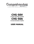
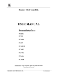
ENV-416S SQUARE WAVE
AVERSIVE STIMULATOR
USER’S MANUAL
DOC-097
Rev. 1.2
Copyright © 2009
All Rights Reserved
MED Associates, Inc.
P.O. Box 319
St. Albans, Vermont 05478
www.med-associates.com
MED ASSOCIATES INC.
ENV-416S AVERSIVE STIMULATOR
- ii -
MED ASSOCIATES INC.
ENV-416S AVERSIVE STIMULATOR
TABLE OF CONTENTS
Chapter 1 .............................................................................................. 1
Introduction ...................................................................................................... 1
Chapter 2 .............................................................................................. 2
ENV-416S Front Panel ........................................................................................ 2
Manual Operate Switch .................................................................................... 2
Unarmed/Armed Switch ................................................................................... 2
Output Current Adjust ..................................................................................... 2
Output Current Meter ...................................................................................... 3
Chapter 3 .............................................................................................. 4
ENV-416S Back Panel ......................................................................................... 4
High Voltage Output ........................................................................................ 4
Grid Output Connector ..................................................................................... 4
MED Control Connector .................................................................................... 4
TTL/ Switch Closure ........................................................................................ 5
25K Dummy Load V-out Jacks ........................................................................... 5
Power In........................................................................................................ 5
Chapter 4 .............................................................................................. 6
Operating Instructions ........................................................................................ 6
Adjusting the Output Current ............................................................................ 6
Operating Instructions ..................................................................................... 7
- iii -
MED ASSOCIATES INC.
ENV-416S AVERSIVE STIMULATOR
- iv -
MED ASSOCIATES INC.
ENV-416S AVERSIVE STIMULATOR
CHAPTER 1
Introduction
The ENV-416S provides a full range of 0-10 ma aversive stimulation produced by an
advanced solid-state current source. The design allows for a much safer lower source
voltage.
The unit delivers an adjustable two pole or scrambled square wave. The ENV-416S
features a 200 ms safety switch that can limit the aversive stimulation to a maximum of
200 ms, or the safety switch may be turned off if longer durations are desired.
For grid floor applications, the grid rod floor connects to the system via a standard DB-9
connector. For bi-polar applications, such as tail aversive stimulus electrodes, the
electrodes attach to the 3-prong connector on the back panel.
The unit has a self-contained power supply and can be controlled by a 28 VDC to ground
signal, a 5 volt TTL signal, or a remote switch closure, thus allowing maximum flexibility.
- 1 -
MED ASSOCIATES INC.
ENV-416S AVERSIVE STIMULATOR
CHAPTER 2
ENV-416S Front Panel
Figure 2.1 - ENV-416S Front Panel
Power Switch
When switched to the ON (1) position, the power switch lights up, indicating power has
been switched on to the circuit.
Manual Operate Switch
When this spring loaded switch is in its default (up) position, it allows the aversive
stimulator to be enabled by a MED 28 volt control signal, a TTL active low signal or a
switch closure (see below for a description of rear panel connections). When this switch
is toggled to the MANUAL OPERATE position, an internal operate signal enables the
aversive stimulator.
Unarmed/Armed Switch
When the UNARMED/ARMED is switched to the UNARMED position, the device will
not function. When the UNARMED/ARMED switch is set to the ARMED position and no
input is being received by the device, the aversive stimulus output is routed from the
rear panel high voltage output connector to the internal dummy load resistor and output
to the 25K-ohm LOAD Vout jacks on the rear panel.
The OUTPUT CURRENT meter will display the constant current output setting of the
aversive stimulator, which may be adjusted using the current adjust knob.
Output Current Adjust
This ten-turn locking knob varies the output current of the aversive stimulator.
- 2 -
MED ASSOCIATES INC.
ENV-416S AVERSIVE STIMULATOR
Output Current Meter
When the UNARMED/ARMED switch is in the UNARMED position, the meter will display a
reading of zero. When the UNARMED/ARMED switch is set to the ARMED position, the
meter displays the current through the internal dummy load. During an aversive
stimulus, the meter will display a reading of zero. The aversive stimulus current
administered is the same as what was displayed on the meter while adjusting the output
current.
200 ms Safety Switch
The 200ms Safety switch is used to turn an internal 200ms aversive stimulus limit timer
on or off. While the 200ms Safety switch is in the ON position, the maximum duration of
an aversive stimulus is internally set to 200 ms. The 200ms time limit cannot be user
adjusted. If an operate command inadvertently lasts longer than 200ms, the internal
safety override timer will limit the aversive stimulus duration to a maximum of 200ms.
If the safety switch is held in the OFF position (down), the internal 200ms time limit is
disabled and an aversive stimulus can be administered as long as the operate signal is
on.
- 3 -
MED ASSOCIATES INC.
ENV-416S AVERSIVE STIMULATOR
CHAPTER 3
ENV-416S Back Panel
Figure 3.1 - ENV-416S Back Panel
High Voltage Output
Use this 3-pin Cinch-Jones connector for aversive stimulus-delivery devices other than
the grid floor. This connection is activated via either a MED control signal or a TTL
switch closure.
Grid Output Connector
This DB-9 connector connects the aversive stimulus output to the grid floor. The output
of this connector provides scrambled aversive stimulus across the grid rods.
MED Control Connector
The MED Control 3-pin Molex connector should be connected to any available Output on
a Standard MED Connection Panel. The pin out of this connector is as follows:
Molex Pin #
Function
1
Not Used
2
Operate
3
+ 28 Volts
- 4 -
MED ASSOCIATES INC.
ENV-416S AVERSIVE STIMULATOR
TTL/ Switch Closure
For TTL operation, connect the (+) terminal to an active low TTL “operate” signal and
the (-) terminal to a TTL ground connection. Asserting the TTL operate signal low
enables the aversive stimulator.
For Switch Closure operation, connect the screw terminals to a closure device such as a
switch or relay. When the switch closure is made, the aversive stimulator is enabled.
NOTE: It is not recommended that the switch closure and the MED control signals be
used (on) at the same time. Use one or the other.
25K Dummy Load V-out Jacks
These .080” pin jacks allow the user to measure the voltage across the internal 25K-ohm
dummy load resistor.
The UNARMED/ARMED switch must be switched to the ARMED
position. If a measurement of the actual current during an aversive stimulus is desired,
a sampling resistor should be placed in series with the output and an oscilloscope could
be used to monitor the current. Contact the factory for further details.
Power In
This receptacle accepts a standard 110V/220V AC equipment power cord.
The
receptacle also contains a replaceable line fuse, as well a replacement fuse. To access
the fuse, remove the power cord and place a small straight blade screwdriver into the
slot under the fuse drawer. Slide the fuse drawer out to access the fuse.
NOTE: Use only factory recommended type replacement fuses for this unit. If in doubt,
contact the factory.
- 5 -
MED ASSOCIATES INC.
ENV-416S AVERSIVE STIMULATOR
CHAPTER 4
Operating Instructions
Adjusting the Output Current
The output aversive stimulus current is set by switching the UNARMED/ARMED switch to
ARMED and setting the 200ms Safety Switch to OFF. The OUTPUT CURRENT display
will now display the output current through the dummy load. Turn the output current
adjust knob until the desired output current is displayed.
The dummy load is a 25K-ohm internal load used as a reference for adjusting the output
current. Setting the safety switch to OFF disables the 200ms safety feature and allows
the internal circuitry to measure the output current accurately. The current displayed on
the meter is the amount of current that will be administered during the aversive
stimulus, regardless of the subjects’ impedance provided that the subjects’ impedance is
less than 25K-ohm.
Note that a maximum of 250V output is available.
maximum output current is:
So for a load of 25K-ohm the
250V / 25K = 10mA
As long as the impedance of the subject is 25K-ohm or less, the set current will be
administered. But, if the impedance of the subject is greater than 25K-ohm then the
desired aversive stimulus current may not be properly administered. For example, if the
impedance of the subject is 50Kohm and the output current is set to 10mA then the
maximum output current will be:
250V / 50K-ohm = 5mA
But, if the output current is set to 5mA for the same 50K load, the output current will be
5mA.
Use the following formula to calculate the maximum output current into a load
impedance greater than 25K-ohm:
Imax = 250V / Z
Where Imax is the maximum possible output current, 250V is the maximum output
voltage available, and Z is the impedance of the subject. Under normal use, the
subjects’ impedance should be less than 25K-ohm and the adjusted output current will
be properly administered.
- 6 -
MED ASSOCIATES INC.
ENV-416S AVERSIVE STIMULATOR
Operating Instructions
1. Prior to using the ENV-416S ensure that the output current is set to the desired level
and that the UNARMED/ARMED switch is set to UNARMED.
2. Connect the desired input (MED 28 volt control signal, a TTL active low signal or a
switch closure).
3. Verify that the 200 ms Safety switch is in the desired position.
4. Switch the UNARMED/ARMED switch to ARMED.
5. The OUTPUT CURRENT meter will display the actual output current setting.
6. When the input to the device is activated, the aversive stimulus will be administered
and the OUTPUT CURRENT display will read zero during the aversive stimulus.
- 7 -