1
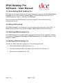
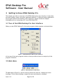
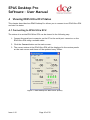
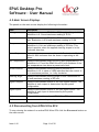
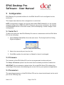
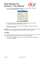
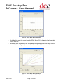
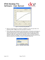
EPAS Desktop Pro Software User Manual Issue 1.10 EPAS Desktop Pro Software – User Manual Contents 1 Introduction 1.1 What is EPAS Desktop Pro? 1.2 About This Manual 1.3 Typographical Conventions 1.4 Getting Technical Support 2 Getting Started 2.1 System Requirements 2.2 Installing EPAS Desktop Pro 2.3 Uninstalling EPAS Desktop Pro 2.4 Using Online Help 2.5 Starting EPAS Desktop Pro 2.6 Exiting EPAS Desktop Pro 3 Getting to Know EPAS Desktop Pro 3.1 Tour of the EPAS Desktop Pro User Interface 3.2 Main Menu 3.3 Command Reference 4 Viewing EPAS Ultra ECU Status 4.1 Connecting to EPAS Ultra ECU 4.2 Main Screen Displays 4.3 Disconnecting from EPAS Ultra ECU 5 Configuration 5.1 Serial Port 5.2 Firmware 5.3 Parameters 5.4 Maps 6 Troubleshooting 7 Error Messages Issue 1.10 Page 2 of 20 4 4 4 5 5 6 6 6 7 7 7 7 8 8 8 9 10 10 11 11 13 13 13 13 14 18 19 EPAS Desktop Pro Software – User Manual Table of Figures Figure 1 - EPAS Desktop Pro Main Screen (Inactive) Figure 2 –EPAS Desktop Pro Main Menu Figure 3 - EPAS Desktop Pro Main Screen (Active) Figure 4 - Setup Serial Port Dialog Figure 5 - Setup Parameters Dialog Figure 6 - Setup Maps Dialog (No Maps) Figure 7 - Setup Maps Dialog (All Maps) Figure 8 - Setup Maps Dialog (One Map) Figure 9 - Setup Maps Dialog (Map Edit) Figure 10 - Edit Map Comment Dialog Issue 1.10 Page 3 of 20 8 8 10 13 14 15 15 16 17 17 EPAS Desktop Pro Software – User Manual 1 Introduction 1.1 What is EPAS Desktop Pro? PolyLogic’s EPAS Desktop Pro Software enables the operating parameters of the DC Electronics’ EPAS Ultra ECU to be viewed in real time. EPAS Desktop Pro also provides facilities for configuring and re-programming the EPAS Ultra ECU via the serial port of the host PC. With PolyLogic’s EPAS Desktop Pro Software you can: View real-time data for: Battery voltage Current consumption Applied steering torque Steering motor duty ECU box temperature Steering angle Control switch setting Digital input and output states Read ECU serial number, firmware version and system type Configure the EPAS Ultra ECU via the serial port of the host PC View and alter the relationship between torque input and motor duty for each control switch position Update the firmware of the EPAS Ultra ECU via the serial port of the host PC 1.2 About This Manual This User Manual is intended to complement the help files built into the EPAS Desktop Pro application. The chapters are presented in an order intended to help new users understand the program as quickly as possible. Be aware, however, that this manual and the program’s help file assume that you are comfortable using the Microsoft Windows 98/2000/Me/NT4/XP/Vista operating system. If you are new to Windows you may find the Windows Online Help file useful. To access Microsoft Windows Help choose Help from the start menu on your Windows desktop. Issue 1.10 Page 4 of 20 EPAS Desktop Pro Software – User Manual 1.3 Typographical Conventions Please be aware of the following typographical conventions when reading this manual: Menu items that you are instructed to choose appear with an arrow ( ) symbol separating each menu level. For example, if you if you are instructed to choose the Parameters command in the Setup menu it will appear as Setup Parameters. Where a button or other control needs to be clicked the name of the button or control will be shown in bold text. 1.4 Getting Technical Support For technical support with EPAS Desktop Pro please contact: [email protected] In addition, there are pages dedicated to support issues with PolyLogic’s products on the PolyLogic web site. The table below lists the ways to contact PolyLogic: Contact Method Address or Number Website: www.polylogic.co.uk Email: [email protected] Telephone: +44 (0) 5601 140733 Fax: +44 (0) 5601 140733 Mail: PolyLogic Limited 47 Old Forge Drive West Haddon Northampton NN6 7ET UK Issue 1.10 Page 5 of 20 EPAS Desktop Pro Software – User Manual 2 Getting Started EPAS Desktop Pro is supplied on a CD-ROM which is used to install the program onto the hard disk of your computer. 2.1 System Requirements Before attempting to install EPAS Desktop Pro, make sure that your computer meets the following minimum system requirements shown in the table below: Component Requirement Processor Pentium class processor or equivalent Operating System Microsoft Windows 98/Me/NT4/2000/XP/Vista Hard Disk Space 10Mb System Memory 32Mb (64Mb recommended) Other Drives CD-ROM Monitor/Display Super VGA (800 x 600) or higher resolution with 256 colours Serial Port One serial port or USB port with USB-serial adapter Pointing Device Microsoft Mouse or compatible pointing device 2.2 Installing EPAS Desktop Pro Before you can run EPAS Desktop Pro you must install it on the hard disk of your computer. Follow these steps to install the software: Switch on your computer and log on in the normal way. Insert the EPAS Desktop Pro CD into the CD drive. The EPAS Desktop Pro Setup Wizard dialog will appear automatically. Click Next. Choose the installation folder for the software and click Next. Click Next again to complete the installation. Click Close once the installation is complete. The installation process places shortcuts to EPAS Desktop Pro on the computer’s desktop and Start menu. NOTE: If the EPAS Desktop Pro installation process does not start automatically, you can start it manually by using My Computer or Windows Explorer to navigate to the contents of the CD and then double-clicking the file SETUP.EXE. Issue 1.10 Page 6 of 20 EPAS Desktop Pro Software – User Manual 2.3 Uninstalling EPAS Desktop Pro EPAS Desktop Pro can be removed from your computer by selecting the Add and Remove Programs option within Windows Control Panel. Find EPAS Desktop Pro in the list of installed software, select it, and then click Remove. This will remove the EPAS Desktop Pro software together with its shortcuts and configuration entries. 2.4 Using Online Help Once EPAS Desktop Pro is running you can view items in the Help menu at any time. To display the online Help file press choose Help Help Topics from the main menu. 2.5 Starting EPAS Desktop Pro Start EPAS Desktop Pro by either double clicking the shortcut on the computer’s desktop or by selecting Programs PolyLogic EPAS Desktop Pro from the Start button on the desktop’s toolbar. 2.6 Exiting EPAS Desktop Pro You can exit EPAS Desktop Pro using any of the following methods: Choose File Exit from the main menu, or Click the close button in the upper right corner of the title bar, or Press the key combination Alt + F4. Issue 1.10 Page 7 of 20 EPAS Desktop Pro Software – User Manual 3 Getting to Know EPAS Desktop Pro This chapter provides an overview of the EPAS Desktop Pro user interface. It describes the main window, menu, and other important features. To help you better understand the program and become familiar with its features, please review this chapter thoroughly prior to connecting a PC to an EPAS Ultra ECU. 3.1 Tour of the EPAS Desktop Pro User Interface When you start EPAS Desktop Pro the main program window appears as shown below. Figure 1 - EPAS Desktop Pro Main Screen (Inactive) At the top of the main program window a menu provides access to a majority of the program’s features. 3.2 Main Menu Figure 2 –EPAS Desktop Pro Main Menu The Main Menu (Figure 2), which is directly below the title bar, displays the menu headings. Click a menu heading to open the menu and choose a command. Issue 1.10 Page 8 of 20 EPAS Desktop Pro Software – User Manual Use either of the following methods to choose a menu command: Open the menu and click the command, or Open the menu, use the Up arrow or Down arrow key to highlight a command, and then press <Enter>. In addition, each menu may be opened by pressing the <Alt> key and then pressing the key associated with the required menu. Section 3.3 lists all the available menu commands. 3.3 Command Reference The following commands are available: Menu Command File Menu Exit Setup Menu Keyboard Shortcut Section Alt + F Alt + F, X 2.6 Alt + S Serial Port Alt + S, S 5.1 Firmware Alt + S, F 5.2 Parameters Alt + S, P 5.3 Maps Alt + S, M 5.4 Help Menu Alt + H Help Topics Alt + H, H - About Alt + H, A - Issue 1.10 Page 9 of 20 EPAS Desktop Pro Software – User Manual 4 Viewing EPAS Ultra ECU Status This chapter describes how EPAS Desktop Pro allows you to connect to an EPAS Ultra ECU and view its status. 4.1 Connecting to EPAS Ultra ECU The status of an active EPAS Ultra ECU can be viewed in the following way: 1. Connect the serial port connector on the PC to the serial port connector on the EPAS Ultra ECU using a suitable cable. 2. Click the Connect button on the main screen. 3. The current status of the EPAS Ultra ECU will be displayed in the various panels on the main screen and these will be updated every 500ms. Figure 3 - EPAS Desktop Pro Main Screen (Active) Issue 1.10 Page 10 of 20 EPAS Desktop Pro Software – User Manual 4.2 Main Screen Displays The panels on the main screen display the following information: Item Description Voltage Displays instantaneous EPAS Ultra ECU supply voltage in Volt. Resolution is 0.1V and maximum reading is 25.5V. Current Displays instantaneous EPAS Ultra ECU current consumption in Amp. Resolution is 0.5A and maximum reading is 25.5A. Torque Displays instantaneous applied steering torque in bits. Resolution is 1 bit and maximum reading is 255 bits. This value is positive when the applied steering torque is in the clockwise direction. Motor Duty Displays instantaneous motor duty in %. Resolution is 1%. A value of 100% indicates that the motor is operating at full power. Box Temperature Displays instantaneous EPAS Ultra ECU box temperature in ºC. Resolution is 1ºC and the EPAS Ultra ECU will shutdown if the box temperature rises above a preset safe limit. Switch Position Displays instantaneous steering control position in %. Resolution is 1%. A value of 100% indicates that the control is at its maximum position, i.e. fully clockwise. Steering Angle Displays instantaneous steering angle in bits. Resolution is 1 bit and maximum reading is 255 bits. Digital Outputs Displays instantaneous status of the four digital outputs. The function of each output is determined by the system configuration. Digital Inputs Displays instantaneous status of the two digital inputs. The function of each input is determined by the system configuration. S/N Unique 64-bit serial number of EPAS Ultra ECU. Code Firmware version and system type. 4.3 Disconnecting from EPAS Ultra ECU To stop viewing the status of an active EPAS Ultra ECU click the Disconnect button on the main screen. Issue 1.10 Page 11 of 20 EPAS Desktop Pro Software – User Manual NOTE: It is important to disconnect in this way, rather than just closing the EPAS Desktop Pro application, as otherwise the connection to the EPAS Ultra ECU will remain active and any attempt to reconnect will fail unless the EPAS Ultra ECU is reset first. Issue 1.10 Page 12 of 20 EPAS Desktop Pro Software – User Manual 5 Configuration EPAS Desktop Pro provides facilities for the EPAS Ultra ECU to be configured via the serial port. This chapter describes how this configuration is carried out. NOTE: Configuration changes can only be made whilst EPAS Desktop Pro is not actively communicating with an EPAS Ultra ECU. Disconnect any active connection, by clicking the Disconnect button on the main screen, before attempting to make changes to the configuration. 5.1 Serial Port To alter the serial port that EPAS Desktop Pro uses to communicate with the EPAS Ultra ECU do the following: 1. Choose Setup Serial Port from the main menu. The Setup Serial Port Dialog (Figure 4) appears. Figure 4 - Setup Serial Port Dialog 2. Select the new serial port from the list. 3. Click OK to update the serial port or Cancel to leave it unchanged. 5.2 Firmware The firmware of the EPAS Ultra ECU can be re-programmed via the serial port. The Setup Firmware option from the main menu has been provided to enable this. IMPORTANT: Do not attempt to upload a hex file to the EPAS Ultra ECU without first contacting DC Electronics and obtaining the correct file for your system and application. 5.3 Parameters The operating parameters of the EPAS Ultra ECU can be viewed and altered via the serial port in the following way: Issue 1.10 Page 13 of 20 EPAS Desktop Pro Software – User Manual 1. Select the Setup Parameters option from the main menu. The Setup Parameters dialog (Figure 5) is displayed. Figure 5 - Setup Parameters Dialog 2. The Setup Parameters dialog displays the current values of all the user configurable parameters of the EPAS Ultra ECU. 3. Make any changes that are required and click Apply or Cancel to leave the parameters unchanged. WARNING: Care must be observed when changing EPAS Ultra ECU parameters. Using the wrong values could damage both the EPAS Ultra ECU and the steering unit. 5.4 Maps The relationship between steering torque input and motor duty output for each control switch setting can be altered via the serial port in the following way: 1. Select the Setup Maps option from the main menu. The Setup Maps dialog (Figure 6) is displayed. Issue 1.10 Page 14 of 20 EPAS Desktop Pro Software – User Manual Figure 6 - Setup Maps Dialog (No Maps) 2. Click Read to read the maps from the EPAS Ultra ECU or Load to load map data from a disk file. 3. Once map data is available the Setup Maps dialog displays all five maps on the same set of axes (Figure 7). Figure 7 - Setup Maps Dialog (All Maps) Issue 1.10 Page 15 of 20 EPAS Desktop Pro Software – User Manual 4. Use the arrow buttons or the drop-down box in the top right-hand corner of the dialog to select the map to be edited (Figure 8). Figure 8 - Setup Maps Dialog (One Map) 5. When the Locked checkbox is not checked edit markers are displayed at 16 places along the map (Figure 9). Use the mouse to drag each of the markers until the required map shape is obtained. Note that each marker is constrained by the markers either side of it. Issue 1.10 Page 16 of 20 EPAS Desktop Pro Software – User Manual Figure 9 - Setup Maps Dialog (Map Edit) 6. When the map changes are complete click Write to write the map data to the EPAS Ultra ECU or Save to save the map data to a disk file. 7. When editing a map clicking the right mouse button in the graph area brings up a context menu that allows the comment associated with the map to be edited. When this menu option is selected the Edit Map Comment dialog (Figure 10) is displayed. Make any changes that are required and then click OK or Cancel to leave the comment unchanged. Note that these comments are only stored in the disk file and are not read from or written to the EPAS Ultra ECU. Figure 10 - Edit Map Comment Dialog Issue 1.10 Page 17 of 20 EPAS Desktop Pro Software – User Manual 6 Troubleshooting Problem I can’t connect to the EPAS Ultra ECU or read/write its parameters. Cause The EPAS Ultra ECU is not powered up. Action Turn on the Master switch, and the ignition switch (if necessary). Cause The serial lead is not connected. Action Connect the EPAS Ultra ECU to the serial port of the host computer using the correct cable and try again. Cause The lead is not making a good connection. Action Ensure both connectors are fully home and that the lead is not damaged in any way. Cause The serial port is not configured correctly. Action Choose Setup Serial Port from the main menu and select the correct serial port. If you are using a USB to serial adapter use Windows Device Manager to determine the COM port number. Cause A previous connection was not disconnected correctly. Action Reset EPAS Ultra ECU and try again. Issue 1.10 Page 18 of 20 EPAS Desktop Pro Software – User Manual 7 Error Messages One of the following error messages will be displayed whilst trying to connect to an EPAS Ultra ECU using EPAS Desktop Pro when the EPAS Ultra ECU fault light is lit: Message Error 100 : Low battery voltage Meaning The battery supply voltage has fallen below a preset threshold and the EPAS Ultra ECU cannot continue to operate safely. Message Error 101 : Torque sensor not connected Meaning The torque sensor is not responding either because it is faulty or because it is not connected correctly. Message Error 102 : Torque sensor fault Meaning The reading from the torque sensor is incorrect either because it is faulty or because it is not connected correctly. Message Error 103 : Current sensor fault Meaning The reading from the internal current sensor is incorrect. Message Error 104 : Motor power fault Meaning The power drawn when the motor power relay is energised is higher than expected. Message Error 105 : Motor not connected Meaning The power steering motor is not drawing enough current indicating that it may not be connected. Message Error 106 : Motor is shorted or stalled Meaning The power steering motor is drawing too much current indicating that it is either shorted or stalled. Message Error 107 : Clutch not connected Meaning The motor clutch is not drawing enough current when energised indicating that it may not be connected. Issue 1.10 Page 19 of 20 EPAS Desktop Pro Software – User Manual Message Error 108 : Clutch is shorted or stalled Meaning The motor clutch is drawing too much current when energised indicating that it is either shorted or stalled. Message Error 109 : Over current condition detected Meaning The internal current limit has been exceeded. Message Error 110 : Maximum safe temperature exceeded Meaning The box temperature has exceeded the maximum safe value. Issue 1.10 Page 20 of 20