1
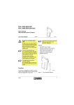
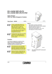
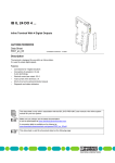
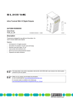
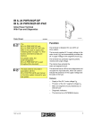
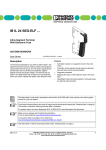
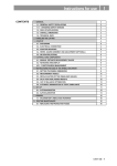
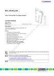
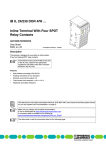
IB IL 24/230 DOR 4/W
INTERBUS Inline Terminal
With 4 Relay Changeover Contacts
Data Sheet 6326A
6 3 2 6 A 0 0 1
01/2002
This data sheet is only valid in association with the “Configuring and
Installing the INTERBUS Inline
Product Range” User Manual
IB IL SYS PRO UM E.
Function
The terminal is designed for use within an
INTERBUS Inline station. It has 4 relay changeover contacts that are electrically isolated.
The terminals can be used in the
SELV (low voltage) area and in the AC
area. Observe the appropriate conditions and safety notes when using the
terminal in the AC area.
6 3 2 6 A 0 0 2
Figure 1
IB IL 24/230 DOR 4/W
terminal with connector
Features
–
Safe isolation according to EN 50178
–
Electrically isolated connection for 4
actuators
–
Nominal current at the output: 3 A
–
Total current of the terminal: 4 x 3 A = 12 A
–
Diagnostic and status indicators
6326A
Please note that the connectors are
not supplied with the terminal. Please
refer to ordering data on page 18 to
order the appropriate connectors for
your application.
1
IB IL 24/230 DOR 4/W
Safety Notes for Inline Terminals Used in Areas Outside the
SELV (AC Area)
Only qualified personnel may carry out work on
the Inline terminals of the AC area.
Qualified personnel are people who, because of
their education, experience and instruction and
their knowledge of relevant standards, regulations, accident prevention and service conditions,
have been authorized by those responsible for
the safety of the plant to carry out any required
operations and who are able to recognize and
avoid any possible dangers.
(Definitions for skilled workers according to
EN 50110-1:1996).
The instructions given in this data sheet and
in the IB IL SYS PRO UM E User Manual must
be followed during installation and startup.
Technical modifications reserved.
Correct Usage
The terminal is only to be used within an Inline
station as specified in this data sheet and the INTERBUS Inline System Manual. Phoenix Contact accepts no liability if the device is used for
anything other than its designated use.
For general information on the
INTERBUS Inline product range, please refer to the “Configuring and Installing the INTERBUS Inline Product
Range” User Manual
IB IL SYS PRO UM E.
Dangerous voltage!
Dangerous voltage when switching
current circuits that do not meet the
requirements of the SELV.
Connecting and disconnecting the AC
terminals is only allowed if the power
supply is disconnected.
When working on the terminals and
wiring, always switch off the supply
voltage and ensure it cannot be switched on again.
2
6326A
IB IL 24/230 DOR 4/W
Installation Instructions and
Notes
Install the system according to the requirements of EN 50178.
Use grounded AC networks
Inline AC terminals must only be operated in grounded AC networks.
Read the User Manual
Please observe the installation guidelines in the IB IL SYS PRO UM E User
Manual, in particular the notes for the
low voltage area.
Special Features of the
IB IL 24/230 DOR 4/W Terminal
Up to 230 V can be switched using the
IB IL 24/230 DOR 4/W terminal.
Please note that the
IB IL 24/230 DOR 4/W terminal interrupts the voltage jumpers UM, US and
GND (24 V area) and L and N (120 V/
230 V areas). The main power must
be supplied using a power terminal
after the
IB IL 24/230 DOR 4/W, if required.
Switching Loads in the 230 V Area
To switch voltages outside the SELV area, an
AC area must be created corresponding to the
installation instructions in the User Manual.
Operation in an AC network:
Operate the terminal from a single
phase on an AC network.
Switching Voltages that are not Available in
the Segment
With the relay terminal it is possible to switch voltages that are not available in the segment in
which the terminal is used (e.g., switching of
230 V AC in a 24 V DC segment). In this case,
place a terminal (see “Ordering Data” on
page 18) before and after the
IB IL 24/230 DOR 4/W relay terminal.
See also "Connection Examples" on page 6.
6326A
3
IB IL 24/230 DOR 4/W
General Description
Local Diagnostic and Status Indicators
Des.
D
1
D
2
3
4
1,2,
3,4
D O R 4 /W
Color Meaning
Green Bus diagnostics
Yellow Output status indication
(relay energized)
Terminal Assignment for Each Connector
1
2
1 .1
1
1
2 .1
1 .2
2
2
2 .2
1 .3
3
3
1 .4
4
4
Terminal
Points
Assignment
1.1, 2.1
Not used
(no contact present)
1.2, 2.2
Relay N/C contact
1.3, 2.3
Relay main contact
1.4, 2.4
Relay N/O contact
The adjacent contacts 1.2/2.2, 1.3/2.3 and 1.4/
2.4 are jumpered in the connector
IB IL SCN-8-AC-REL.
2 .3
2 .4
6 3 2 6 A 0 0 3
Figure 2
IB IL 24/230 DOR 4/W
with appropriate connectors
Function Identification
Red with lightning bolt
Housing/Connector Color
Gray housing
Gray connectors
4
6326A
IB IL 24/230 DOR 4/W
Internal Circuit Diagram
IN T E R B U S
U
O P C
L
4
4
6 3 2 6 A 0 0 4
Figure 3
Internal wiring of the terminal points
Key:
OPC
INTERBUS protocol chip (bus logic
incl. voltage conditioning)
Other symbols are explained in
the IB IL SYS PRO UM E User
Manual.
LED
Terminal point, without metal contact
Relay
Isolated area
I/O area including relay contact isolated from logic area including coils
of the relay through "safe isolation"
according to EN 50178
6326A
5
IB IL 24/230 DOR 4/W
Connection Examples
Connecting Actuators
1
2
4
3
D
1
2
3
4
D O R 4 /W
1
N /C
c o n ta c t
M a in
c o n ta c t
2
1
2
1
2
1
2
1
1 1
1 1
1 1
1
2
2 2
2 2
2 2
2
3
3 3
3 3
3 3
3
4
4 4
4 4
4 4
4
N /O
c o n ta c t
N /O
c o n ta c t
M a in c o n ta c t
N /C c o n ta c t
6 3 2 6 A 0 0 5
Figure 4
Connection example of actuators
1 .2
N /C
c o n ta c t
1 .4
N /O
c o n ta c t
M a in
1 .3
c o n ta c t
5 6 6 3 A 0 0 9
Figure 5
6
Relay contacts for the output
6326A
IB IL 24/230 DOR 4/W
Switching Voltages That are not Available in
the Segment
1
2
When switching a 24 V channel in a
24 V area or a 230 V channel in a
230 V area the separating terminals
are not required.
3
D
1
Switching Voltages That are Available in the
Segment
U M
1
2
3
4
P W R
D O R 4 /W
1
2
1
2
1
1
2
2
1
2
1
2
1
2
1
1
2
2
1
2
3
IN
1
2
2
1
2
1
1 1
1 1
1 1
1 1
1 1
1 1
1 1
1 1
1 1
1 1
1 1
1
2
2 2
2 2
2 2
2 2
2 2
2 2
2 2
2 2
2 2
2 2
2 2
2
3
3 3
3 3
3 3
3 3
3 3
3 3
3 3
3 3
3 3
3 3
3 3
3
4
4 4
4 4
4 4
4 4
4 4
4 4
4 4
4 4
4 4
4 4
4 4
4
D
1
U M
2
3
4
P W R
D O R 4 /W
1
1
2
1
2
1
2
1
2
1
2
1
2
1
1
2
2
1
2
1
1 1
1 1
1 1
1 1
1 1
1 1
1 1
1 1
1 1
1
2
2 2
2 2
2 2
2 2
2 2
2 2
2 2
2 2
2 2
2
3
3 3
3 3
3 3
3 3
3 3
3 3
3 3
3 3
3 3
3
4
4 4
4 4
4 4
4 4
4 4
4 4
4 4
4 4
4 4
4
6 3 2 6 A 0 0 6
Figure 6
2
IN
Switching 230 V within a 24 V area
1
24 V area consisting of station head
and I/O terminals
2
IB IL 24/230 DOR 4/W terminal separated from the 24 V area using the according terminals
3
24 V area consisting of power terminal
and I/O terminals
See also "Special Features of the IB IL 24/
230 DOR 4/W Terminal" on page 3.
6 3 2 6 A 0 0 7
Figure 7
Switching 24 V within a 24 V area
1
24 V area consisting of station head
and I/O terminals
2
IB IL 24/230 DOR 4/W terminal
3
24 V area consisting of power terminal
and I/O terminals
Use the separating terminals, too, if
you want to switch a 24 V channel
within a 230 V area.
6326A
7
IB IL 24/230 DOR 4/W
Interference Suppression
Measures for Inductive Loads/
Switching Relays
Each electrical load is a combination of ohmic,
capacitive and inductive elements. When switching these loads a larger or smaller load is provided for the switching contact depending on the
weighting of the elements.
A
B
5 9 7 3 A 0 2 8
Figure 8
Contact protection (A), load protection (B)
In practice, mainly loads with large inductive portions, such as contactors, solenoid valves or motors are used. Due to the energy stored in the
coils, voltage peaks of up to several thousand
volts may occur when the system is switched off.
These high voltages cause an arc, which may
destroy the controlling contact through material
evaporation and material transfer.
If sized correctly, these circuit versions do not
differ greatly in their effectiveness. In general, a
protective measure should be implemented directly at the source of the interference. The following points indicate the advantages of load protection:
–
This rectangular type pulse beams electromagnetic pulses via a wide frequency area. Spectral
parts reach the MHz area with a great deal of power.
When the contact is open, the load is electrically isolated from the operating voltage.
–
It is not possible for the load to be activated
or to "stick" due to undesired operating currents, e.g., from RC elements.
–
Shutdown voltage peaks cannot be induced
in control lines that run in parallel.
To prevent such arcs from occurring protective
circuits must be provided for contacts/loads. In
general, different wiring options are available:
–
Protecting the contact
–
Protecting the load
–
Combination of both protection methods
8
Phoenix Contact provide various solutions for
the protective circuit in terminal format or in electronic housing (see CLIPLINE catalog or TRABTECH catalog). Additional information is available on request. Today most contact
manufacturers also offer diode, RC or varistor
elements, which can be snapped on. For solenoid valves, it is possible to insert connectors
with an integrated protective circuit.
6326A
IB IL 24/230 DOR 4/W
Circuit Versions
L o a d P r o te c tio n
D io d e
A d d tio n a l
D e la y
D e
In d
V o
L im
fin e d
u c tio n
lta g e
ita tio n
B ip o la r
E ffe c tiv e
A tte n u a tio n
+
U
L o a d
D
L o n g
Y e s (U
D
)
N o
A d v a n ta g e s /D is a d a v a n ta g e s
A d v a n ta g e s :
- e a s y im p le m e n ta tio n
- c o s t- e ffe c tiv e
- r e lia b le
- u n c r itic a l d im e n s io n in g
- lo w in d u c tio n v o lta g e
D is a d v a n ta g e s :
- a tte n u a tio n o n ly v ia lo a d r e s is to r
- lo n g o ff d e la y
S e r ie s c o n n e c tio n
d io d e /z e n e r d io d e
+
L o a d
U
M e d iu m
to
s h o rt
A d v a n ta g e s :
- u n c r itic a l d im e n s io n in g
Y e s (U
)
Z D
N o
Z D
S u p p r e s s o r d io d e
+
(~ ) (~ )
U
L o a d
Z D
M e d iu m
to
s h o rt
Y e s (U
Z D
)
Y e s
D is a d v a n ta g e s :
- a tte n u a tio n o n ly
a b o v e U Z D
A d v
- c o
- u n
- lim
- s u
a n ta g e s :
s t- e ffe c tiv e
c r itic a l d im e n s io n in g
ita tio n o f p o s itiv e p e a k s
ita b le fo r A .C . v o lta g e
D is a d v a n ta g e s :
- a tte n u a tio n o n ly
a b o v e U Z D
V a r is to r
+
(~ ) (~ )
L o a d
V D R
U
V D R
M e d iu m
to
s h o rt
Y e s (U
V D R
)
Y e s
A d
- h
- u
- s
v a n ta g
ig h p o w
n c r itic a
u ita b le
e s
e
l d
fo
:
r a b s o r p tio n
im e n s io n in g
r A .C . v o lta g e
D is a d v a n ta g e s :
- a tte n u a tio n o n ly
a b o v e U V D R
5 6 6 3 A 0 2 9
6326A
9
IB IL 24/230 DOR 4/W
RC Circuit Versions
RC Series Connection:
A d d itio n a l
O ff
D e la y
L o a d P r o te c tio n
D e
In d
V o
L im
fin e d
u c tio n
lta g e
ita tio n
B ip o la r
E ffe c tiv e
A tte n u a tio n
A d v a n ta g e s :
- H F a tte n u a tio n
- s u ita b le fo r A .C
- le v e l- in d e p e n d
- r e a c tiv e - c u r r e n
R /C c o m b in a tio n
+
(~ ) (~ )
R
U
L o a d
M e d iu m
to
s m a ll
R C
A d v a n ta g e s /D is a d v a n ta g e s
N o
v ia p o w e r s to r a g e
. v o lta g e
e n t a tte n u a tio n
t c o m p e n s a tin g
Y e s
D is a d v a n ta g e s :
- e x a c t d im e n s io n in g r e q u ir e d
- h ig h in r u s h c u r r e n t
C
5 6 6 3 A 0 3 0
Sizing:
–
Capacitor:
C ≈ Lload / 4 × Rload2
–
Resistor:
R ≈ 0.2 × Rload
RC Parallel Connection With Series Diode
A d d itio n a l
O ff
D e la y
L o a d P r o te c tio n
D e
In d
V o
L im
fin e d
u c tio n
lta g e
ita tio n
B ip o la r
E ffe c tiv e
A tte n u a tio n
A d
- H
- le
- C
R /C c o m b in a tio n w ith d io d e
+
(~ ) (~ )
U
L o a d
R C
M e d iu m
to
s m a ll
C
A d v a n ta g e s /D is a d v a n ta g e s
N o
Y e s
v a n ta
F a tte
v e l- in
u rre n
g e s :
n u a tio n v ia p o w e r s to r a g e
d e p e n d e n t a tte n u a tio n
t in v e r s io n n o t p o s s ib le
D is a d v a n ta g e s :
- e x a c t d im e n s io n in g r e q u ir e d
- o n ly s u ita b le fo r D .C . v o lta g e
R
5 6 6 3 A 0 3 1
Sizing:
–
Capacitor:
C ≈ Lload / 4 × Rload2
–
Resistor:
R ≈ 0.2 × Rload
10
6326A
IB IL 24/230 DOR 4/W
Switching AC/DC Loads
Switching Large AC Loads
When switching large AC loads, the relay can be
operated up to the specified maximum values for
switching voltage, current and power. The arc,
which occurs during shutdown, depends on the
current, voltage and phase angle. This shutdown arc switches off automatically the next
time the load current passes through zero.
1 0 0 0
V
U
1 0
In applications with an inductive load, an effective protective circuit must be provided, otherwise the life of the system will be reduced considerably.
In applications with lamp loads or capacitive
loads the current peak should not exceed 6 A
when switching on the load. This guarantees a
lifetime of the IB IL 24/230 DOR 4/W terminal as
high as possible.
Switching Large DC Loads
In DC operation, a relay can switch a relatively
low current compared with the maximum permissible AC current. This maximum direct current value is also highly dependent on the voltage and is determined in part by constructive
conditions, such as the contact distance and
contact opening speed.
The corresponding current and voltage values
are shown in the example in Figure 9.
1 0 0
1
0 ,1
A 1 0
1
I
5 6 6 3 A 0 1 3
Figure 9
DC load limiting curve (relay
REL-SNR-1XU/G 5 GOLD LIEG)
I
Switching current in A
U
Switching voltage in V
Definition of the load limiting curve: For 1000
cycles, no constant arc should occur with a burning life of > 10 ms.
An unattenuated inductive load further reduces
the values given here for switching currents. The
energy stored in the inductivity can cause an arc
to appear which passes on the current via the
open contacts. Using an effective contact protective circuit, the same currents can be switched as for an ohmic load and the life of the relay
contacts is the same.
If higher DC loads than permitted are to be switched, several contacts can be switched in parallel.
Additional technical data is available on request.
6326A
11
IB IL 24/230 DOR 4/W
Programming Data
ID code
BDhex (189dec)
Length code
41hex
Process data channel
4 bits
INTERBUS Process Data
Assignment of the Terminal Points for the
OUT Process Data
Input address area
0 bits
Output address area
4 bits
(Byte.bit)- Bit
view
Parameter channel
(PCP)
0 bits
Assignment
Register length (bus)
4 bits
Status
indicator
Slot
0.3 0.2 0.1 0.0
4
3
2
1
N/C contact
1.2 1.2 1.2 1.2
Main contact
1.3 1.3 1.3 1.3
N/O contact
1.4 1.4 1.4 1.4
LED
4
3
2
1
If the bits are set to 1, the appropriate
connector is closed.
The LEDs light up if the appropriate
connector is closed.
For the assignment of the bit view to
your control or computer system, please refer to the data sheet
DB GB IBS SYS ADDRESS,
Part No. 90 00 99 0.
12
6326A
IB IL 24/230 DOR 4/W
Technical Data
General Data
Order Designation
IB IL 24/230 DOR 4/W
Order No.
28 36 42 1
Housing dimensions (width x height x depth)
48.8.2 mm x 120 mm x 71.5 mm
(1.921 in. x 4.724 in. x 2.815 in.)
Weight
138 g (without connector)
Operating mode
Process data operation with 4 bits
Connection method for actuators
To an electrically isolated relay changeover contact
Permissible temperature (operation)
-25°C to +55 °C (-13°F to +131°C)
Permissible temperature (storage/transport)
-25°C to +85°C (-13°F to +185°F)
Permissible humidity (operation)
75%, on average, 85%, occasionally
In the range from -25°C to +55°C (-13°F to +131°F) appropriate measures against increased humidity (> 85%) must be taken.
Permissible humidity (storage/transport)
75%, on average, 85%, occasionally
For a short period, slight condensation may appear on the housing if, for example, the
terminal is brought into a closed room from a vehicle.
Permissible air pressure (operation)
80 kPa to 106 kPa
(up to 2000 m [6561.680 ft.] above sea level)
Permissible air pressure (storage/transport)
70 kPa to 106 kPa
(up to 3000 m [9842.520 ft.] above sea level)
Degree of protection
IP 20 according to IEC 60529
Mechanical Requirements (Deviation From the Inline Specification)
Vibration test
Sinusoidal vibrations according to
IEC 60068-2-6; EN 60068-2-6
2g load, 2 h for each space direction
Shock test according to
IEC 60068-2-27; EN 60068-2-27
2g load over 11 ms, half sinusoidal wave,
three shocks in each space direction and
orientation
6326A
13
IB IL 24/230 DOR 4/W
Interface
INTERBUS local bus
Through data routing
Power Consumption
Communications power
7.5 V
Current consumption from the local bus
22 mA / 187 mA
Power consumption from the local bus
0.17 W / 1.4 W
Supply of the Module Electronics and I/O Through Bus Terminal/Power Terminal
Connection method
Through potential routing
Relay Output
Number
4
Contact material
AgSnO2, hard gold-plated
Contact resistance
50 mΩ at 100 mA/6 V
Limiting continuous current
(at maximum ambient temperature)
3A
Maximum switching voltage
253 V AC, 250 V DC
Maximum switching power (AC/DC)
750 VA (see derating)
Minimum load
5 V; 10 mA
Switching current at 30 V DC
3A
Switching current at 250 V DC
0.15 A
Maximum inrush current peak for lamp loads and 6 A for T = 200 µs
capacitive loads
See also table "Maximum Switching Current for Ohmic Load Depending on the Switching
Voltage" on page 16.
Nominal power consumption of the coil
(at 20 °C [68°F])
330 mW from the 7.5 V supply
Resistance of the coil (at 20 °C [68°F])
119 Ω ± 12 Ω
Maximum switching frequency (without load)
1200 cycles/minute
Maximum switching frequency (at nominal load) 6 cycles/minute
Response delay
5 ms, typical
Chatter time
5 ms, typical
Release time
6 ms, typical
14
6326A
IB IL 24/230 DOR 4/W
Relay Output (Continued)
Mechanical life
2 x 10⁷ cycles
Electrical life
105 cycles
(at 20 cycles/minute)
Common potentials
All contacts electrically isolated
6326A
15
IB IL 24/230 DOR 4/W
Maximum Switching Current for Ohmic Load Depending on the Switching Voltage
Switching Voltage (V DC)
Switching Current (A)
10
3.0
20
3.0
30
3.0
40
1.0
50
0.4
60
0.3
70
0.26
80
0.23
90
0.215
100
0.2
150
0.18
200
0.165
250
0.155
Load Current (IL in A) as a Function of the Switching Voltage (Uswitch in V)
3
A
2 .5
IL
2
1 .5
1
0 .5
0
1 0
2 0
3 0
4 0
5 0
6 0
7 0
8 0
9 0
1 0 0
1 5 0
U
2 0 0 V 2 5 0
S w itc h
5 6 6 3 A 0 0 4
16
6326A
IB IL 24/230 DOR 4/W
Maximum Switching Current Depending on the Temperature (for Alternating Voltage)
At a switching current of 3 A the switching voltage for alternating voltage can be up to
253 V AC. Observe the derating.
Load Current (IL in A) as Function of Ambient Temperature (TU in °C)
3
A
2 ,5
IL
2
1 ,5
1
0 ,5
0
1 0
2 0
3 0
4 0
4 5
T
5 0 ° C 5 5
U
6 3 2 6 A 0 0 8
Power Dissipation
Formula to Calculate the Power Dissipation in the Terminal
PTOT = PBUS + (PREL) + PL
PTOT = 0.17 W + 4 x (0.31 W) + IL2 x 0.04 Ω
For a N/C contact, the term PREL in the formula does not apply.
Where
PTOT
PBUS
PREL
PL
IL
Total power dissipation of the terminal
Power dissipation through the bus operation
Power dissipation of the relay coil
Power dissipation through the load current via the contacts
Load current of the output
Power Dissipation of the Housing Depending on the Ambient Temperature
PGEH = 2.7 W
-25 °C < TU ≤ +25 °C
PGEH = 2.7 W - ((TU - 25 °C) x 0.02 W/°C)
+25 °C < TU ≤ +55 °C
Where
PHOU
TU
6326A
Permissible power dissipation of the housing
Ambient temperature
17
IB IL 24/230 DOR 4/W
Safety Devices
None
Error Messages to the Higher-Level Control or Computer System
None
Air and Creepance Distances (According to EN 50178, VDE 0109, VDE 0110)
Isolating Distance
Air Distance
Creepance
Distance
Test Voltage
Relay contact/bus logic
≥ 5.5 mm
(0.217 in.)
≥ 5.5 mm
(0.217 in.)
4 kV, 50 Hz, 1 min
Contact/contact
≥ 3.1 mm
(0.122 in.)
≥ 3.1 mm
(0.122 in.)
1 kV, 50 Hz, 1 min
Contact/PE
≥ 3.1 mm
(0.122 in.)
≥ 3.1 mm
(0.122 in.)
1 kV, 50 Hz, 1 min
Ordering Data
Description
Order Designation
Order No.
Terminal with 4 digital relay outputs
IB IL 24/230 DOR 4/W
28 36 42 1
Connector with six connections using the
spring-clamp method (gray, w/o color print);
Package unit: 10 pieces
IB IL SCN-8-AC
27 40 29 0
Terminals for separating the relay terminal
(separating different voltage areas);
Package unit: 1 set (2 pieces)
IB IL DOR LV-SET
27 42 64 1
Connector for IB IL DOR LV-SET;
Package unit: 1 set (2 pieces)
IB IL DOR LV-PLSET
27 42 66 7
“Configuring and Installing the INTERBUS Inline
Product Range” User Manual
IB IL SYS PRO UM E
27 43 04 8
18
6326A
IB IL 24/230 DOR 4/W
6326A
19
© Phoenix Contact 01/2002 Technical modifications reserved TNR 90 09 63 4
IB IL 24/230 DOR 4/W
Phoenix Contact GmbH & Co. KG
Flachsmarktstr. 8
32825 Blomberg
Germany
+ 49 - (0) 52 35 - 3-00
+ 49 - (0) 52 35 - 3-4 12 00
www.phoenixcontact.com
Worldwide Locations:
www.phoenixcontact.com/salesnetwork
20
6326A