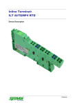
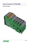
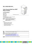
Download Device description
Transcript
Inline terminal with two SPDT (Form C) relays: ILT 24/48 DOR2/W Device description Preliminary Disclaimer / Imprint This manual is intended to provide support for installation and usage of the device. The information is believed to be accurate and reliable. However, SysMik GmbH Dresden assumes no responsibility for possible mistakes and deviations in the technical specifications. SysMik GmbH Dresden reserves the right to make modifications in the interest of technical progress to improve our modules and software or to correct mistakes. We are grateful to you for criticism and suggestions. Further information (device description, available software) can be found on our homepage www.sysmik.de. Please ask for latest information. SysMik disclaims all warranties in case of improper use or disassembly and software modifications not described in this document or when using improper or faulty tools. Commissioning and operation of the device by qualified personnel only. All applicable regulations have to be observed. SysMik® and the SysMik logo are registered trademarks of SysMik GmbH Dresden. IPOCS™ is © trademark of SysMik GmbH Dresden. "Networking Together!" is subject to copyright of SysMik GmbH Dresden. All other trademarks mentioned in this document are registered properties of their owners. These and further trademarks are used in this document but not marked for better readability. No part of this document may be reproduced or modified in any form without prior written agreement with SysMik GmbH Dresden. Copyright © 2014 by SysMik GmbH Dresden SysMik GmbH Dresden Tel + 49 (0) 351 – 4 33 58 – _0 Bertolt-Brecht-Allee 24 Fax + 49 (0) 351 – 4 33 58 – 29 01309 Dresden E-Mail (Sale) E-Mail (Support) Germany 2 Homepage sysmik.de [email protected] [email protected] www.sysmik.de ILT 24/48 DOR2/W Contents Contents Device description 1 Contents 3 1 Description 4 2 Order information 4 3 Technical data 5 4 Special fatures of the terminal 9 5 Local diagnostic and status indicators and terminal point assignment 10 6 Internal circuit diagram 11 7 Connection examples 12 8 Interference Suppression Measures on Inductive Loads/Switching Relays 14 ILT 24/48 DOR2/W sysmik.de 3 Description / Order information 1 Description The terminal is designed for use within an Inline station. It has two SPDT (form C) relay contacts, which are independent of each other. ATTENTION: Danger from undefined system state! By default, the relay contact positions of the terminal are not defined. Power cycle (on/off) the terminal completely before connecting the segment voltage in order to avoid undesirable system states. Note: This device description is only valid in association with the IL SYS INST UM user manual or the Inline system manual of the specifically used bus system. Make sure you always use the latest documentation – it can be downloaded at www.sysmik.de. Note: The terminal must only be used in the SELV area (up to 50 V AC or 120 V DC, maximum). Features Two SPDT (Form C) relays Floating connections for two actuators Nominal current of the output: 2 A Total current of the terminal: 4 A Diagnostic and status indicators Segment voltage US 2 Order information Description Type Terminal with two digital relay outputs; including ILT 24/48 DOR2/W connector and labeling field Part number Pcs./Pkt. 1225-100505-01-2 1 Optional Add-Ons (Purchase via Phoenix Contact): Description Type Part number Pcs./Pkt. User Manual: ‚Configuring and Installing the INTERBUSInline Product Range‘ IL SYS PRO UM E 2743048 1 4 sysmik.de ILT 24/48 DOR2/W Technical data 3 Technical data General data Housing dimensions (width x height x depth) 12,2 mm x 120 mm x 71,5 mm (0.480 in x 4.724 in. x 2.815 in.) Weight 48 g (without connector), 63 g (incl. connector) Operating mode Process data mode with 2 bits Connection method for actuators To two floating relay changeover contacts Permissible temperature (operation) -25 °C to +55 °C (-13°F to +131°F) Permissible temperature (storage/transport) -25 °C to +85 °C (-13°F to +185°F) Permissible humidity (operation) 75 % on average, 85 % occasionally In the range from -25°C to +55°C (-13°F to +131°F) appropriate measures against increased humidity (> 85 %) must be taken. Zulässige Luftfeuchtigkeit (Lagerung/Transport) 75 % on average, 85 % occasionally For a short period, slight condensation may appear on the outside of the housing if, for example, the terminal is brought into a closed room from a vehicle. Permissible air pressure (operation) 80 kPa to 106 kPa (up to 2000 m [6562 ft.] above sea level) Permissible air pressure (storage/transport) 70 kPa to 106 kPa (up to 3000 m [9843 ft.] above sea level) Degree oft protection IP20 according to IEC 60529 Power consumption Communications power 7,5 V DC Current consumption from the local bus 30 mA Power consumption from the local bus 0,23 W Supply of the Module Electronics and I/O Through Bus Terminal/Power Terminal Connection method ILT 24/48 DOR2/W Trough potential routing sysmik.de 5 Technical data Relay output Number 2 Contact material AgSnO2, hard gold-plated Contact resistance 75 mΩ Limiting continuous current (at maximum ambient temperature) 2A Maximum switching voltage 50 V AC, 120 V DC Maximum switching power (AC/DC) 60 W, 62,5 VA (ohmic load) Minimum load 10 mV DC; 10 µA Switching current at 30 V DC 2A Switching current at 60 V DC 1,0 A Maximale Einschaltstromspitze bei Lampenlasten 6 A für T = 200 µs und kapazitiv wirkenden Lasten See also the Table entitled "Maximum Switching Current for Ohmic Load Depending on the Switching Voltage" Nominal power consuption oft the coil (at 20 °C [68 °F]) 200 mW, bistable relay, no power in the switched state Resistance of the coil (at 20 °C [68 °F]) 178 Ω ± 10 % Maximum switching frequency (without load) 1 Hz Maximum switching frequency (with nominal load) 1 Hz Response delay 20 ms, typical Bouncing time 4 ms with on and off Release time 20 ms, typical Mechanical life 10 cycles Electrical life (30 V DC, 1 A) 2 x 10 cycles Common potentials All contacts floating 6 8 5 sysmik.de ILT 24/48 DOR2/W Technical data Maximum Switching Current for Ohmic Load Depending on the Switching Voltage Switching voltage (V DC) Switching current (A) 10 2,0 20 2,0 30 2,0 60 1,0 Load current (IL in A) as a function of switching voltage (USwitch in V) 1 … DC, ohmic load 2 … AC, ohmic load 4 Number oft operations (N x 10 ) as a funktion of load current (IL in A) 1 … 30 V DC, ohmic load 2 … 120 V AC, ohmic load Power dissipation Formula to calculate the power dissipation of the terminal PEL = PBUS + PL Where: PEL Total power dissipation in the terminal PBUS Power dissipation through bus operation PL Power dissipation through the load current via the contacts n Index of the number of loaded outputs n = 1 to 2 m Number of relays with controlled coil ILn Load current of the output n ILT 24/48 DOR2/W sysmik.de 7 Technical data Power Dissipation of the Housing Depending on the Ambient Temperature PHOU = 1,2 W PHOU = 1,2 W - ((TU -25 °C) x 0,02 W/°C) where: PHOU permissible power dissipation oft the housing TA ambient temperature -25 °C < TU ≤ +25 °C +25 °C < TU ≤ +55 °C Derating when using the N/O contact Ambient temperature TA Power dissipation of the housing Maximum load current (100 % simultaneity) Maximum load current (50 % simultaneity) 40 °C 0,9 W 2,0 A 2,0 A 55 °C 0,6 W 1,0 A 2,0 A Safety equipment none Error messages to the higher level control or computer system none Air and creepage distances (according to EN 50178, VDE 0109, VDE 0110) Isolating distance Air distance Creeping dist. Test voltage Relay contact/bus logic ≥ 1,5 mm ≥ 1,5 mm 4 kV, 50 Hz, 1 min. Contact/contact ≥ 1,5 mm ≥ 1,5 mm 1 kV, 50 Hz, 1 min. Contact/PE ≥ 3,1 mm ≥ 3,1 mm 1 kV, 50 Hz, 1 min. Relay/relay keine 8 sysmik.de ILT 24/48 DOR2/W Special features 4 Special fatures of the terminal Switching a Voltage Equal to the Segment Voltage The potential US is available at the terminal points 1.1 and 1.2. Inserting a jumper between 1.1 and 1.3 or 2.1 and 2.3 enables connecting the segment voltage potential to the main contact of the relevant relay in order to switch the load in a non-floating manner. If no jumpers are inserted, switching the load can also be floating. Switching a Voltage Unequal to the Segment Voltage – Different DC voltages Distance terminals are not required. Inserting a jumper is not useful and not permitted. It is only permitted to switch the load in a floating manner. If the switch contact potentials and the segment circuit potential are two different DC circuits, Phoenix Contact recommends using a ground connection between the two power supply units. Switching an AC voltage within a DC segment circuit Distance terminal must be used. The distance terminals interrupt the potential jumpers. As a result, no segment voltage is present at the terminal points 1.1 and 2.1. It is only possible to switch the connected load in a floating manner. When switching voltages outside the SELV area, use the Inline terminals ILT 24/230 DOR 1/W or ILT 24/230 DOR 4/W ein. ILT 24/48 DOR2/W sysmik.de 9 Diagnostic and status indicators / Terminal assignment 5 Local diagnostic and status indicators and terminal point assignment Local diagnostic and status indicators Local diagnostic and status indicators Des. Color Meaning D green 1 yellow 2 yellow Diagnostics Output status indicator (relay energized) Output status indicator (relay energized) Terminal point assignment per each connector Terminal point Assignment 1.1, 2.1 Segment voltage US 1.2 N/C contact oft relay 1 1.3 Main contact oft relay 1 1.4 N/O contact oft relay 1 2.2 N/C contact oft relay 2 3.3 Main contact oft relay 2 2.4 N/O contact oft relay 2 Fig. 1: Terminal with appropriate connector Functional identification Pink Housing / connector color Green housing Green connector, without color print 10 sysmik.de ILT 24/48 DOR2/W Circuit diagram 6 Internal circuit diagram Fig. 2: Internal wiring of the terminal points Key: Protocol chip (-bus logic including voltage conditioning) Relay, SPDT (Form C) LED Electrically isolated area: I/O area including relay contact isolated from the logic area including the relay coil Note: Other symbols used are explained in the IL SYS INST UM E user manual or in the manual oft the used bus system. ILT 24/48 DOR2/W sysmik.de 11 Connection examples 7 Connection examples Connecting actuators A … Floating actuator connection B … Non-floating actuator connection Fig. 3: Typical connection oft actuators 12 Fig. 4: Output relay form C contacts sysmik.de ILT 24/48 DOR2/W Connection examples Switching voltages that are not available in the segment Switching voltages that are available in the segment Fig. 5: Switching 48 V within a 24-V-area Fig. 6: Switching 24 V within a 24-V-area 1 24-V-area consisting of bus terminal and I/O terminals 1 24-V-area consisting of bus terminal and I/O terminals 2 ILT 24/48 DOR 2/W terminal separated from the 24-V-area by distance terminals 2 ILT 24/48 DOR 2/W terminal 3 24-V-area consisting of a power terminal and I/O terminals 3 24-V-area consisting of I/O terminals or a power terminal and I/O terminals See also ‚Special features of the terminal‘! As the distance terminals interrupt all the potential jumpers, US is not available at the terminal points 1.1 and 2.1 in this case. In this case the connected load can only be switched in a floating manner. ILT 24/48 DOR2/W sysmik.de Distance terminals are not required when switching e.g., a 24-V-channel within a 24-Varea! When using several ILT 24/48 DOR 2/W terminals SysMik recommends creating a separate main circuit with separate supply! 13 Interference suppression 8 Interference Suppression Measures on Inductive Loads/Switching Relays Each electrical load is a mixture of ohmic, capacitive, and inductive elements. Depending on the proportion of the element, switching these loads results in a larger or smaller load on the switch contact. In practice, loads are generally used with a large inductive element, such as contacts, solenoid valves, motors, etc. Due to the energy stored in the coils, voltage peaks of up to several thousand volts may occur when the system is switched off. These high voltages cause an arc, which may destroy the controlling contact through material evaporation and material transfer. This pulse, which is similar to a square wave pulse, emits electromagnetic pulses over a wide frequency range with a large amount of power and with spectral elements reaching several MHz. To prevent such arcs from occurring it is necessary to fit the contacts/loads with protective circuits. The following protective circuits can be used: Contact protective circuit Load protective circuit Combination of both protective circuits. Bild 7: Contact protective circuit (A), Load protective circuit (B) If sized correctly, these circuit versions do not differ greatly in their effectiveness. In principle, a protective measure should be directly implemented at the source of the interference. The following points speak in favor of a load protective circuit: When the contact is open, the load is electrically isolated from the operating voltage. It is not possible for the load to be activated or to "stick" due to undesired operating currents, e.g., from RC elements. Shutdown voltage peaks cannot be coupled in control lines that run in parallel. Today the majority of contactor manufacturers offer diode, RC or varistor elements that can be snapped on. For solenoid valves, connectors with an integrated protective circuit can be used. 14 sysmik.de ILT 24/48 DOR2/W Interference suppression Circuit versions ILT 24/48 DOR2/W sysmik.de 15 Interference suppression RC circuit versions: RC connected in series Sizing: Capacitor: C ≈ LLoad / 4 × RLoad Resistor: R ≈ 0,2 × RLoad 2 RC Parallelcircuit with series diode Sizing: Capacitor: C ≈ LLoad / 4 × RLoad Resistor: R ≈ 0,2 × RLoad 16 2 sysmik.de ILT 24/48 DOR2/W Interference suppression Switching AC/DC Loads Switching Large AC Loads When switching large AC loads, the relay can be operated up to the corresponding maximum values for switching voltage, current, and power. The arc that occurs during shutdown depends on the current, voltage, and phase angle. This shutdown arc switches off automatically the next time the load current passes through zero. In applications with an inductive load, an effective protective circuit must be provided, otherwise the life of the system will be reduced considerably. To prolong the life of the ILT 24/48 DOR 2/W terminal as much as possible when using lamp loads or capacitive loads, the current peak must not exceed 2 A when the load is switched on. Switching Large DC Loads In DC operation, a relay can only switch a relatively low current compared with the maximum permissible alternating current. This maximum direct current value is also highly dependent on the voltage and is determined in part by design conditions, such as the contact distance and contact opening speed. The corresponding current and voltage values are shown using the example in Figure 8 I Switching current in A U Switching voltage in V Definition of the load limiting curve: For 1000 cycles, no constant arc should occur with a burning life of >10 ms. Fig. 8: DC load limiting curve (REL-SNR-1XU/G 5 GOLD LIEG relay) An unattenuated inductive load further reduces the values for switching currents given here. The energy stored in the inductor can cause an arc to occur, which forwards the current via the open contacts. Using an effective contact protective circuit, the same currents can be switched as for an ohmic load and the life of the relay contacts is the same. If it is permitted to switch higher DC loads, several relay contacts can be switched in parallel. Additional technical data is available on request. ILT 24/48 DOR2/W sysmik.de 17


