1
ProComSol, Ltd
DevCom2000 PDA User Manual
QUICK START
DevCom2000 PDA uses Device Descriptions (DDs) to access data stored in the memory of the smart field device.
These DDs are developed by the manufacturer for their products and, in turn, distributed by the HART
Communication Foundation (HCF) worldwide. The latest DDs are included as part of the DevCom2000 PDA
installation. Visit the HCF website (www.hartcomm.org) or the ProComSol website (www.procomsol.com) for
update information.
The following steps will allow you to install and quickly begin using DevCom2000 PDA:
Step 1: Install the DevCom2000 PDA application
Insert the DevCom2000 PDA SD Card into the SD slot of the PDA. Place the PDA in its cradle connected to your
PC. Insert the DevCom2000 PDA installation CD into the CD drive on your computer. The DevCom2000 PDA
installation will automatically start and guide you through the installation process. Install DevCom2000 PDA in its
default location and enter the Serial Number that was supplied with your copy of the DevCom2000 PDA software.
If the installation program does not begin automatically, please go to StartRun and enter “CDRom drive
letter”:\setup.exe. This will begin the installation program. After the install is finished on the PC, select “SD Card”
on the PDA to finish installation. See Section 4.2 for details.
Step 2: Connect the communication interface
Connecting to a HART device requires special interface hardware to be attached to your computer. These
interfaces ("HART Modems") are available from ProComSol, Ltd and other sources. The interface should be
connected and configured (COM8 default). The preferred interface is a Bluetooth HART Modem - ProComSol,
Ltd model HM-BT-BAT or HM-BT-VIN. See Section 4.4 for details.
Step 3: Connect to the field device
Find a connection point for the device’s 2-wire 4-20mA loop you wish to communicate with. For communications
you must have a suitable load resistance or a 250Ω resistor must be placed in series with the device. Using the clips
from the HART interface, connect to the HART device. While the HART Communication signal is available
anywhere along the 4-20mA wiring, it is often easiest to connect across the field device's terminals (caution should
be observed when working in a hazardous area, many PDA’s are not rated for intrinsic safety and should only be
connected in a safe area).
Step 4: Activate DevCom2000 PDA
Launch DevCom2000 PDA by selecting the DevCom2000 PDA icon from the Start menu.
You will now be asked to Activate DevCom2000 PDA. You can use it for 30 days before you need to Activate it.
Select “No” to continue in Demo mode. Activation only needs to occur once. See Section 4.3 for details.
Operating DevCom2000 PDA is similar to working with Windows Explorer. DevCom2000 PDA communicates
to the field device, establishes a connection and learns its identity. Once DevCom2000 PDA knows its identity,
DevCom2000 PDA locates the device's DD and loads it. From this point forward operation of DevCom2000 PDA
is determined by the DD provided by the product's manufacturer. If a DD for the device is not present, a generic
DD will be used.
MAN-1017 07/15/08
Page 1
ProComSol, Ltd
DevCom2000 PDA User Manual
Step 5: Browse the Device
By default, DevCom2000 PDA will open the Browser window. The organization of the data in this explorer-style
window is dictated by the device DD. The top tree-pane of this window shows the logical groups of field device
data. These are called "Menus". The bottom data-pane shows the data, any sub-groups and any standard operating
procedures found on a given menu.
You can browse through the field device data by expanding (click "+" symbol) or collapsing (click the "-" symbol)
the menus in the tree-pane. You can also double-click the folder symbol when seen on the data-pane.
Step 6: Modify the Device's Configuration
The Browser allows access to all of the data exactly as described by the product's manufacturer’s DD. When you
find elements of the field device's configuration you want to change, simply double-click and edit the data. Once
you have changed the configuration to suit your needs, press the Send icon
to commit the data and transfer it to
the field device.
Step 7: Performing Maintenance and Testing the Field Device
Many devices perform Methods or Standard Operating Procedures (SOPs) that may need to be performed to ensure
the device is in peak condition. These Methods may include calibrating the loop current, trimming the transducer
values or performing some diagnostic test on the field device. Methods appear in the data-pane just like data does.
Double-click on the Method and it will start running in a separate window. The Method will guide you through the
process ensuring the procedure is completely and consistently performed. When the Method is complete the
window will disappear.
Step 8: Exit
When you are through working on the field device simply exit DevCom2000 PDA. Once the program exits, you
can then disconnect the HART interface hardware.
MAN-1017 07/15/08
Page 2
ProComSol, Ltd
DevCom2000 PDA User Manual
Table of Contents
QUICK START .....................................................................................................................................1
1
Introduction......................................................................................................................................4
1.1
Acronyms and Definitions ...................................................................................................4
1.2
Conventions Used in This Manual.......................................................................................4
1.3
Document Organization .......................................................................................................5
1.4
Getting Help.........................................................................................................................5
2
Overview of DevCom2000 PDA .....................................................................................................6
3
System Requirements.......................................................................................................................7
4
DevCom2000 PDA Installation .......................................................................................................8
5
6
4.1
Prerequisites.........................................................................................................................8
4.2
Installing the DevCom2000 PDA Application ....................................................................8
4.3
Activating DevCom2000 PDA ............................................................................................9
4.4
Bluetooth Settings on the PDA ..........................................................................................10
4.5
Connecting to the HART Network ....................................................................................13
4.6
Uninstalling the DevCom2000 PDA Application..............................................................13
Using DevCom2000 PDA..............................................................................................................15
5.1
Starting DevCom2000 PDA ..............................................................................................15
5.2
Getting Familiarized with DevCom2000 PDA Explorer...................................................17
Functions and Basic Operations.....................................................................................................20
6.1
Overview............................................................................................................................20
6.2
Viewing Device Configuration (typical, actual view may change based on DD) .............20
6.3
Configuring Device Information........................................................................................22
6.4
Calibrating HART Field Devices.......................................................................................31
6.5
Viewing the Device and Communication Status ...............................................................31
6.6
Saving Device Configuration To Memory ........................................................................33
6.7
PC Interface to PDA ..........................................................................................................34
6.8
DD Library Updates...........................................................................................................35
Appendix A Troubleshooting Guide ...................................................................................................36
Appendix B PDA Data Input Guide ....................................................................................................37
Appendix C Contact Information.........................................................................................................39
MAN-1017 07/15/08
Page 3
ProComSol, Ltd
1
DevCom2000 PDA User Manual
INTRODUCTION
The Smart Device Communicator (DevCom2000 PDA) allows access to and management of a HART compatible
field device's configuration and calibration. This manual provides the information about the Hardware setup,
Communication with Smart devices, and functions of DevCom2000 PDA.
DevCom2000 PDA is unique in that it uses the DD of the connected device to determine what information to
display, what variables are available for edit, and what procedures to follow for calibration, setup, and maintenance.
1.1 Acronyms and Definitions
Acronym
Definition
DD
Device Description File. This contains the device
information.
DDL
Device Description Language
HCF
HART Communication Foundation
DevCom2000 PDA
Smart Device Communicator
1.2 Conventions Used in This Manual
Following formatting conventions are used in this guide:
Convention
Description
Words in bold type
Field names including buttons in the display,
or important phrases.
Arrow
Windows pull down menus and their options
are separated by .
For example, click Device New Device to
connect to a new device.
Courier font
Information that you type, parts of the code
quoted for explanations or as examples.
UPPERCASE
Acronyms
UPPERCASE within
angle brackets
Command keys
For example, press <ENTER>.
MAN-1017 07/15/08
Page 4
ProComSol, Ltd
DevCom2000 PDA User Manual
1.3 Document Organization
DevCom2000 PDA user manual is organized into the following sections:
Section 1 Describes the scope and objective of DevCom2000 PDA
user manual along with the organization of the remaining
part of the manual.
Section 2 Provides an overview of the DevCom2000 PDA application
and its architecture.
Section 3 Provides the information pertaining to hardware and
software requirements for the DevCom2000 PDA
application.
Section 4 Provides the steps to install, activate, and uninstall the
DevCom2000 PDA application.
Section 5 Provides the steps to start the DevCom2000 PDA
application and connecting to field devices.
Section 6 This section explains different aspects of the DevCom2000
PDA application and its functionalities.
1.4 Getting Help
If you need help or encounter problems when using DevCom2000 PDA or this guide, please contact ProComSol,
Ltd. See Appendix C for contact information. Please provide the following information.
Create a text description of the problem. If possible, provide the text in event sequence, which will enable
the duplication of the problem. Provide information about the system. This information must include:
•
DevCom2000 PDA version and serial number
•
PDA information: make, model, and operating environment (Windows version)
•
Device information: make, model, and device revision
•
Point of contact: complete mailing address, telephone number, and e-mail address,
•
The date and time of the problem occurrence.
MAN-1017 07/15/08
Page 5
ProComSol, Ltd
2
DevCom2000 PDA User Manual
OVERVIEW OF DEVCOM2000 PDA
Field devices such as flow, pressure, level, temperature transmitters, and valve positioners provide the physical
connection to the process. These devices allow the control system to monitor and manipulate process conditions.
HART devices maintain a real-time database of process, configuration, identification, and diagnostic information.
This information can be accessed using the HART Field Communications Protocol.
HART devices are capable of providing functions and features far beyond the basic task of providing a process
input or accepting a control output to manipulate process conditions. Many HART compatible device manufactures
create a DD (Device Description) describing all of these functions and features specific to that device. The DD also
provides information essential to the successful configuration and calibration of the device.
DevCom2000 PDA uses these DD’s to access the data stored in a device, providing full configuration and setup
support for all registered HART DD’s.
DevCom2000 PDA accesses and presents field device data based solely on its DD. No other files, information or
custom drivers are required. DevCom2000 PDA is intended to monitor and configure a single device at a time, it is
directly connected to the current loop of the particular device and:
•
Provides user interface to configure the HART field device,
•
Provides a means to configure and view all the parameters related to HART field device, and
•
Provides an option to view the detailed status and diagnostic capability of the device.
DevCom2000 PDA allows viewing and modifying of field device parameters based on the DD. Using the device’s
DD, DevCom2000 PDA performs various tests to verify the proper operation of the HART device. DevCom2000
PDA runs as a standalone software package and must have a HART compatible modem attached to the system to
interrogate the HART base devices.
MAN-1017 07/15/08
Page 6
ProComSol, Ltd
3
DevCom2000 PDA User Manual
SYSTEM REQUIREMENTS
The following minimum system requirements are recommended for operation of DevCom2000 PDA.
PDA
Processor Speed: 624 Mhz
Memory: 128 MB
RAM: 64 MB
Screen: 256-color VGA
SD Card Slot
SD Card
500 Meg or greater (included with software)
HART Modem
Bluetooth to HART modem - ProComSol,
Ltd supplies HART modems
Communication Port
Bluetooth
Operating System
Pocket PC 2003, Windows Mobile 5.0
Recommended PDA’s:
iPAQ Model: hx2755 by Hewlett Packard
iPAQ Model: hx2795 by Hewlett Packard
MAN-1017 07/15/08
Page 7
ProComSol, Ltd
DevCom2000 PDA User Manual
4 DEVCOM2000 PDA INSTALLATION
4.1 Prerequisites
You need to be familiar with the basic functions of the following when installing the DevCom2000 PDA tool:
•
Microsoft Windows
•
HART communication interface
•
HART field device
•
PDA Syncing using Windows ActiveSync
4.2 Installing the DevCom2000 PDA Application
To install the DevCom2000 PDA application, perform the following steps:
Step
Action
1
Insert the DevCom2000 PDA CD into the CD-ROM drive. Auto
run should begin installation, if not:
2
Click Start and choose Run. From the Run window, click
Browse.
3
In the Look In box, browse to your CD drive.
4
Double-click the drive to access the CD content.
5
Look for the setup.exe file and double-click the same. This
process will take you through a sequence of installation wizard
steps.
6
Follow the instructions on the upcoming screens to complete the
Installation.
7
Once completed on the PC, a step remains on the PDA. Select
the “SD Card” option on the screen below:
MAN-1017 07/15/08
Page 8
ProComSol, Ltd
DevCom2000 PDA User Manual
4.3 Activating DevCom2000 PDA
DevCom2000 PDA must be activated for continued use. If the program is not activated, it will not run after 30
days. The following procedure will activate the software:
Step
Action
1
Start the DevCom2000 PDA Application. The following Demo
mode window is displayed:
If you want to evaluate DevCom2000 PDA before purchasing,
select “No”. You will have 30 days of unlimited program use
before you will need to purchase a license.
4
If “Yes” is selected, the following window appears:
You will then need to contact ProComSol, Ltd to obtain the
registration keys. You must supply the User Codes to
ProComSol, Ltd support personnel. You can activate in any of
the following ways:
1. Call ProComSol, Ltd at 216.221.1550. Have the program
Serial Number and User Codes ready.
2. Or, send an email to [email protected] containing your
company name, Serial Number, and User Codes.
MAN-1017 07/15/08
Page 9
ProComSol, Ltd
DevCom2000 PDA User Manual
Step
Action
3. Or, send a fax to ProComSol, Ltd (216.221.1554) containing
your company name, Serial Number, and User Codes.
The above information will be processed at ProComSol, Ltd and
an appropriate response will contain the required Reg Key
information that the user will need to enter.
If successful, the program continues as normal. You will not
need to perform the activation process again.
5
We have tried to make the Activation process as easy as
possible. Contact ProComSol, Ltd if you have any difficulties.
4.4 Bluetooth Settings on the PDA
Bluetooth must be enabled on the PDA. To enable and setup the PDA for Bluetooth communications with a
Bluetooth HART Modem, perform the following.
Step
Action
1
Tap Start Settings. Then select the “Connections” tab. The
following screen is displayed:
2
Select the Bluetooth icon. Make sure Bluetooth is turned on. If
not, select “Turn On” from this screen:
MAN-1017 07/15/08
Page 10
ProComSol, Ltd
DevCom2000 PDA User Manual
Step
Action
3
Select the “Accessibility” tab and verify the following settings:
4
Select the “Services” tab and verify the following settings for
Serial Port:
MAN-1017 07/15/08
Page 11
ProComSol, Ltd
DevCom2000 PDA User Manual
Step
Action
5
Select the “Advanced” tab to see what COM port was assigned
to the Modem. It is generally COM8 as shown below. Also
make sure the box is unchecked as shown:
MAN-1017 07/15/08
Page 12
ProComSol, Ltd
DevCom2000 PDA User Manual
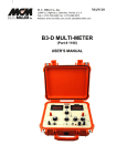
4.5 Connecting to the HART Network
The DevCom2000 PDA application communicates with the HART Field Devices through a HART compatible
communication interface (e.g., a "HART Modem"). Using this communication interface you will transmit real-time
HART data between DevCom2000 PDA and the connected HART compatible field device.
There are a wide variety of HART compatible interfaces. Please follow the manufacturer’s instruction for
connecting your interface to the PDA. This manual uses the HART modem manufactured by ProComSol, Ltd,
called the HM-BT-BAT. It uses the Bluetooth interface.
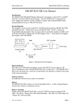
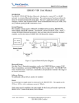
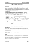
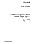
Turn the HM-BT-BAT on. It is assumed you have already performed the Bluetooth pairing procedure. See the
HM-BT-BAT documentation for details. Using the clips on the wires from the HART modem, connect to the
device across the 4-20ma signal. If a suitable load resistance is not available, a 250Ω resistor must be placed in
series with the device power supply.
Figure 1 Typical DevCom2000 PDA Hardware Setup
4.6 Uninstalling the DevCom2000 PDA Application
To uninstall the DevCom2000 PDA application, perform the following steps on the PC:
Step
Action
1
Click Start Programs ProComSol DevCom2000
PDA Uninstall DevCom2000 PDA
2
Or, Click Start Settings Control Panel Add/Remove
Programs
MAN-1017 07/15/08
Page 13
ProComSol, Ltd
DevCom2000 PDA User Manual
Step
Action
3
In the Add/Remove Programs dialog window, select the
DevCom2000 PDA program that you want to uninstall.
4
Click Remove.
5
Click OK to confirm the removing of the selected application.
MAN-1017 07/15/08
Page 14
ProComSol, Ltd
DevCom2000 PDA User Manual
5 USING DEVCOM2000 PDA
5.1 Starting DevCom2000 PDA
The HART compatible field device must be connected to a PDA running DevCom2000 PDA to configure or
calibrate the field device, or to view the field device's data. Make sure to establish the physical connection between
the field device and the DevCom2000 PDA computer. With the physical connection established, launch
DevCom2000 PDA by clicking the DevCom2000 PDA icon on your program screen. You can also start the
application by going to your PDA's Start Menu and selecting Start DevCom2000 PDA.
Step
Action
1
Start the DevCom2000 PDA Application. The following
application window is displayed:
DevCom2000 PDA will then automatically identify the field
device and open a communication channel to (i.e., a connection
with) the field device.
2
MAN-1017 07/15/08
Setting Preferences Device Preferences
If communications cannot be established, you may need to
change the communication settings using the Preferences dialog
box.
The serial port box will show the available com ports. Select the
one your HART modem is using. You may also change the
polling options for the computer. If you do not know the poll
address of the device you are trying to communicate with, use
the default address 0 setting.
Page 15
ProComSol, Ltd
DevCom2000 PDA User Manual
Step
Action
3
When the device is connected to DevCom2000 PDA, the
browser window appears with online (i.e. root menu) selected.
The top pane of the window shows the menu structure and the
bottom pane of the window displays corresponding parameters
of the menu selected.
The DevCom2000 PDA screens shown in this document are
only an example of what you may see when connected to your
field device. What you see is actually controlled by the DD and
the device. The menus, data, status and configurations displayed
MAN-1017 07/15/08
Page 16
ProComSol, Ltd
DevCom2000 PDA User Manual
Step
Action
are specified by the field device's manufacturer in the DD itself.
4
Select the required menu to configure or review the field
device's data.
5.2 Getting Familiarized with DevCom2000 PDA Explorer
5.2.1 Using the Menu Bar Menus
DevCom2000 PDA Explorer provides visual representation and structure of the application window.
Menu
Explanation
The Device Menu offers the following
sub-menu options:
New Device - Connect to a new device or
reconnect to the same device.
Preferences – Brings up the Preferences
dialog box.
Document Device – Brings up the
Document Device dialog box.
Exit - Exit DevCom2000 PDA.
The View Menu offers the following submenu options:
Toolbar - Hide or show the Tool Bar.
Status Bar - Hide or show the Status Bar.
Device Condition – View detailed device
status.
Available DDs – Shows what DDs are
available to DevCom2000 PDA
The Help menu offers the following submenu options:
DevCom2000 PDA Help – Brings up
Help information for the DevCom2000
PDA application.
Device Help – Brings up help information
for the connected device (if available).
About DevCom2000 PDA – Shows
copyright information, support
information, and application Serial
Number.
MAN-1017 07/15/08
Page 17
ProComSol, Ltd
DevCom2000 PDA User Manual
5.2.2 Using the Pop-up Menus
When you tap and hold a menu item, a Pop-up menu will appear with different functionality depending on what
menu item type was selected. A summary:
Menu
Explanation
The Menu Pop-up Menu offers the
following sub-menu options:
Open – Opens the selected menu.
Help – Brings up help information on the
selected menu.
Device Details – Brings DD information
for the connected device. Only works on
the Online menu.
The Variable Pop-up Menu offers the
following sub-menu options:
Edit – Brings up the Edit menu for the
selected variable.
Help - Brings up help information on the
selected variable.
Display Value – Shows the selected
variable on the full screen with scroll bars.
This is so the entire variable can be seen
without abbreviations.
The Method Pop-up Menu offers the
following sub-menu options:
Execute – Starts the selected Method in a
new window.
Help – Brings up help information for the
selected Method.
5.2.3 Using the Toolbar
When you start the application, by default, the toolbar buttons appears on the main window. If it fails to display,
click View Toolbar option from the menu bar to bring up the toolbar.
Following are the buttons available in the DevCom2000 PDA application toolbar to perform the necessary tasks:
Button
Description
Corresponding Menu Option
Connect to a new device
Device New Device
Send parameter changes to the
device
MAN-1017 07/15/08
Page 18
ProComSol, Ltd
Button
DevCom2000 PDA User Manual
Description
Corresponding Menu Option
Cancel parameter changes
View more status on Device
and Communication
(Command 48 status)
View Device Condition
Shows About screen
Help About
5.2.4 Familiarizing with Icons
DevCom2000 PDA application uses different icons to represent different elements of the application. Following
table lists the icons and their meanings:
Icon
Meaning
Indicates a menu or submenu in the navigation tree
Indicates a currently selected menu or submenu in the
navigation tree
Online menu icon. The actual DD menu comes under this.
Indicates a “Variable” item
Indicates a “Method” (Standard Operating Procedure) item
Indicates an “Edit Display” item
MAN-1017 07/15/08
Page 19
ProComSol, Ltd
DevCom2000 PDA User Manual
6 FUNCTIONS AND BASIC OPERATIONS
6.1 Overview
DevCom2000 PDA allows the user to monitor and configure a single device at a time in the field. Each device is
associated with the DD when the device information is present. A DD may contain any of the following
parameters/elements:
Variable
A variable is defined as the data contained in the device (e.g. Device Firmware Version). There are two types of
variables:
Editable Variable – It allows the operator to modify the value and download it to the device.
Non-Editable Variable – It is a read-only data from the device.
Edit Display
This option is used to view a group of parameters. You can also modify a single parameter from this group, based
on which other parameters of the device get altered.
For example, if the Engineering Unit of the device is modified, the corresponding Low Limits and High Limits
change as per the Engineering Unit set.
Method / Standard Operating Procedure (SOP)
This option helps to perform various tests on the device for instance, Self Test and Loop Test. A Method or SOP is
a series of steps that are executed in a sequence results in the completion of some device related tasks. When a
method gets invoked, it gives various warning messages and options to the user, by which the user can thoroughly
test the device. If a test is aborted by operator command at any stage of the sequence, the method invokes
additional steps to bring the device back to its original state before the test.
6.2 Viewing Device Configuration (typical, actual view may change based on DD)
To view the configuration of the device that is connected to DevCom2000 PDA, perform the following steps:
Step
Action
1
Ensure that the application is running and communications have
been established:
MAN-1017 07/15/08
Page 20
ProComSol, Ltd
Step
DevCom2000 PDA User Manual
Action
The top pane of the window shows the menu structure and the
bottom pane of the window displays corresponding parameters
of the menu selected.
The menus are displayed depending on the type of device that is
being connected. These menus are displayed based on the DD
file of the particular device.
If no DD is available for the device the DevCom2000 PDA will
select the standard DD. This should provide limited
functionality for the device. NOTE: If a parameter is updated
that is not supported by the device you will receive an error.
2
MAN-1017 07/15/08
Expand the menu by clicking the “+” sign and double-click to
view the device parameters. Below is an example of an
expanded menu:
Page 21
ProComSol, Ltd
DevCom2000 PDA User Manual
Step
Action
3
Select the menu and view the associated parameters to view the
device information.
6.3 Configuring Device Information
6.3.1 Overview
DevCom2000 PDA allows you to view and configure the field device parameters based on the device description.
However, the device vendor defines most of the parameters at the factory. These parameters become read only for
the users and the user cannot modify the values. The related variables are grouped under various menus of different
levels as defined in the DD file. Expand or collapse the tree view using the “+” or “-“sign to access the device
configuration parameters.
Following table describes the details about the device configuration:
Step
Action
1
Ensure that the application is running and communications have
been established:
MAN-1017 07/15/08
Page 22
ProComSol, Ltd
Step
DevCom2000 PDA User Manual
Action
The top pane of the window shows the menu structure and the
bottom pane of the window displays corresponding parameters
of the menu selected.
2
Expand the menu by clicking the “+” sign and double-click to
view the device parameters.
3
There are three types of variables: dynamic, read/write and read
only. The parameters that are grayed out indicate that these are
dynamic variables (variables that get updated online by the
device) or read only variables.
Following points describe how the device parameters represents
their status when connected to DevCom2000 PDA:
Bold Font: Modifiable Values
Normal Font: Menu Item
Gray Font: Dynamic or Read Only Variables
4
Select the parameter and configure the values, as required.
5
The subsequent topics explain how to configure device
parameters.
MAN-1017 07/15/08
Page 23
ProComSol, Ltd
DevCom2000 PDA User Manual
6.3.2 Variable
To edit the parameter variables of the connected device, perform the following steps:
Step
Action
1
Ensure that the application is running and communications have
been established:
Expand the menu by clicking the “+” sign and double-click to
view the device parameters.
2
MAN-1017 07/15/08
Select the menu where the editable parameter is present as
shown below:
Page 24
ProComSol, Ltd
DevCom2000 PDA User Manual
Step
Action
3
Tap and hold the variable to edit it. A pop-up menu will appear
on the screen:
4
Select “Edit”. The following dialog box appears on the screen:
MAN-1017 07/15/08
Page 25
ProComSol, Ltd
DevCom2000 PDA User Manual
Step
Action
5
Tap the Keyboard icon to bring up a keyboard for data entry.
The screen will now look like this:
Note that there are several ways to enter data using the PDA.
See Appendix B for more options.
6
Make the changes to the parameter value, as required.
7
Click Set to accept the changed value. The change gets reflected
as shown:
MAN-1017 07/15/08
Page 26
ProComSol, Ltd
Step
Action
8
Click on the Send icon
DevCom2000 PDA User Manual
to commit the changes to the device.
6.3.3 Edit Display
The Edit Display is a variation on the Variable edit. An additional window helps the user view a group of
parameters based on the DD. You can also modify a single parameter from this group. Parameters linked to the
edited field will be updated automatically
To view and configure these variables, perform the following steps:
Step
Action
1
Ensure that the application is running and communications have
been established
MAN-1017 07/15/08
Page 27
ProComSol, Ltd
Step
DevCom2000 PDA User Manual
Action
Expand the menu by clicking the “+” sign and double-click to
view the device parameters.
2
Double click the parameter you wish to edit. The following
dialog box appears on the screen:
3
Double click the parameter you wish to edit from within the Edit
Display box. The following dialog box appears on the screen:
MAN-1017 07/15/08
Page 28
ProComSol, Ltd
DevCom2000 PDA User Manual
Step
Action
4
Make the change to the value, as required.
5
Click Set to accept the changes. Or press Cancel to cancel the
changes.
6
Click OK to close the Edit Display dialog box.
7
Click on the Send icon
to commit the changes to the device.
6.3.4 Executing Methods or Standard Operating Procedures
Methods are defined in the DD file for the device that DevCom2000 PDA is connected to. You can select the
Method and execute it for calibrating the device, trouble shooting, etc. Method execution leads you through a
number of steps, like in a wizard.
A Few examples of methods include,
Setting high and low range calibration points
Calibration of the device
Run the advanced diagnostic test procedure
Execute tests to gather information on device operation.
To execute a Method, perform the following steps:
Step
Action
1
Ensure that the application is running and communications have
been established:
MAN-1017 07/15/08
Page 29
ProComSol, Ltd
Step
DevCom2000 PDA User Manual
Action
Expand the menu by clicking the “+” sign and double-click to
view the device parameters.
2
Select the menu where the method is present and tap and hold to
bring up the Method pop-up menu:
3
Select Execute to start the Method. Below is an example of a
Method screen:
MAN-1017 07/15/08
Page 30
ProComSol, Ltd
DevCom2000 PDA User Manual
Step
Action
4
Click OK to move to the next dialog in the Method sequence.
5
Or, click Abort to cancel the Method execution.
6
Click Help to get specific help for that step of the Method. This
Help information is provided by the device DD.
6.4 Calibrating HART Field Devices
Calibration of field devices and loop test are achieved by executing the Methods or Standard Operating Procedures
that are specific to device. Methods are defined based on the test parameters specific to the device, providing
information for the calibration of that device.
See the previous section for Method execution.
6.5 Viewing the Device and Communication Status
DevCom2000 PDA provides the user with the ability to monitor the device specific status of the device and the
communication network.
When there is error communicating with the device, it is recognized and indicated to the user. The user can view
more details of such errors, using the View Device Condition from the main window.
To view the device and communication status, perform the following steps:
Step
Action
1
Ensure that the application is running and communications have
MAN-1017 07/15/08
Page 31
ProComSol, Ltd
Step
DevCom2000 PDA User Manual
Action
been established:
Expand the menu by clicking the “+” sign and double-click to
view the device parameters.
2
Select View Device Condition from the main window or
choose the status icon
from the toolbar. Following window is
displayed:
The Device Status tab option shows the status of the device and
the communication network. The individual status is indicated
by green and red LEDs.
MAN-1017 07/15/08
Page 32
ProComSol, Ltd
DevCom2000 PDA User Manual
Step
Action
3
Additional tabs may be available depending on the DD. Tap the
arrow buttons to move amongst the tabs.
4
Click X to close the Status window.
6.6 Saving Device Configuration To Memory
HART Device configurations can be saved to memory as a text file to document the device. Fields are delimited
with a comma so that the data can be imported into configuration management software packages.
To save device configurations to disk, perform the following steps:
Step
Action
1
Ensure that the application is running and communications have
been established:
2
Select Device Document Device from the main window.
The Document Device Dialog Box is displayed:
MAN-1017 07/15/08
Page 33
ProComSol, Ltd
DevCom2000 PDA User Manual
Step
Action
3
The default directory is \HART Configs. The default file name
is Tag_Device ID. The filename can be changed by the user.
Use the “Browse” button to change directories and/or filenames
also.
4
Enter a Note in the Notes field if desired. Maximum of 255
characters.
5
Press the “Save Device Config” button to save device
configuration.
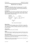
6.7 PC Interface to PDA
The Windows Explorer program is a convenient way to copy configuration files back to the PC for archiving and
storage. The PDA looks like a disk to the Windows file system. Below is an example screen shot:
MAN-1017 07/15/08
Page 34
ProComSol, Ltd
DevCom2000 PDA User Manual
The default location for the saved configuration files is the directory “\My Documents\HART Configs”. Simply
highlight the desired files and copy to your PC. Once on the PC, they can be viewed or imported to many different
software packages.
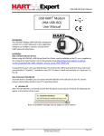
6.8 DD Library Updates
When the DD library update is installed on the PC, it is placed in the “C:\HCF\DDL\Library” directory. Simply
highlight this directory on the PC and drag and drop to the “SD Card” directory on the PDA.
MAN-1017 07/15/08
Page 35
ProComSol, Ltd
DevCom2000 PDA User Manual
Appendix A
Troubleshooting Guide
Problem:
Will not communicate
Hardware Check:
Verify the following:
1. Com port number on Preferences Dialog box matches HART interface hardware.
2. Loop power supply is on.
3. Loop resistance between 250 ohms and 1Kohms.
4. Loop current within HART limits.
5. If multi drop configuration, all transmitters in loop have unique addresses.
6. HART interface hardware connected across loop resistor or across transmitter terminals.
Problem:
Get the message “Error opening COMx”
Verify the following:
1. Com port number on Preferences Dialog box matches HART interface hardware.
2. HART interface hardware installed.
Problem:
The system cannot find the path specified error box
Try the following:
1. Verify that the DevCom2000 PDA SD Card is inserted into the SD slot of the PDA.
2. The name of the SD card is SD Card.
Problem:
Serial Number does not match Activation input boxes
Note the following:
1. The Program Serial Number entered during Install is different than Activation Codes entered during Activation.
2. Demo version of program still requires Program Serial Number.
3. Activation Codes required after 30 days of Demo program use.
MAN-1017 07/15/08
Page 36
ProComSol, Ltd
DevCom2000 PDA User Manual
Appendix B
PDA Data Input Guide
There are several different ways to enter data on a PDA. Tap the up arrow next to the Input Panel icon. The
following will appear:
Keyboard
Use the stylus to tap letters, numbers, and symbols on the on-screen keyboard to enter typed text directly onto the
screen.
1. From any application, tap the up arrow next to the Input Panel icon.
2. Tap Keyboard to display a keyboard on the screen. Note: To see symbols, tap the 123 key.
3. Tap a letter, symbol, or number to enter information.
4. Tap OK.
Letter Recognizer
Use the stylus and Letter Recognizer to write letters, numbers, and symbols on the screen. Create words and
sentences by writing in uppercase (ABC), lowercase (abc), and symbols (123) as instructed here.
1. From any application, tap the up arrow next to the Input Panel icon.
2. Tap Letter Recognizer.
3. Write a letter or symbol between the dashed line and baseline.
- To display in uppercase, write a letter between the hatch marks labeled ABC.
- To display in lowercase, write a letter between the hatch marks labeled abc.
- Write a number or draw a symbol between the hatch marks labeled 123.
MAN-1017 07/15/08
Page 37
ProComSol, Ltd
DevCom2000 PDA User Manual
What you write will be converted to text.
Note: For the Letter Recognizer to work effectively, write characters between the dashed line and baseline.
- If you are writing a letter like “p,” write the top portion within the dashed line and baseline, and the tail portion
below the baseline.
- If you writing a letter like “b,” write the bottom portion within the dashed line and baseline, and the top portion
above the dashed line.
Note:To view help on using Letter Recognizer, open the program and tap the question mark next to the writing
area.
Transcriber
Use the stylus and Microsoft Transcriber to write words, letters, numbers, and symbols anywhere on the screen.
1. From any application, tap the up arrow next to the Input Panel icon.
2. Tap Transcriber to display the Transcriber Intro screen.
3. Tap OK.
4. Tap New at the bottom of the screen.
5. Begin writing on the screen. What you write will be converted to text.
Note: To “teach” Transcriber your style of writing, tap on the “a” icon at the bottom of the screen to display the
Letter Shapes screen and follow the instructions.
Block Recognizer
Write letters, numbers, and symbols using the stylus and Block Recognizer. Create words and sentences by writing
letters and numbers in specific areas.
1. From any application, tap the up arrow next to the Input Panel button.
2. Tap Block Recognizer.
3. Write a word, letter, or symbol between the hatch marks.
- To type text, write a letter between the hatch marks labeled “abc.”
- To type numbers or symbols, write a number or symbol between the hatch marks labeled “123.” What you write
will be converted to text.
MAN-1017 07/15/08
Page 38
ProComSol, Ltd
DevCom2000 PDA User Manual
Appendix C
Contact Information
ProComSol, Ltd
Process Communications Solutions
13000 Athens Ave
Suite 104G
Lakewood, OH 44107
USA
Phone: 216.221.1550
Fax: 216.221.1554
Email: [email protected]
[email protected]
Web: www.procomsol.com
MAN-1017 07/15/08
Page 39