1
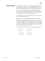
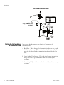
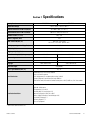
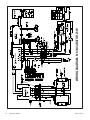
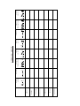
User Manual
Thermo Scientific Precision
Model 818 Incubator
Plant Growth Chamber - Microprocessor Controlled
Operating and Maintenance Manual 7013758 Rev. 0
Visit us online to register your warranty
www.thermoscientific.com/labwarranty
Preface
Covered in this manual:
Catalog Number (Model)
Volume
(L /cu. ft.)
Voltage
PR505755L (3759)
504/17.8
120V
PR505750L (3758)
504/17.8
230V
Manual Number 7013758
0
40096
4/3/15
Original - new cabinet size, technical data
ccs
Rev
ECR/ECN
Date
Description
By
Thermo Scientific
Plant Growth Chamber
i
Preface
CAUTION
Contains Parts and Assemblies
Susceptible to Damage by
Electrostatic Discharge (ESD)
Important Read this instruction manual. Failure to read, understand and follow the instructions in this manual
may result in damage to the unit, injury to operating personnel, and poor equipment performance. s
Caution All internal adjustments and maintenance must be performed by qualified service personnel. s
Warning If the growth chamber is not used in the manner specified in this operating manual, the protection
provided by the equipment design may be impaired. s
Warning Hot/warm surface(s) can occur. Depending on ambient termperature and settings, surface can become
warm (up to 60°C). s
Material in this manual is for information purposes only. The contents and the product it describes are subject
to change without notice. Thermo Fisher Scientific makes no representations or warranties with respect to this
manual. In no event shall Thermo be held liable for any damages, direct or incidental, arising out of or related to
the use of this manual.
©2015 Thermo Fisher Scientific. All rights reserved.
ii
Plant Growth Chamber
Thermo Scientific
Preface
Important operating and/or maintenance instructions. Read the accompanying text carefully.
Potential electrical hazards. Only qualified persons should perform procedures associated with this
symbol.
Equipment being maintained or serviced must be turned off and locked off to prevent possible injury.
Marking of electrical and electronic equipment, which applies to electrical and electronic equipment
falling under the Directive 2002/96/EC (WEEE) and the equipment that has been put on the market
after 13 August 2005.
This product is required to comply with the European Union’s Waste Electrical & Electronic
Equipment (WEEE) Directive 2002/96/EC. It is marked with the WEEE symbol. Thermo Fisher
Scientific has contracted with one or more recycling/disposal companies in each EU Member State
European Country, and this product should be disposed of or recycled through them. Further
information on Thermo’s compliance with this directive, the recyclers in your country and information
on Thermo Scientific products will be available at www.thermoscientific.com.
4
Always use the proper protective equipment (clothing, gloves, goggles, etc.)
4 Always dissipate extreme cold or heat and wear protective clothing.
4 Always follow good hygiene practices.
4 Each individual is responsible for his or her own safety.
Thermo Scientific
Plant Growth Chamber
iii
Preface
Do You Need Information or Assistance on
Thermo Scientific Products?
If you do, please contact us 8:00 a.m. to 6:00 p.m. (Eastern Time) at:
1-740-373-4763
1-800-438-4851
1-877-213-8051
http://www.thermoscientific.com
[email protected]
www.unitylabservices.com
Direct
Toll Free, U.S. and Canada
FAX
Internet Worldwide Web Home Page
Tech Support Email Address
Certified Service Web Page
Our Sales Support staff can provide information on pricing and give you quotations. We can
take your order and provide delivery information on major equipment items or make
arrangements to have your local sales representative contact you. Our products are listed on the
Internet and we can be contacted through our Internet home page.
Our Service Support staff can supply technical information about proper setup, operation or
troubleshooting of your equipment. We can fill your needs for spare or replacement parts or
provide you with on-site service. We can also provide you with a quotation on our Extended
Warranty for your Thermo Scientific products.
Whatever Thermo Scientific products you need or use, we will be happy to discuss your
applications. If you are experiencing technical problems, working together, we will help you
locate the problem and, chances are, correct it yourself...over the telephone without a service
call.
When more extensive service is necessary, we will assist you with direct factory trained
technicians or a qualified service organization for on-the-spot repair. If your service need is
covered by the warranty, we will arrange for the unit to be repaired at our expense and to your
satisfaction.
Regardless of your needs, our professional telephone technicians are available to assist you
Monday through Friday from 8:00 a.m. to 6:00 p.m. Eastern Time. Please contact us by
telephone or fax. If you wish to write, our mailing address is:
Thermo Fisher Scientific
401 Millcreek Road, Box 649
Marietta, OH 45750
International customers, please contact your local Thermo Scientific distributor.
iv
Plant Growth Chamber
Thermo Scientific
Preface
Warranty Notes
Information You Should Know Before Requesting Warranty Service
• Locate the model and serial numbers. A serial tag is located on the unit itself.
• For equipment service or maintenance, or with technical or special application inquiries, contact Technical
Services at 1-800-438-4851 or 1-740-373-4763 (USA and Canada). Outside the USA, contact your local
distributor.
Repairs NOT Covered Under Warranty
• Calibration of control parameters. Nominal calibrations are performed at the factory; typically ±1°C for
temperature, ±1% for gases, and ±5% for humidity. Our service personnel can provide precise calibrations as
a billable service at your location. Calibration after a warranty repair is covered under the warranty.
• Damage resulting from use of improper quality water, chemicals or cleaning agents detrimental to
equipment materials.
• Service calls for improper installation or operating instructions. Corrections to any of the following
are billable services:
1) electrical service connection
2) tubing connections
3) gas regulators
4) gas tanks
5) unit leveling
6) room ventilation
7) adverse ambient temperature fluctuations
8) any repair external to the unit
• Damage resulting from accident, alteration, misuse, abuse, fire, flood, acts of God, or improper
installation.
• Repairs to parts or systems resulting from unauthorized unit modifications.
• Any labor costs other than that specified during the parts and labor warranty period, which may
include additional warranty on CO2 sensors, blower motors, water jackets, etc.
Thermo Scientific
Plant Growth Chamber
v
Table of Contents
Thermo Scientific
Section 1
Introduction . . . . . . . . . . . . . . . . . . . . . . . . . . . . . . . . . . . . . . . . . . . . . . . . .1-1
Unpacking and Damage . . . . . . . . . . . . . . . . . . . . . . . . . . . . . . . . . . .1-1
Performance Data . . . . . . . . . . . . . . . . . . . . . . . . . . . . . . . . . . . . . . .1-2
General Information . . . . . . . . . . . . . . . . . . . . . . . . . . . . . . . . . . . . .1-2
Theory of Operation . . . . . . . . . . . . . . . . . . . . . . . . . . . . . . . . . . . .1-2
Explanation of Front Panel Controls . . . . . . . . . . . . . . . . . . . . . . . . .1-5
Explanation of Auxiliary Panel . . . . . . . . . . . . . . . . . . . . . . . . . . . .1-7
Instrumentation Port . . . . . . . . . . . . . . . . . . . . . . . . . . . . . . . . . . . . .1-8
Section 2
Installation . . . . . . . . . . . . . . . . . . . . . . . . . . . . . . . . . . . . . . . . . . . . . . . . . .2-1
Safety Precautions . . . . . . . . . . . . . . . . . . . . . . . . . . . . . . . . . . . . . . .2-2
Section 3
Operation and Calibration . . . . . . . . . . . . . . . . . . . . . . . . . . . . . . . . . . . . .3-1
To Lock the Keyboard . . . . . . . . . . . . . . . . . . . . . . . . . . . . . . . . . .3-6
To Unlock the Keyboard . . . . . . . . . . . . . . . . . . . . . . . . . . . . . . . .3-7
Adjusting the Intake and Exhaust Ports . . . . . . . . . . . . . . . . . . . . . .3-10
Section 4
Service . . . . . . . . . . . . . . . . . . . . . . . . . . . . . . . . . . . . . . . . . . . . . . . . . . . . . .4-1
Troubleshooting . . . . . . . . . . . . . . . . . . . . . . . . . . . . . . . . . . . . . . . . .4-1
Symptoms and Possible Causes . . . . . . . . . . . . . . . . . . . . . . . . . . .4-1
Possible Solutions . . . . . . . . . . . . . . . . . . . . . . . . . . . . . . . . . . . . . .4-3
Section 5
Maintenance . . . . . . . . . . . . . . . . . . . . . . . . . . . . . . . . . . . . . . . . . . . . . . . .5-1
General Cautions . . . . . . . . . . . . . . . . . . . . . . . . . . . . . . . . . . . . . . . .5-1
Section 6
Options . . . . . . . . . . . . . . . . . . . . . . . . . . . . . . . . . . . . . . . . . . . . . . . . . . . . . .6-1
RS232 . . . . . . . . . . . . . . . . . . . . . . . . . . . . . . . . . . . . . . . . . . . . . . . .6-1
Setting Up the Incubator for Communication . . . . . . . . . . . . . . . .6-2
Setting up the Computer for Communication . . . . . . . . . . . . . . . .6-5
Using the Communication . . . . . . . . . . . . . . . . . . . . . . . . . . . . . . .6-5
Section 7
Specifications . . . . . . . . . . . . . . . . . . . . . . . . . . . . . . . . . . . . . . . . . . . . . . .7-1
Section 8
Spare Parts . . . . . . . . . . . . . . . . . . . . . . . . . . . . . . . . . . . . . . . . . . . . . . . . . .8-1
Accessories . . . . . . . . . . . . . . . . . . . . . . . . . . . . . . . . . . . . . . . . . . . . .8-2
Plant Growth Chamber
vi
Section 1
Introduction
Your satisfaction and safety are important to Thermo and a complete
understanding of this unit is necessary to attain these objectives.
Warning As a routine laboratory precaution, always wear safety glasses
when working with this apparatus. s
This product is not intended, nor can it be used, as a sterile or patient
connected device. In addition, this apparatus is not designed for use in
Class I, II or III locations as defined by the National Electrical Code.
Unpacking and
Damage
Save all packing material until unit is put into service. This merchandise
was carefully packed and thoroughly inspected before leaving our factory.
Responsibility for safe delivery was assumed by the carrier upon acceptance
of the shipment; therefore, claims for loss or damage sustained in transit
must be made upon the carrier by the recipient as follows:
1. Visible Loss or Damage: Note any external evidence of loss or damage
on the freight bill, or express receipt, and have it signed by the carrier's
agent. Failure to adequately describe such external evidence of loss or
damage may result in the carrier's refusing to honor your damage
claim. The form required to file such claim will be supplied by the
carrier.
2. Concealed Loss or Damage: Concealed loss or damage means loss or
damage which does not become apparent until the merchandise has
been unpacked and inspected. Should either occur, make a written
request for inspection by carrier's agent within fifteen (15) days of the
delivery date; then file a claim with the carrier since the damage is the
carrier's responsibility.
If you follow the above instructions carefully, we will guarantee our full
support of your claim to be compensated for loss or concealed damage.
Note Do not - for any reason - return this unit without first obtaining
authorization. In any correspondence to Thermo, please supply the
nameplate data, including catalog number and serial number. s
Thermo Scientific
Plant Growth Chamber
1-1
Section 1
Introduction
General Information
The growth chamber has been commonly referred to as the standard
model 818.
The PR505750L can be converted for operation on 200V or 240V by
changing the input connections to the autotransformers (see wiring
diagram at the end of this manual).
The PR505750L/PR505755L Plant Growth Chamber has been designed
to provide the ultimate in temperature control. The user is assured of
dependable and precise performance through the use of microprocessor
technology in the temperature control circuitry. This growth chamber is
operable in the range of -10° to 50°C without illumination, and +10°C to
+50°C with illumination. These temperature ranges will meet a wide
variety of applications, such as BOD determination, general incubation,
as well as the preservation of critical materials.
Performance Data
*with door illumination switch on
Uniformity values:
Set
Temperature deviation
temperature from set value, spatial
(3 point measurement)
Uniformity values:
Temperature deviation
from set value, spatial
(27 point measurement
according to DIN 12880)
Temperature stability:
Maximum temperature
Energy
difference at chamber
consumption
center point (1 point
measurement)
Heat up time / Cool
down time from
ambient temperature
according to DIN
12880
Recovery time
after door opening according to
DIN 12880
-10°C
±0.8°C
±1.3°C
≤ ±0.25°C
≤ 0.3 kW
ca. 80 min
ca. 10 min
+10°C
±0.6°C / ±0.2°C
±1.9°C / ±1.3°C
≤ ±0.25°C
≤ 0.54 kW /
≤ 0.52 kW
ca. 54 min.*
ca. 4 min.
+20°C
±0.5°C / ±0.2°C
±1.8°C / ±0.9°C
≤ ±0.20°C
≤ 0.55 kW /
≤ 0.49 kW
N/A
N/A
+50°C
±0.25°C / ±0.15°C
±1.1°C / ±0.9°C
≤ ±0.15°C
≤ 0.56 kW /
≤ 0.51 kW
ca. 100 min. *
ca. 42 min. *
Note The above performance figures are based upon the following operating conditions:
- Ambient temperature of 22°C, ±3°C
- Line voltage 120V, ±5% (120V version) and 230V, ±5V (230V version)
The following test protocols have been used:
3 point measurement test: 1 thermocouple sensor in center of each shelf - 1 shelf top position, 1 shelf lowest
position, 1 shelf middle position
27 point measurement test: 9 x thermocouples on each shelf - 1 shelf top position, 1 shelf lowest position, 1
shelf middle position (based on DIN 12880)
1 point measurement test: 1 thermocouple at chamber center point (temporal temperature variation
characterized by the maximum temperature difference)
1-2
Plant Growth Chamber
Thermo Scientific
Section 1
Introduction
Theory of Operation
The refrigeration system, defrost heater, and air circulating fan are used in
conjunction with a microprocessor controlled proportioning circuit to
achieve sensitive temperature control. An RTD (Resistance Temperature
Detector) located in the airstream senses any temperature deviation from
the control point, and heat is provided proportionally to maintain the
desired temperature. Regardless of what temperature is being maintained,
the compressor operates continuously. This constant operation alleviates
component failures associated with cycle type operation.
The circulating fan provides even air distribution throughout the chamber
and ensures temperature uniformity.
The program mode of PR505750L/PR505755L plant growth chamber
allows the user to program into memory 2 sets of values for time, setpoint
temperature, and light condition per day for a full week. The following is
an example of a schedule and a pictorial describing the events during that
week. A blank schedule sheet is provided toward the end of the manual for
the user to copy, then document a schedule. It is strongly recommended to
do this before any programming is performed.
The growth chamber leaves the factory with a default schedule as follows:
Hr1
1am
1pm
Min1 00
Min2 00
Set1
Set2
20.0
LGT1 OFF
Thermo Scientific
Hr2
20.0
LGT2 OFF
Plant Growth Chamber
1-3
1-4
Plant Growth Chamber
2 AM
FRIDAY
1 AM
3AM
THURSDAY
SATURDAY
4 AM
3 AM
TUESDAY`
WEDNESDAY
2 AM
1 AM
MONDAY
SUNDAY
HOURS
AM/PM
00
00
00
00
00
00
00
MINUTES
20.0
10.0
50.0
10.0
20.0
30.0
20.0
SETPOINT
TEMPERATURE
ON
ON
OFF
ON
OFF
ON
OFF
LIGHT
ON/OFF
3 PM
4 PM
5 PM
6 PM
5 PM
4 PM
3 PM
HOURS
AM/PM
SAMPLE SCHEDULE SHEET
00
00
00
00
00
00
00
MINUTES
30.0
20.0
40.0
50.0
10.0
20.0
40.0
SETPOINT
TEMPERATURE
OFF
OFF
ON
ON
OFF
ON
ON
LIGHT
ON/OFF
Section 1
Introduction
Thermo Scientific
Section 1
Introduction
Explanation of Front
Panel Controls
1) AM/PM Lamps - These two green indicator lamps inform the user as
to the12-hour time period of the day.
2) Time Display - This four-digit display indicates the time of day. In the
program mode, this display shows what parameter is being
programmed.
3) Day-of-the-Week Lamps - These seven green indicators show what day
it is.
4) Mode Lamps - These two indicators inform the user whether the
growth chamber is in a continuous mode of operation, or a program
mode of operation (timed sequence).
5) Temperature Display - This four-digit display indicates the growth
chamber chamber temperature. Also, during programming, it displays
the value prompted by the time display.
6) Heater On Lamp - This lamp is illuminated when power is applied to
the heater.
7) High/Low Temperature Lamps - These lamps will illuminate if the
growth chamber's chamber temperature exceeds the high or low limit
temperatures.
8) Locked Lamp - This lamp will illuminate if the user has locked the
keyboard to avoid accidental changing of parameters.
4
2
3
7
1
5
6
19
17
18
9
16
15
13
11
14
Thermo Scientific
8
10
12
Plant Growth Chamber
1-5
Section 1
Installation and Start-Up
Explanation of Front
Panel Controls (cont.)
9) Light On/Off Lamps - These two lamps indicate the status of the
internal light (whether it is on or off) during operation.
10) Enter Key - This key is used after any setpoint selection is made to
enter the value into memory.
11) Program Key - When the program mode is selected with the SET key,
the PROGRAM key will prompt the user to enter program values
starting with SUNDAY.
A blank schedule sheet is provided toward the end of this manual so the
user can predetermine the weeks program. Use of the schedule sheet is
strongly recommended before any programming is started.
12) Set Key - This key has two functions. The first being to select the
continuous or program mode of operation. The second being to select
a setpoint temperature if the continuous mode of operation has been
selected.
13) Up/Down Arrow keys - These keys are used to increase or decrease a
desired value.
14) REPEAT KEY - This key is a time saver key. When in the program
mode, pressing this key will duplicate the program setting from the
current day to the other 6 days.
15) CAL KEY - This key is used to calibrate the growth chamber to a
certified/traceable thermometer.
16) Mute Key - This key is used to silence the internal audible alarm and
to also deactivate the external alarm device if one is being used.
17) Light Key - This key, in Continuous mode, will turn the internal light
on or off. In Program mode, this key is disabled. The internal light will
not be allowed to operate at a setpoint temperature below 10 degrees in
either the Continuous or Program mode.
18) Lock Key - This key is used to enable or disable the keyboard.
19) Clock Key - This key is used to select the day, hours, and minutes.
1-6
Plant Growth Chamber
Thermo Scientific
Section 1
Installation and Start-Up
Explanation of Auxiliary
Panel
On the left side of the growth chamber control panel there is an auxiliary
panel which has the items shown in the figure on the next page. They are
described as follows:
1) Fuse - This fuse is in line with the main power cord that comes into
the growth chamber. The rating of this fuse is printed above the fuse
holder. The physical size of this fuse is 5mm x 20mm.
2) Alarm Relay - This Alarm Relay output is provided to the user for the
purpose of remotely monitoring the growth chamber in case of a high
or low temperature alarm condition. This alarm relay will operate just
as the audible alarm would. The contact itself is an isolated form C
(normally open/normally closed) dry contact. This contact is to be
used for low voltage class 2 connections only. The contact rating is 24
volts, 1.25 amps resistive. Typical usages of the output are shown
below.
In this configuration, the light will illuminate whenever the unit goes into
an alarm condition, High or Low.
In this configuration, the light will go off in a high or low temperature
alarm condition.
Note Wiring must conform to all local electrical codes. s
Thermo Scientific
Plant Growth Chamber
1-7
Section 1
Installation and Start-Up
Explanation of Auxiliary
Panel (continued)
3) RS-232 Output (Optional Kit P/N 3166245) -This output is used for
two way communications between the growth chamber and a personal
computer. With the use of a communications/modem software
program, the user can record the temperature of the growth chamber at
their selected time periods and store it in a file for use with a
spreadsheet program. The user can also change the setpoint
temperature from their personal computer and periodically monitor the
actual temperature, setpoint temperature, and alarm status.
4) Recorder Output - This is a DC millivolt output which represents the
temperature of the growth chamber. The recommended main use of
this is with a chart recorder having an input impedance of at least 1M
ohm. The scaled temperature output
change is 10mV°C. When the growth
chamber is operating at a negative
temperature, the chart recorder output
is still positive. Use the chart at right
to relate temperature to output voltage.
When connecting a chart recorder to
the recorder output connector, it is
recommended to use a shielded cable
with the shield grounded at the chart
recorder and to keep the cable short as
possible.
Instrumentation Port
1-8
Plant Growth Chamber
Located on the rear side of the growth chamber is an instrumentation port
for the user to insert sensor wires, external meter leads, etc. into the
chamber. The rubber plug provided must always be used in this port to
insure the uniformity specifications. An extra plug is supplied for the user's
convenience. Be sure to seal any gaps around the wire(s) going through the
plug.
Thermo Scientific
Section 2
Installation
Use the proper lifting equipment when moving this unit. The shipping
weight of this unit is 340 lbs. (154 kg).
To ensure proper ventilation, allow 4" minimum clearance between the
rear, top, and sides of the growth chamber and adjacent walls. If two or
more growth chambers are positioned side by side, allow a minimum of 8"
between cabinets. Adjust the front leveling feet of the growth chamber so
that the front is higher than the rear. This will assist in door closing.
Choose a site free from rapidly changing ambient temperature conditions.
Caution The growth chamber should not be operated in an environment
where the ambient temperature exceeds 90°F, as the compressor thermooverload will be tripped and will result in a wide band control cycle of
approximately ±4°C. Such cycling should not be misinterpreted as a
malfunction of the electronic controls. s
Radiators, air-conditioning outlets, other ventilating system outlets, and
drafts can affect the operation of the growth chamber by a sudden inrush
of air that is at a temperature different than operating conditions.
Warning For personal safety, this apparatus must be properly grounded. s
Wall mount brackets are attached to the top rear of the cabinet. Remove
any packaging materials from the brackets. Rotate the brackets so they
point straight out from the back. Secure bracket in place with the included
hardware. Attach brackets to wall.
Figure 2-1. Brackets During Shipping
Figure 2-2. Brackets During Use
The power cord is the mains disconnect. Make sure the outlet and plug are
accessible at all times.
Thermo Scientific
Plant Growth Chamber
2-1
Section 2
Calibration
The power cord of this instrument is equipped with a three-prong
(grounding) plug which mates with a standard three-prong (grounding)
wall receptacle to minimize the possibility of electric shock hazard from
this apparatus. The customer should have the wall receptacle and circuit
checked by a qualified electrician to make sure the receptacle is properly
grounded.
Where a two-prong wall receptacle is encountered, it is the personal
responsibility and obligation of the user to have it replaced with a properly
grounded three-prong wall receptacle.
Warning Do not, under any circumstances, cut or remove third (ground)
prong from the power cord. Do not use a two-prong adapter plug. s
Determine the total amount of current presently being used by other
apparatus connected to the circuit that will be used for this unit.
It is critical that the added current demand and other equipment on the
circuit not exceed the rating of the fuse or circuit breaker in use.
Caution Be sure the power supply is the same voltage as specified on the
nameplate. s
When loading the growth chamber, a space of 1/2" must be allowed
between adjacent items in the chamber. This will allow maximum air
circulation, necessary for proper temperature uniformity. The uniformity
will be adversely affected if air circulation is obstructed.
Liquid containers should never be placed in the growth chamber without
covers. The evaporation of moisture within the chamber will only add frost
and hasten the need for defrosting. This chamber is not self-defrosting.
Excessive frost buildup on the evaporator coil located on the lower back
wall will also affect temperature uniformity.
Safety Precautions
1. Do not place any explosive,combustible, or flammable materials in the
chamber.
2. Do not place sealed containers in the chamber. Sealed containers, filled
with material, do not provide room for expansion and can develop
dangerous vapor pressure as the temperature increases.
3. Avoid spillage of liquids within the chamber.
4. Do not evaporate noxious fumes.
Caution Do not store containers filled with acidic or caustic solutions, as
vapors from these materials will attack the evaporator and void the
2-2
Plant Growth Chamber
Thermo Scientific
Section 3
Operation and Calibration
In the "Explanation of Controls" section, all of the control panel keys were
discussed. In this section, some of those keys will be discussed in greater
detail due to their more involved operation.
1. Clock Key - Pressing the CLOCK key will enable the user to select the
hours, minutes, and day. The clock will continue to function correctly
if the growth chamber's power has been removed.
The date, month, and year selection is performed in Configuration
mode and will be discussed later. The date, month, and year have been
preset at the factory. If required, see CALENDAR in this section.
A. Press the CLOCK key and the displays will show the following:
A number other than 10 might be shown in the right display. Also,
if no keys are pressed within 15 seconds, the displays will return to
their previous state.
Using either the up or down arrow keys, the user can select the
correct hour of the day. After the correct hour has been selected,
ENTER must be pressed and the displays will change to those
illustrated in Step B. If the hour was correct when the CLOCK
was pressed, press ENTER and the displays will change to those
shown in Step B.
B. The displays will be similar to those below. These are for the
minute selection.
Again, a number other than 21 will most likely appear. This
display also has a 15-second time-out, just as the hour display.
Also, the next two displays in Steps C and D will have a 15-second
time-out.
If the minutes are correct, press the ENTER key and the displays
will go to those in Step C.
If the minutes are incorrect, use the up or down arrow keys to
select the correct minutes and then press ENTER. The displays
will go to those shown in Step C.
Thermo Scientific
Plant Growth Chamber
3-1
Section 3
Operation and Calibration
C. The displays will be similar to those below. This is for AM/PM
selection.
If the AM/PM is correct as indicated by the AM/PM lamps, then
press ENTER and the displays will go to those in Step D.
If the AM/PM is incorrect, use the u or down arrow keys to select
the proper one and then press ENTER.
D. The displays will be similar to those below. These are for the day
selection.
If the day is correct, press ENTER and the growth chamber will
return to regular operation and the setting of the clock is complete.
If the day is incorrect, use the up or down arrow keys to select the
day. While using the up or down arrow keys, observe the seven
day-of-the-week lamps for selecting the correct day. After the
correct day has been selected, press ENTER and the growth
chamber will return to normal operation and the setting of the
clock is complete.
2. Set Key - Pressing this key will change the displays to one of the
combinations shown below.
At this time, the user can select the growth chamber to operate in the
PROGRAM mode or CONTINUOUS mode.
If CONT is displayed, and you wish to change to PROG, press the up
arrow key. The displays will return to their normal operation of
showing time and temperature. Also the continuous lamp will
extinguish and the PROGRAM lamp will illuminate. The growth
chamber will automatically determine the programmed set point
temperature and light status for the present time and day of the week.
3-2
Plant Growth Chamber
Thermo Scientific
Section 3
Operation and Calibration
If PROG is displayed and you wish to change to CONT, press the
down arrow key and the displays will change to the following:
Now the user can select the SETPOINT temperature to operate at by
means of the up or down arrow keys, then pressing the ENTER key.
Note If the user selects the CONTINUOUS mode of operation after
being in Program mode, the setpoint and light condition will remain the
same while the growth chamber was in Program mode. s
3. PROGRAM KEY - Before reading about this key, please take some
time to study the sample schedule sheet provided on page 1-4.
For each day, there are eight items which must be programmed and
are as follows:
Hour 1 (AM or PM)
Minute 1
Setpoint Temperature 1
Light On/Light Off 1
Hour 2 (AM or PM)
Minute 2
Setpoint Temperature 2
Light On/Light Off 2
When programming, it is important to keep in mind that "Hour 1"
must always be before "Hour 2". Also keep in mind that AM is before
PM.
Another important note about the operation of the program mode is
that, if the present time is before "Hour 1" of any day, the operation
of the growth chamber will be that of "Hour 2" of the previous day.
Thermo Scientific
Plant Growth Chamber
3-3
Section 3
Operation and Calibration
PROGRAM mode of the 3758/3759 Plant Growth Chamber allows
the user to program in two sets of time, setpoint temperature, and light
conditions for each day of the week. This is started by selecting
PROGRAM mode pressing the SET key, then pressing the
PROGRAM key. The displays and the indicator lamps will change to
the following:
Use the up or down arrow keys to select your choice for the first hour
for Sunday.
There is no separate selection for AM/PM here as there is for setting
the clock, but note the AM/PM lamps.
After your selection is displayed, press the ENTER key and the displays
will change to the following:
Use the up or down arrow keys to select your choice for the first
minutes for Sunday. After your selection is displayed, press the
ENTER key and the displays will change to the following:
Use the up or down arrow keys to select your choice for the setpoint
you want the growth chamber to switch to at your first hour and
minute you have chosen. After your selection is displayed, press the
ENTER key and the displays will change to the following:
3-4
Plant Growth Chamber
Thermo Scientific
Section 3
Operation and Calibration
Use the up or down arrow keys to select if you want the internal door
lamps to be on or off at your first hour and minute selection. After
your selection is displayed, press the ENTER key and the displays will
change to the following:
Use the up or down arrow keys to select your choice for the second
hour for Sunday. Note the AM/PM lamps. After your selection is
displayed, press the ENTER key and the displays will change to the
following:
Use the up or down arrow keys to select your choice for the second
minutes for Sunday. After your selection is displayed, press the
ENTER key and the displays will change to the following:
Use the up or down arrow keys to select your choice for the setpoint
you want the growth chamber to switch to a your second hour and
minute you have chosen. After your selection is displayed, press the
ENTER key and the displays will change to the following:
Use the up or down arrow keys to select if you want the internal door
lamps to be on or off at your second hour and minute selection. After
your selection is displayed, press the ENTER key and the displays will
change to the following:
At this point, the whole sequence starts over except that it is for
Monday instead of Sunday.
If any of the selections are already what you desire, for any day, just
press the ENTER key to advance to the next parameter.
While in PROGRAM mode, if you do not press any keys for 10
seconds, the growth chamber will automatically return to the normal
operation mode.
Thermo Scientific
Plant Growth Chamber
3-5
Section 3
Operation and Calibration
4. Repeat Key - This is a convenience key for the user. If the user desires
to program each day with the same times, temperature set points, and
light conditions, then the use of this key is very helpful.
A. Select PROGRAM mode of the growth chamber by using the SET
key.
B. Press the PROGRAM key, then go to the present day by means of
the ENTER key.
C. Select and enter all eight of the days' parameters desired.
D. After the last parameter (LGT2)is entered for the present day, the
day of the week lamps will indicate the next day. At this time,
press the REPEAT key. After about a half second, the displays will
return to normal operation.
E. All of the days program schedules will be the same as the present
day.
5. Lock Key - The keyboard may be locked to prevent inadvertent
changes to previously stored values.
To Lock the Keyboard
A. Press the LOCK key and the displays will show the following:
B. Using the up or down arrow keys, select a numerical password of your
choice.
C. Press the ENTER key. The LOCKED lamp will light and the displays
will return to their normal operation.
Your numerical password is stored and the keyboard is now locked.
Note Record your password in a safe place. s
The locked keys are CLOCK, LIGHT, up or down arrow keys,
REPEAT, and PROGRAM.
3-6
Plant Growth Chamber
Thermo Scientific
Section 3
Operation and Calibration
To Unlock the Keyboard
SET and CAL will show the present values, but if changes are
attempted, they will be locked out.
A. Press the LOCK key and the displays will show the following:
B. Using the up or down arrow keys, select the numerical password that
was chosen to lock the keyboard.
C. Press ENTER. The LOCKED lamp will go out and the displays will
return to their normal operation. The keyboard is unlocked at this
point.
Note If you have forgotten or lost your password, enter the number 257 to
unlock the keyboard. s
6. CALIBRATE KEY - The growth chamber is calibrated at the factory
for use over a wide range of temperatures. Due to the slight nonlinearization in the control system, it may be necessary to make the
display match a calibrated thermometer's reading, even though the
difference might be only a few tenth's of a degree.
The CALIBRATE key should be used ONLY to match a stable growth
chamber's actual temperature to the calibrated thermometer.
Place a calibrated thermometer (or the probe of one) at the center of
the third shelf of the growth chamber. Select the SETPOINT you
wish to run the unit at. Allow the unit to run for at least an hour after
it reaches the setpoint, before the calibration is performed.
Note If possible, place the thermometer into a liquid for stability. s
To perform calibration, press the CAL key. The displays will show the
following:
Note The temperature displayed will be current operation. s
Then press either the up or down arrow keys to make the display
match the noted thermometer reading. After the satisfied display is
achieved, press the ENTER key. The temperature display will then
return to showing the newly calibrated actual temperature. The TIME
display will return to displaying the time of day.
Thermo Scientific
Plant Growth Chamber
3-7
Section 3
Operation and Calibration
7. ALARMS - The growth chamber has high and low alarms. There are
settable delay timers and alarm band associated with these alarms. The
high and low timers provide a delay before either alarm will go off if
the chamber temperature has deviated from the setpoint temperature
by the amount set in the alarm band. These time delays and alarm
band are used in the control to distinguish between door openings and
real alarms. The following is an example of this:
The growth chamber is controlling at 40.0°C and the low delay timer
is set for 2 minutes and the alarm band is set for 1°. Now the door is
opened. Most likely, the temperature will begin to drop.
If the door is not closed and the control senses a temperature of 39°C
or less after 2 minutes, the low alarm temperature will go off along
with the compressor. This is not a real alarm failure. If the door is left
open long enough for this to occur, then the door must be closed
sooner so the growth chamber can recover in time. Alternately, the
delay times can be set for a longer period of time, or the alarm band
can be increased.
To adjust the delay timers and the alarm band, follow these instructions:
A. Press and hold the up or down arrow keys and then press the
ENTER key and the displays will change to the following:
Use the up arrow key to select 01 and then press ENTER. The
displays will change to the following:
A number other than 01 might be shown. This is the delay time
setting, in minutes, for the high alarm. Use the up or down arrow
keys to select your time value and press ENTER and the displays
will change to the following:
3-8
Plant Growth Chamber
Thermo Scientific
Section 3
Operation and Calibration
This is the delay time setting for the low alarm. A difference
between the high alarm and low alarm delay that should be noted
at this point is that when you select a value for the high alarm
delay and then turn power off, that value will appear again when
power is turned on again. The low alarm delay however will always
be 20 minutes when power is turned on. The reason for this, if the
delay is set for too short of a time and the compressor goes off, it
will be approximately 10 minutes before the compressor turns back
on. This is due to an internal time delay within the compressor.
The user can change this 20 minutes to a value desired, but when
power is turned off and on again, it will reset to 20 minutes again.
Use the up or down arrow keys to select your time value and press
ENTER.
The displays will change to the following:
This is the value for the alarm band, the amount of temperature
deviation allowed before either the high or low delay timers are
started. Use the up or down arrow keys to select your value and
then press ENTER and the displays will return to their normal
operation.
8. CALENDAR - The clock key allows the hours, minutes, and day of
the internal clock to be set. To set the internal clock, select
Configuration mode 2. To set the date, month, and year, follow these
instructions:
A. Press and hold the up or down arrow keys and then press the
ENTER key and the displays will change to the following:
Use the key to select 02 and then press ENTER. The displays will
change to the following:
A number other than 01 might be shown.
This is the day of the month selection. Use the up or down arrow
keys to select the correct date and then press ENTER and the
displays will change to the following:
Thermo Scientific
Plant Growth Chamber
3-9
Section 3
Operation and Calibration
Use the up or down arrow keys to select the correct month and
then press ENTER and the displays will change to the following:
Use the up or down arrow keys to select the correct year and then
press ENTER. The calendar is set and the growth chamber will
return to normal operation at this point.
Adjusting the Intake
and Exhaust Ports
3-10
Plant Growth Chamber
The exhaust port is the top port on the door. Open it slightly by turning it
counterclockwise to permit exhausting of chamber air. The intake port is
the bottom port on the door. Open the intake port by turning it
counterclockwise to permit an air exchange in the chamber.
Thermo Scientific
Section 3
Preventive Maintenance
PREVENTIVE MAINTENANCE
Incubators
Your equipment has been thoroughly tested and calibrated before shipment. Regular preventive maintenance is important to keep your
VOJUfunctioning properly. The operator should perform routine cleaning and maintenance on a regular basis. For maximum performance
BOEefficiency, it is recommended the unit be checked and calibrated periodically by a qualified service technician.
The following is a condensed list of preventive maintenance requirements. See the specified section of the operating manual for further
details.
We have qualified service technicians, using NIST traceable instruments, available in many areas. For more information on Preventive
Maintenance or Extended Warranties, please contact us at the number listed below.
Cleaning and calibration adjustment intervals are dependent upon use, environmental conditions and accuracy required.
Tips for all incubators:
Do NOT use bleach or any disinfectant that has high chloros
Use sterile, distilled or demineralized water.
Do not use powdered gloves for tissue cultures.
401 Millcreek Road, Box 649 • Marietta, Ohio 45750 USA • 740-373-4763
USA and Canada 800-438-4851 • Telefax: 740-373-4189 • http://[email protected]
Preventive Maintenance for Model 815 Incubators
Refer to
Manual
Section
Action
Daily
Weekly
Yearly
3
Check temperature display versus setpoints, w/ independent instrument
--
Inspect door latch, hinges and door gasket seal.
3
Verify and document temp calibration, as applicable. See Calibration section.
5
Perform a complete decontamination procedure. Wipe down interior, shelves
and side panels with disinfectant. Rinse everything well with sterile distilled
water.
Thermo Scientific
Between experiments
More frequent decontamination
may be required, depending on use
and environmental conditions
Plant Growth Chamber
3-11
Section 4
Service
Warning Service should be performed only by qualified service personnel.
Exercise care as line voltage is present in the control compartment. s
If refrigeration service is required, after review of the Troubleshooting
Section, contact Technical Services.
In any communication with Thermo, include the model and serial
numbers from both nameplates.
Troubleshooting
Problems encountered with any constant temperature chamber will most
frequently be related to temperature control. Before proceeding with
detailed troubleshooting, be certain that the Low Limit and High Limit
controls are adjusted properly. If the limit controls are set too close or
beyond the operating temperature, the growth chamber may be
consistently going into alarm. This will result in erratic temperature
control. First, the symptoms and possible causes will be listed for quick
reference. Possible solutions will be suggested later.
Warning Hazardous high voltage conditions exist inside the control panel.
unplug line cord and turn "off" line switch before removing the cover.
only qualified electrical instrument personnel are authorized to perform
troubleshooting and/or servicing. s
Symptoms and Possible
Causes
Freeze-up or gradual drop in chamber temperature:
No air circulation in chamber; inoperative fan (see Solution 1)
Heater (see Solution 2)
Power Supply PCB Assembly (see Solution 3)
RTD Temperature Probe (see Solution 3, Step D and/or Solution 4).
Side walls are getting warm:
Depending on ambient temperature and the specific settings, the side
walls may get warm to the touch - up to 60°C (140°F) .
This is not a malfunction. This is normal due to the location of the condenser heat exchanger of the cooling system. Note that it has no impact
on the specified performance of the unit.
Thermo Scientific
Plant Growth Chamber
4-1
Section 4
Service
Symptoms and Possible
Causes (continued)
Temperature variations at set point (poor control):
Excessive ambient temperature variations (see Solution 10)
Compressor Relay failure (see Solution 12)
No air circulation in chamber; inoperative fan (see Solution 1)
RTD Temperature Probe Location (see Solution 5)
Ice buildup on evaporator coils (see paragraph on "Defrosting")
RTD Temperature probe (see Solution 3, Step D and/or Solution 4).
Power Supply PCB Assembly (see Solution 3)
Does not reach a high set point temperature:
No air circulation in chamber; inoperative fan (see Solution 1)
Low line voltage, less than 110V (see Solution 9)
RTD Temperature Probe (see Solution 3, Step D and/or Solution 4).
Power Supply PCB Assembly (see Solution 3)
Overcharged compressor (see Solution 11)
Differences between Temperature Set and Digital Temperature Readout:
(see performance figures, page 3)
RTD Temperature Probe (see Solution 3, Step D and/or Solution 4).
Malfunctioning Power Supply PCB assembly (see Solution 3)
Takes an extremely long time to reach high temperature set point:
No air circulation in chamber; inoperative fan (see Solution 1)
Low line voltage, less than 110V (see Solution 9)
Power Supply PCB assembly (see Solution 3)
Overcharged Compressor (see Solution 11)
UUUU
Display indicates
or UUUU
Malfunctioning RTD Temperature Probe (Solution 4)
4-2
Plant Growth Chamber
Thermo Scientific
Section 4
Service
Possible Solutions
1. Inoperative Fan:
Open the door. Place your hand near the grille at the top rear of the
chamber and check for air circulation. If there is no air circulation, the
fan motor is malfunctioning. Contact Technical Services.
2. Burned-out heater:
To check this, the control panel cover must be removed.
Warning Hazardous high voltage conditions exist inside control panel.
Turn ‘OFF’ line switch on front panel and disconnect line cord. s
Remove all screws that fasten the cover. Locate nylon connector J1 on
the Limit/Alarm PCB Assembly. Depress both ears on the plug
housing and gently pull out the connector.
With an Ohmmeter, measure the resistance between TB1-4 (Orange
wire) and TB1-6 (Red wire).
The proper heater resistance is 24 ohms. If heater resistance is correct,
then measure between one heater lead (RED or ORANGE) and
growth chamber ground, it must be infinity (Open). If the heater
resistance check indicates an open circuit, it may or may not be open.
In series with the heater is a thermal overload switch. It might be that
this thermal overload is open and not the heater. To check the heater
and thermal switch directly, the shelfs of the growth chamber and the
back wall cover must be removed. Unplug heater and measure it’s
resistance. If the resistance is correct, check resistance between heater
terminal and the heater sheath. It must be an open circuit. If the
heater is good, then check the thermal overload switch. At room
temperature it should be closed (0 ohms). This switch should only
open at 80°C, then close at 65°C. If the heater and thermal switch are
good, then the problem is directed towards the heater wires in the
harness. If heater is defective, contact Technical Services.
3. Malfunctioning Power Supply PCB assembly:
The Power Supply PCB Assembly has the triac (solid state AC voltage
switch) on it which supplies the power to heater. This triac is "told" to
operate, when need be, by the microprocessor.
Thermo Scientific
Plant Growth Chamber
4-3
Section 4
Service
Possible Solutions
(continued)
There is another device known as an Optoisolator which serves as the
high/low voltage isolator between the triac and the microprocessor.
When the growth chamber starts experiencing temperature problems
and/or variations, due to known controller malfunctions, these two
components become prime suspects. The reason being they are under
higher operating stress than other components.
If the growth chamber starts experiencing temperature problems such as no
heat, constant heat, or "creeping" upward heat, then follow the
troubleshooting instructions below. These instructions require the use of a
voltmeter being able to measure DC and AC voltages and preferably a
digital voltmeter.
Warning The following troubleshooting instructions require that power be
on. Only qualified service personnel should perform these procedures. s
A) Remove the control cover and familiarize yourself with the power
supply assembly #3176818. Locate the Triac (Q2), the Opto-isolator
(U1), resistor (R4). Also locate the test point #2 (TP2). The first
measurements will be DC voltage measurement, so a DC scale of at
least 10 volts should be selected. Connect the negative lead to TP2.
This is DC ground. Also locate the terminal block (TB1).
B) This first section will be to verify the heater command is correct from
the microprocessor, through the optoisolator, and through the triac
when the growth chamber is NOT requesting heat. The steps in this
section must be followed in succession.
1. Select a setpoint temperature at least 10° below what the actual
temperature is. The growth chamber should not be requesting heat
as indicated by the "Heater On" indicator lamp on the front panel.
It should not be on continuously, or even flashing.
2. Measure the voltage at U1-Pin 2 with respect to TP2. It should be
no less than 4 volts DC.
3. Measure the DC voltage across R4, since the growth chamber is
not requesting heat, there should be no current flowing through
this resistor, making the voltage drop equal to 0 volts.
4. If the last two steps are not as stated, then most likely the CPU
board is bad and should be replaced.
5. Switch the voltmeter to an "AC Volts" scale capable of reading 120
volts.
4-4
Plant Growth Chamber
Thermo Scientific
Section 4
Service
Possible Solutions
(continued)
6. Measure the voltage between U1-Pin 4 and U1-Pin 6. It should be
line voltage; 110 VAC to 120 VAC.
7. If it is not, most likely the Optoisolator is bad and the power
supply board should be replaced.
8. Measure the voltage TB1-4 (Orange wire) and TB1-6 (Red wire).
It should be approximately 0 VAC.
9. If it is not, then most likely the triac is bad, and the power supply
board should be replaced.
C) This next section will be to verify the heater command is correct from
the microprocessor, through the optoisolator, and through the triac
when the growth chamber IS requesting heat. The steps in this section
must be followed in succession.
1. Select a setpoint temperature at least 10° above what the actual
temperature is. The growth chamber should be requesting heat as
indicated by the "Heater On" indicator lamp on the front panel. It
should be on continuously, not flashing.
2. Measure the voltage at U1-Pin 2 with respect to TP2. It should be
no greater than 4 volts DC.
3. Measure the DC voltage across R4, since the growth chamber is
requesting heat, there should be current flowing through this
resistor, making the voltage drop equal to 3 volts, ±0.5 volts.
4. If the last two steps are not as stated, then most likely the CPU
board is bad and should be replaced.
5. Switch voltmeter to "AC Volts" scale capable of reading 120 volts.
6. Measure the voltage between U1-Pin 4 and U1-Pin 6. It should be
less than 1 VAC.
7. If it is not, most likely the optoisolator is bad and the power
supply board should be replaced.
8. Measure the voltage between TB1-4 (Orange wire) and TB1-6
(Red wire). It should be line voltage; 110 VAC to 120 VAC.
9. If it is not, then most likely the triac is bad. The power supply
board should be replaced.
Thermo Scientific
Plant Growth Chamber
4-5
Section 4
Service
Possible Solutions
(continued)
D) Measure RTD temperature probe resistance at the connector after
unplugging it from plug J302. The resistance between contacts, at
various temperatures are as follows:
TEMPERATURE . . . . . . . . . . . .RESISTANCE
0°C . . . . . . . . . . . . . . . . . . . . . . . . . .100 OHMS
20°C . . . . . . . . . . . . . . . . . . . . . . . . .108 OHMS
37°C . . . . . . . . . . . . . . . . . . . . . . . . .114 OHMS
50°C . . . . . . . . . . . . . . . . . . . . . . . . .119 OHMS
Note Only 2 of the 3 connector positions are used. s
4. Malfunctioning RTD Temperature probe:
The Control Board can detect if the temperature probe or the connection of the temperature probe to the circuit board is "OPEN" or
"SHORTED". These two conditions are shown on the display as follows:
DISPLAY . . . . . . . . . . . . . . . . . . . .CONDITION
. . . . . . . . . . . . . . . . . . .OPEN CIRCUIT
UUUU . . . . . . . . . . . . . .SHORT CIRCUIT
Before deciding that the probe is bad when one of these displays
appear, check the connection of the probe to the circuit board.
UUUU
5. RTD Temperature Sensor Probe Location:
The Proper RTD location is important. The RTD is supported by the
stainless steel bracket attached on the rear wall and near the top of the
chamber. Two tube shaped clips securely support the RTD probe into
place. The RTD must be inserted fully into its support bracket.
6. Constantly Experiencing Low Temperature Alarm:
If the growth chamber is constantly going into low temperature alarm,
then most likely the setpoint temperature setting is too close to the low
temperature alarm/setpoint setting. The setpoint temperature setting
should be a minimum of 2° above the low temperature alarm setting. If
the problem persists, then see Solution 3.
7. Constantly Experiencing High Temperature Alarm:
If the growth chamber is constantly going into high temperature alarm,
then most likely the setpoint temperature setting is too close to the
high temperature alarm/setpoint setting. The setpoint temperature
setting should be a minimum of 2° below the high temperature alarm
setting. If the problem persists, then see Solution 3.
4-6
Plant Growth Chamber
Thermo Scientific
Section 4
Service
Possible Solutions
(continued)
Note Software version 2.00 and later has a 30 minute delay for the lowe
and high alarm to avoid nuisance alarms caused by door openings. s
8. Ice buildup on evaporator coils:
Excessive frost buildup is the result of the introduction of outside
moisture. This may be caused by the evaporation of liquids placed in
the chamber, or it may be the result of excessive opening of the door
during high humidity conditions. The door gasket should also be
examined for proper seal. If repairs are necessary, contact Technical
Services.
9. Excessive line voltage variation:
Incubator will operate satisfactorily over full temperature range (-10°C
to 50°C) when line voltages vary from nominal voltage by -5% or
+10%. Larger voltage variations may impair the Temperature Control.
Correct as required.
10. Excessive ambient temperature variation:
If the growth chamber is placed close to the air-conditioning outlet,
hot radiators, or direct sunlight, or if the ambient temperature changes
drastically, the chamber temperature will be affected. Correct as
necessary.
Caution The growth chamber should not be operated in an environment
where the ambient temperature exceeds 90°F, as the compressor thermooverload will be tripped and will result in a wide band control cycle of
approximately ±4°C. Such cycling should not be misinterpreted as a
malfunction of the electronic controls.
11. Overcharged compressor:
This would happen only if compressor was overcharged after installation.
For correct charge, see nameplate located behind lower portion of
door. If unit has more charge than shown, it will not reach 50°C.
Compressor must be discharged and recharged correctly.
12. The circuit design calls for continuous compressor operation.
If compressor cycles "On-Off", it is an indication that the starting
relay is overriding the control circuit. This may be the result of
excessive (90°F) ambient temperature adjacent to the compressor,
excess dirt on the compressor, or a relay malfunction. Provide
additional wall clearance and/or circulation around the unit, clean
compressor, or contact Technical Services.
Thermo Scientific
Plant Growth Chamber
4-7
Section 5
Maintenance
The design of the growth chamber is such that periodic maintenance is
kept to a minimum. No lubrication is required. The following paragraphs
cover the few minor procedures necessary for continuous operation.
Warning Turn off power switch and unplug line cord from power source
before starting any maintenance procedure. s
If the chamber needs to be cleaned, a mild soap and water solution, or
bicarbonate of soda (1tbsp./gallon of water), is recommended.
When the growth chamber is used frequently below ambient temperatures,
or in any manner that increases moisture buildup within the chamber, an
appropriate defrosting schedule must be determined. Defrosting is
accomplished by turning the growth chamber off for 24 hours. Moisture
will collect in the drip pan beneath the growth chamber.
General Cautions
1) Overcharging a refrigeration system can cause excessive system pressure
and can be dangerous.
2) The compressor terminal protective cover must be properly in place
before applying electric power to the compressor.
3) Caution should be exercised by service personnel when servicing
refrigeration system.
4) Service should be performed by a certified refrigeration technician
only.
Thermo Scientific
Plant Growth Chamber
5-1
Section 6
RS232
Options
Instructions to install and operate the RS232 option follow.
1. Remove the eight (8) screws securing the control panel. There are four
(4) on the top and 2 on each of the sides. Then remove the cover by
sliding it towards the front of the growth chamber.
2. Slide open the auxiliary panel door and locate the mounting area of
the RS232 board as shown on page 4.
3. Mount the RS232 printed circuit board assembly using the screws or
standoffs provided. See Figure below.
4. Connect one end of the cable to J304 located on the left edge of the
left printed circuit board (p/n 3176707). Be careful of alignment.
5. Connect the other end of the cable to the cable connector on the
RS232 PCB assembly (see sketch).
6. Replace the control panel and secure with the eight (8) screws.
The RS232 PCB provides a bi-directional communication port that will
allow the user to monitor the performance or the change the operating
valves of the growth chamber from a remote computer. RS232
Communication will require a communication program such as a modem
program installed in your computer which will allow the storage of data
within your files.
The RS232 PCB utilizes one of the users computer serial ports, such as
COM1 or COM2. The communication software must be configured to
the selected port. The serial port is an IBM PC AT-style port. The cable
that connects to it must end in a DB-25 (25-pin) male connector. The
cable is a one-to-one wiring format. The pin assignments for the serial port
are:
Thermo Scientific
PIN
SIGNAL
DESCRIPTION
2
TXD
Serial Transmitted Data
3
RXD
Serial Received Data
7
GND
Signal Ground (O V)
Plant Growth Chamber
6-1
Section 6
Factory Options
TOP VIEW OF CONTROL PANEL
3176707
3176720
To J304
Assy, PCB, 815 CPU
#3176707
Setting Up the Incubator
for Communication
Your growth chamber requires the selection of 3 parameters for
communications:
A) Baud Rate - This is the speed of communication between the growth
chamber and computer. Whatever is selected for the growth chamber
must also be selected in the communication software selected to be
used.
B) Status Update Time Interval - This is the time between information
being sent from the growth chamber until it is received by the
computer.
C) Status Display Type - Selection of the format of data to be sent to your
computer.
6-2
Plant Growth Chamber
Thermo Scientific
Section 6
Factory Options
Set Up the Incubator for
Communications (cont.)
Read the following steps before performing any of them. It will allow you
to familiarize yourself with the procedure and to determine the values you
want beforehand.
Note In the following setup mode, there is a five (5) second time-out
feature that is active following each entry. If the five (5) seconds is
exceeded, the unit will return to the normal operation mode. If the timeout occurs before the value was entered, start over. s
1. With the growth chamber ON, simultaneously press and hold the UP
and DOWN keys, then press the ENTER key. The letters will be
shown in the display. A number other than 96 might be shown in the
display:
Choose the number appropriate for the Baud Rate desired.
3 = 300
6 = 600
12 = 1200
24 = 2400
48 = 4800
96 = 9600
Press the UP or DOWN key until the display shows your selection.
Press ENTER. The baud rate has been entered.
2. The display should change to the following. Again, the number in the
display might be different than 0.1, but it will have a decimal point.
Choose the number appropriate for the Status Update Time Interval
desired.
0.0 Minutes
0.1 Minutes
0.5 Minutes
1.0 Minutes
2.0 Minutes
5.0 Minutes
10.0 Minutes
30.0 Minutes
60.0 Minutes
Thermo Scientific
. . . . . . . . . . . . . . . . . . . . .No report
. . . . . . . . . . . . . . . . .Between reports
. . . . . . . . . . . . . . . . .Between reports
. . . . . . . . . . . . . . . . .Between reports
. . . . . . . . . . . . . . . .Between reports
. . . . . . . . . . . . . . . . .Between reports
. . . . . . . . . . . . . . . .Between reports
. . . . . . . . . . . . . . . . .Between reports
. . . . . . . . . . . . . . . . .Between reports
Plant Growth Chamber
6-3
Section 6
Factory Options
Set Up the Incubator for
Communications (cont.)
Press the UP or DOWN key until the setpoint display shows your
selection. Press ENTER. The value is entered.
3. The display should have changed to the following. Again, the number
in the display might be different than 1. This selection is for Status
Display Type.
Listed are the numbered selections with explanations and examples of
the values displayed on your computer’s monitor when the growth
chamber transmits information.
0 = Used for a raw, one-line status output suitable for importing into a
spreadsheet.
1 = Used for a multi-line format with English headings with continuous
screen.
2 = Used for the format as “1” but preceded by a clear screen command
used by terminals or computers running terminal software. This mode
overwrites the previous transmission.
With Status Display Type = 0:
10
-5.0
0
Where:
10 = Actual Temperature
-5.0 = Setpoint Temperature
0 = Normal
With Status Display Type = 1 or 2:
Actual Temperature: 10
Setpoint Temperature: -5.0
Alarm Status:
Normal
LOW
HIGH
4. Allow the setup to time out.
The growth chamber is now ready to communicate with your computer.
6-4
Plant Growth Chamber
Thermo Scientific
Section 6
Factory Options
Setting up the Computer
for Communication
Using the Communication
Your communications software will most likely have a setup routine to set
the parameters listed below. These are the values the growth chamber is
using, so the computer parameters must match accordingly. Also, you will
probably have to select the “COM” serial port you chose when you
connected the cable from your computer to the growth chamber. The
software may ask what format the data is in. You should choose “ASCII”.
Parameter
Settings
Baud Rate:
Baud Rate value selected earlier in Step 1.
Parity:
None (0)
Data Bits:
Eight (8)
Stop Bits:
One (1)
COM Port:
Selected by user
Format:
ASCII
The growth chamber transmits information on its RS232 port as long as
the status update time interval is not “0.0.”
If you start your communication software with the growth chamber on,
most likely you will see the error(s) messages as follows:
ERR
? VALUE IS READ ONLY
? ILLEGAL COMMAND
Wait for the Status Update Time duration you selected to complete, and
the communications will correct itself.
Besides having the growth chamber transmit information in one of the
three formats, the user can monitor other values or even change some of
these from their computer.
Thermo Scientific
Plant Growth Chamber
6-5
Section 6
Factory Options
Using the Communication
(continued)
The following table lists the available commands for monitoring or
controlling your unit.
View
Command:
Description:
Unit:
Range:
Change
Command
A?
Actual Temperature
Degrees
-10 to 50
Read Only
T?
Setpoint Temperature
Degrees
-10 to 50
T10 thru T50
R?
Baud Rate
-
0-5
R0 thru R5
S?
Status Update Time
-
0-8
S0 thru S8
V?
EPROM Version
Number
-
Current Rev.
Read Only
D?
Status Display Type
-
0-2
D0 thru D2
O?
Display the Alarm
Status
-
0-2
Read Onl
To View Data: If Status Update Time is “0.0” no data will automatically
be displayed. To view data within a particular command code, type that
command code followed by the question mark (?) symbol and then
ENTER (Return).
Example: To view Setpoint Temperature type: T? <CR>
To Change Data: To change the value within the command type the
command code followed by the new value and ENTER (Return).
Example 1: To change Setpoint Temperature to 25.0°C type: T25.0
<CR>
Example 2: To change Setpoint Temperature to -.8°C type: T-.8<CR>
(A) Actual Temperature: The actual temperature within the growth
chamber.
6-6
Plant Growth Chamber
Thermo Scientific
Section 6
Factory Options
Using the Communication
(continued)
(T) Setpoint Temperature: The temperature at which the user has selected
the growth chamber to operate.
(R) Baud Rate: The rate at which data is transmitted between the growth
chamber and your computer.
0 = 300 Baud
1 = 600 Baud
2 = 1200 Baud
3 = 2400 Baud
4 = 4800 Baud
5 = 9600 Baud
(S) Status Update Time Interval: The time between data messages sent
from the growth chamber to your computer.
0 = 0 Minutes, No report
1 = 0.1 Minutes (6 seconds)
2 = 0.5 Minutes (30 seconds)
3 = 1.0 Minutes
4 = 2.0 Minutes
5 = 5.0 Minutes
6 = 10.0 Minutes
7 = 30.0 Minutes
8 = 60.0 Minutes
(V) EPROM Version Number: The growth chamber software version
level.
(D) Status Display Type: Selection of format that data is sent to your
computer
0 = Used for a raw, one-line status output suitable for importing into a
spreadsheet
1 = Used for a multi-line format with English headings
2 = Used for the format as “1” but preceded by a clear screen
command used by terminals or computers running terminal
software.
(O)
Display the Alarm Status: The alarm has three (3) possible values:
0 = Normal, no alarms
1 = Low alarm
2 = High alarm
Thermo Scientific
Plant Growth Chamber
6-7
Section 7
Catalog Number
Specifications
PR505755L
Temperature Range
PR505750L
-10°C to +50°C / +10°C to +50°C *
External dimensions D x W x H (mm/in)
787 x 864 x 1956 / 31 x 34 x 77
Internal dimensions D x W x H (mm/in)
508 x 673 x 1448 / 20 x 26.5 x 57
Chamber volume (L / cu ft)
504 / 17.8
Shelves (supplied / max)
4/6
Shelf size W x D (mm / in)
642 x 422 / 25.3 x 16.6
642 X 372 / 25.3 x 14.6 (bottom shelf)
Loading capacity per shelf (kg / lbs)
22.6 / 50
Weight (kg / lbs)
136 kg / 300 lbs.
Shipping weight (kg / lbs)
154 kg / 340 lbs.
Power line voltage (±5%) / frequency
120V - 60Hz
230V - 60Hz
Power rating
720 W
720 W
Max current
6.8 A
3.4 A
120V / Nema 5-15P
230V / Nema 6-15P
Plug type
Max. BTU output
Access port diameter (mm / in)
2220 (650W)
30 / 1.2
Door Illumination
Rated Avg Life [12 hour start]: 24000 hr
color: cool white supreme
color temperature (for complete plant testing): 4100 K
Lumens (Brightness) per fluorescent lamp: 2600 Lm
illumination level (measured at chamber center point at 20°C): 3678 Lux / 342 foot-candles
Installation Conditions
Indoor use
Altitude: 2,000 meters
Temperature: 5°C to 40°C
Humidity 80% RH at or below 31°C,
decreasing linearly to 50% RH at 40°C
Mains Supply Fluctuations Rated Voltage ±10%
Installation Category II **
Pollution Degree 2 ***
Class of Equipment I
* with door illiumination on
Thermo Scientific
Plant Growth Chamber
7-1
Section 7
Specifications
** Installation category (overvoltage category) defines the level of transient overvoltage which
the instrument is designed to withstand safely. It depends on the nature of the electricity supply and its overvoltage protection means. For example, in CAT II which is the category used
for instruments in installations supplied from a supply comparable to public mains such as
hospital and research laboratories and most industrial laboratories, the expected transient
overvoltage is 1500V for a 120V supply.
*** Pollution degree describes the amount of conductive pollution present in the operating
environment. Pollution degree 2 assumes that normally only non-conductive pollution such
as dust occurs with the exception of occasional conductivity caused by condensation.
**** measured at ambient temperature of 32°C (90°F)
7-2
Plant Growth Chamber
Thermo Scientific
Section 8
Thermo Scientific
Spare Parts
DESCRIPTION
PART NUMBER
ASS'Y, PCB, DISPLAY, 818
3176816
ASS'Y, PCB, 818 CPU
3176825
ASS'Y, PCB, 818 PWR SUP
3176818
ASS'Y, PCB, 818 INTERFACE
3176817
DISPLAY/KEYBOARD, NEWCO2
3176756
ASS'Y, RTD TEMP. PROBE, 100
3176738
SWITCH, ON/OFF
3175318
ASS'Y, CABLE, INTERFACE
3176759
CABLE ASS'Y, INT. TO REC.
3176760
CABLE ASS'Y, KEY. TO CPU
3176761
CABLE ASS'Y, CPU TO INT.
3176762
CABLE ASS'Y, INT. TO PWR
3176763
BALLAST ASS'Y
3167073
FUSE KIT, 10 AMP, 115V
3167218
FUSE HOLDER KIT, 115V
3167216
FUSE HOLDER KIT, 230V
3167217
CORD W/PLUG, 115V
3178034
HARNESS, 815/818, 115V
3177651
CORD W/PLUG, 230V
3176551
HARNESS, 815/818, 230V
3177652
FUSE KIT, 5 AMP, 230V
3167219
RS232 COMMUNICATIONS OPTION
3166245
THERMAL CUTOFF SWITCH
400141
STOPPER KIT
3167215
BULB KIT
3167220
MOTOR, FAN- REAR (MODEL FFU2064DW1)
130630
AUTO TRANSFORMER
3174991
INS. TEMP SENSOR BRACKET
316129
BACK HARNESS
3177654
REAR COMPRESSOR COVER
1900381
Plant Growth Chamber
8-1
Section 8
Spare Parts
Accessories
Name
Part Number
Glass Thermometers
3173710
RS232 Interface Kit
3166245
Digital Chart Recorder
3166207
Chart Paper (100 sheets)
3174255
Access Port Stopper
3167215
Shelf includes fall protection strip
GT3185275
and shelf mounting grommets
8-2
Plant Growth Chamber
Thermo Scientific
Thermo Scientific
Plant Growth Chamber
9-1
3167073
3177654
3166245
3176817
WIRING DIAGRAM, 818 INCUBATOR 115V
3176818
3175264
3176816
3176756
3176825
9-2
Plant Growth Chamber
Thermo Scientific
3167073
3177654
3166245
3176817
WIRING DIAGRAM, 818 INCUBATOR 230V
3176818
3175264
3176816
3176756
3176825
SATURDAY
FRIDAY
THURSDAY
WEDNESDAY
TUESDAY
MONDAY
SUNDAY
HOURS
AM/PM
MINUTES
SETPOINT
TEMPERATURE
LIGHT
ON/OFF
SCHEDULE SHEET
HOURS
AM/PM
MINUTES
SETPOINT
TEMPERATURE
LIGHT
ON/OFF
Thermo Fisher Scientific
401 Millcreek Road
Marietta, Ohio 45750
United States
www.thermofisher.com


![TSD Series -40C ULT User Manual [EN]](http://vs1.manualzilla.com/store/data/005634658_1-66c9db561a67486106446026c707a26c-150x150.png)