1
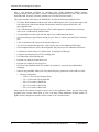
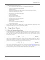
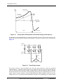
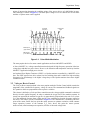
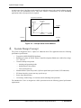
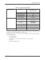
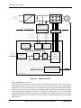
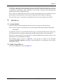
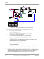
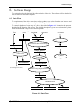
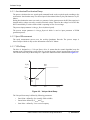
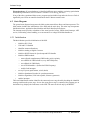
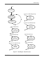
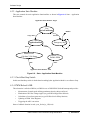
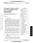
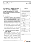
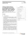
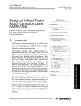
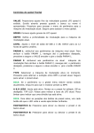
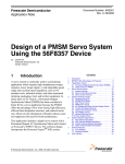
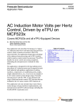
MOTOROLA Order by AN1911/D (Motorola Order Number) Rev. 0, 04/01 Semiconductor Application Note 3-Phase AC Motor Control with V/Hz Speed Open Loop Using DSP56F80X Design of Motor Control Application Based on Motorola Software Development Kit Petr Uhlir Zdenek Kubiczek 2. Motorola DSP Advantages and Features .................................... 1 3. Target Motor Theory ..................... 3 3.1 3-Phase AC Induction Motors Drives .............................................. 3 3.2 Volts per Hertz Control .................. 5 4. System Design Concept ................ 6 5. Hardware ....................................... 9 5.1 System Outline ............................... 9 5.2 High Voltage Hardware Set............ 9 6. Software Design .......................... 11 Introduction of Application Benefit This Application Note describes the design of a 3-phase AC induction motor drive with Volt per Hertz control in Opened Loop (hereinafter called V/Hz OL). It is based on Motorola’s 56F80X digital signal processor (DSP) which is dedicated for motor control applications. The system is designed as a motor control system for driving medium power, three phase AC induction motors and is targeted for applications in both industrial and appliance fields (e.g. washing machines, compressors, air conditioning units, pumps or simple industrial drives). The software design takes advantage of SDK (Software Development Kit) developed by Motorola. The drive to be introduced is intended as an example for a 3-phase AC induction motor drive. It serves as an example of AC V/Hz motor control system design using Motorola DSP with SDK support. It also illustrates the usage of dedicated motor control libraries that are included in the SDK. This Application Note includes the basic motor theory, system design concept, hardware implementation and software design including the PC Master visualization tool inclusion. 2. 1. Introduction of Application Benefit 1 Motorola DSP Advantages and Features The Motorola DSP56F80x family is well suited for digital motor control, combining the DSP’s calculation capability with MCU’s controller features on a single chip. These DSPs © Motorola, Inc. 2001 6.1 Data Flow ..................................... 11 6.1.1 Acceleration/Deceleration Ramp ........................................ 12 6.1.2 Speed Measurement ................. 12 6.1.3 V/Hz Ramp............................... 12 6.1.4 DC-Bus Voltage Ripple Elimination ............................... 13 6.1.5 PWM Generation ..................... 15 6.1.6 Fault Control ............................ 17 6.2 State Diagram ............................... 18 6.2.1 Initialization ............................. 18 6.2.2 Application State Machine ....... 20 6.2.3 Check Run/Stop Switch ........... 20 6.2.4 PWM Reload A ISR................. 20 6.2.5 PWM Fault A ISR .................... 21 6.2.6 ADC Conversion Complete ISR............................................ 21 6.2.7 ADC High Limit ISR ............... 21 6.2.8 ADC Low Limit ISR ................ 21 6.2.9 Timer OC LED ISR ................. 21 6.2.10 Timer OC Ramp ISR................ 21 7. SDK Implementation .................. 22 7.1 7.2 7.3 7.4 7.5 Drivers and Library Function ....... 22 Appconfig.h File ........................... 22 Drivers Initialization..................... 22 Interrupts....................................... 23 PC Master ..................................... 23 8. DSP Usage .................................. 23 9. References ................................... 24 Indirect Power Factor Correction Using DSP56F80X 1. Contents Motorola DSP Advantages and Features offer a rich dedicated peripheral set, including Pulse Width Modulation (PWM) modules Analog-to-Digital Converters (ADCs), Timers, communication peripherals (SCI, SPI, CAN), on-board Flash and RAM. Generally, all family members are well suited for motor control. The typical member of the family, the DSP56F805, provides the following peripheral blocks: • Two Pulse Width Modulator modules each with six PWM outputs, three Current Sense inputs, and four Fault inputs, fault tolerant design with dead-time insertion; supports both center- and edge-aligned modes • Two 12-bit Analog-to-Digital Converters (ADC) which support two simultaneous conversions; ADC can be synchronized by PWM modules • Two Quadrature Decoders each with four inputs or two additional Quad Timers • Two General Purpose Quad Timers totaling six pins: Timer C with two pins and Timer D with four pins • CAN 2.0 B Module with 2-pin port for transmit and receive • Two Serial Communication Interfaces, each with two pins (or four additional GPIO lines) • Serial Peripheral Interface (SPI) with configurable four-pin port (or four additional GPIO lines) • 14 dedicated General Purpose I/O (GPIO) pins, 18 multiplexed GPIO pins • Computer Operating Properly (COP) watchdog timer • Two dedicated external interrupt pins • External reset input pin for hardware reset • External reset output pin for system reset • JTAG/On-Chip Emulation (OnCE™) module for unobtrusive, processor speed-independent debugging • Software-programmable, Phase Lock Loop-based frequency synthesizer for the DSP core clock • Memory configuration — 32252 × 16-bit words of Program Flash — 512 × 16-bit words of Program RAM — 2K × 16-bit words of Data RAM — 4K × 16-bit words of Data Flash — 2K × 16-bit words of Boot Flash Other than the fast Analog-to-Digital converter and 16-bit Quadrature Timers, the most interesting peripheral from a motor control point of view is the Pulse Width Modulation (PWM) module. Its highly flexible configuration permits efficient control of AC induction motors. 2 Indirect Power Factor Correction Using DSP56F80X Target Motor Theory The PWM block has the following features: • Three complementary PWM signal pairs, or six independent PWM signals • Features of complementary channel operation • Deadtime insertion • Separate top and bottom pulse width correction via current status inputs or software • Separate top and bottom polarity control • Edge-aligned or center-aligned PWM signals • 15-bits of resolution • Half-cycle reload capability • Integral reload rates from one to 16 • Individual software-controlled PWM output • Programmable fault protection • Polarity control • 20-mA current sink capability on PWM pins • Write-protectable registers The AC Motor control utilizes the PWM block set in the complementary PWM mode, which configures the PWM output as a pair of complimentary channels. 3. Target Motor Theory 3.1 3-Phase AC Induction Motors Drives The AC induction motor is the workhorse in adjustable speed drive systems. The most popular type is a 3-phase squirrel-cage AC induction motor that is an efficient, low-cost, maintenance-free, low noise motor. The stator is supplied by a balanced three phase AC power source. The synchronous speed of the motor (ns) is given by 120 × fs n s = ------------------p [ rpm ] (EQ 3-1.) where fs is the synchronous stator frequency in Hz, and p is the number of stator poles. The AC induction motor produces zero torque at the synchronous frequency and therefore must run at the speed given by a load torque. The motor speed is characterized by a slip s r: ( ns – nr ) n sl s r = -------------------- = -----ns ns [-] (EQ 3-2.) where nr is the rotor mechanical speed and nsl is the slip speed, both in rpm. Figure 3-1 illustrates the torque characteristics and corresponding slip. As can be seen from EQ 3-1 and EQ 3-2, the motor speed is controlled by variation of a stator frequency with influence of the load torque. Indirect Power Factor Correction Using DSP56F80X 3 Torque Target Motor Theory Motor Torque Load Torque 1 Working Point s r 0.5 0 0 n n 0 Slip s r Motor Speed Generator Figure 3-1. Torque-Speed Characteristic at Constant Voltage and Frequency In adjustable speed applications the AC motors are powered by inverters. The inverter converts a DC power to AC power at required frequency and amplitude. The typical 3-phase inverter is illustrated in Figure 3-2. + DC-Bus C T 1 T 3 T 5 T 2 T 4 T 6 + - DC-Bus Ph. B Ph. A Ph. C 3-Phase AC Motor Figure 3-2. Three Phase Inverter The inverter consists of three half-bridge units where the upper and lower switch are controlled complementarily -- meaning when the upper one is turned on, the lower one is turned off and vice versa. As the power device’s turn-off time is longer than its turn-on, dead-time must be inserted between the turn off of one transistor of the half-bridge and turn on of its complementary device. The output voltage is mostly created by a Pulse Width Modulation (PWM) technique where an isosceles triangle carrier wave is compared with a fundamental-frequency sine modulating wave, and the natural 4 Indirect Power Factor Correction Using DSP56F80X Target Motor Theory points of intersection determine the switching points of the power devices of a half bridge inverter. This technique is shown in Figure 3-3. The three phase voltage waves are shifted 120o to each other and thus a 3-phase motor can be supplied. Generated Sine Wave PWM Carrier Wave 1 0 ωt -1 1 PWM Output T 1 (Upper Switch) PWM Output T 2 (Lower Switch) 0 ωt 1 0 ωt Figure 3-3. Pulse Width Modulation The most popular devices for motor control applications are Power MOSFETs and IGBTs. A Power MOSFET is a voltage controlled transistor designed for high frequency operation. It has low voltage drop and thus low power losses. However, the saturation and temperature sensitivity limit the MOSFET’s application in high power circuits. An Insulated Gate Bipolar Transistor (IGBT) is a bipolar transistor controlled by a MOSFET on its base. The IGBT requires low drive current, has fast switching time and is suitable for high switching frequencies. Its disadvantage is the higher voltage drop of the bipolar transistor that causes higher conduction losses. 3.2 Volts per Hertz Control The Volt per Hertz control method is the most popular method of Scalar Control which controls the magnitude of the variable like frequency, voltage or current. The command and feedback signals are DC quantities which are proportional to the respective variables. This scheme is defined as a Volts per Hertz control because the voltage applied command is calculated directly from the applied frequency in order to maintain the air-gap flux of the machine constant. In steady state operation the machine air-gap flux is approximately proportional to the ratio Vs/fs, where Vs is the amplitude of motor phase voltage and fs is the synchronous electrical frequency applied to the motor. The control system is illustrated in Figure 3-4. The characteristic is defined by the base point of the motor. Below the base point the motor operates at optimum excitation, called constant torque operation, because of the constant V s/fs ratio. Above this point the motor operates under-excited, called constant power operation, because of the rated voltage limit. Indirect Power Factor Correction Using DSP56F80X 5 System Design Concept A simple open-loop Volts/Hertz speed control for an induction motor is the control technique targeted for low cost, low performance drives. This basic scheme is unsatisfactory for more demanding applications where speed precision is required. Volt per Hertz Characteristic Motor Base Point Voltage 100% Amplitude Base Frequency Frequency Frequency Frequency Figure 3-4. Volts per Hertz Control Method 4. System Design Concept The system is designed to drive a 3-phase AC induction motor. The application meets the following performance specifications: • Targeted for DSP56F80XEVM platforms • Running on 3-phase AC BLDC Motor Control Development Platform at variable line voltage 115 - 230V AC • Control technique incorporates — motoring and generating mode — both direction of the rotation — V/Hz speed open loop • Manual Interface (Start/Stop switch, Up/Down push button speed control, LED indication) • PC Master Interface (motor start/stop, speed set-up) • Power Stage Identification • Overvoltage, Undervoltage, Overcurrent, and Overheating Fault protection The introduced AC drive is designed as a DSP system that meets the following general performance requirements: 6 Indirect Power Factor Correction Using DSP56F80X System Design Concept Table 4-1. Motor / Drive Specification Motor Characteristics: Drive Characteristics: Motor Type 4 poles, three phase, star connected, squirrel cage AC motor (standard industrial motor) Speed Range: < 5000 rpm Base Electrical Frequency: 50 Hz Max. Electrical Power: 180 W Delta Voltage (rms): 200V (Star) Transducers: IRC -1024 pulses per rev. Speed Range < 2250 rpm @ 230 V <1200 rpm @ 115 V Line Input: 230V / 50Hz AC 115V / 60Hz AC Max DC Bus Voltage 400 V Control Algorithm Open Loop Control Optoisolation Required Type Varying Load Characteristic: The DSP runs the main control algorithm. According to the user interface input and feedback signals, it generates 3-phase PWM output signals for the motor inverter. A standard system concept is chosen for the drive (see Figure 4-1). The system incorporates the following hardware boards: • Power Supply Rectifier • Three-phase inverter • Feedback sensors: speed, DC-Bus Voltage, DC-Bus Current, Temperature • Optoisolation • Evaluation Board DSP56F80X Indirect Power Factor Correction Using DSP56F80X 7 System Design Concept 5HFWLILHU 7KUHH3KDVH,QYHUWHU a /LQH 9ROWDJH 9+] '&%XV SK $&0 ,VRODWLRQ%DUULHU 2SWRLVRODWLRQ 2SWRLVRODWLRQ 2YHU&XUUHQW 2YHU9ROWDJH 7HPSHUDWXUH '&%XV9ROWDJH 7HPSHUDWXUH 9ROWDJH 3URFHVVLQJ ,5& 7HPSHUDWXUH &XUUHQW 9ROWDJH6HQVLQJ 3:0 )DXOWV 3URFHVVLQJ $'& '&%XV9ROWDJH 6SHHG 6HWXS 6SHHG &RPPDQG 3URFHVVLQJ 9+] 9 '&%XV 9 5LSSOH &DQFHO ) 3:0 *HQHUDWRU ZLWK 'HDG7LPH 6SHHG3URFHVVLQJ 0HDVXUHG6SHHG IRU3&0DVWHU ,QFUHPHQWDO'HFRGHU '63)[ Figure 4-1. System Concept The control process is as follows: When the Start command is accepted (using the Start/Stop Switch), the state of the inputs is periodically scanned. According to the state of the control signals (Start/Stop switch, speed up/down buttons or PC Master set speed) the speed command is calculated using an acceleration/deceleration ramp. With the use of the V/Hz ramp the corresponding voltage is calculated and then DC-Bus Ripple Cancellation function eliminates the influence of the DC Bus voltage ripples to the generated phase voltage amplitude. The PWM generation process calculates a three phase voltage system at required amplitude and frequency which includes dead time. Finally, the 3-phase PWM Motor Control signals are generated. 8 Indirect Power Factor Correction Using DSP56F80X Hardware The DC-Bus voltage and power stage temperature are measured during the control process. They are overvoltage, undervoltage, and overheating protection of the drive. Both undervoltage protection and overheating are performed by ADC and software. The DC Bus overcurrent and overvoltage fault signals are connected to a PWM fault input. If any of the above mentioned faults occurs, the motor control PWM outputs are disabled in order to protect the drive and the fault state of the system is displayed on the PC Master control page. The speed of the motor is measured by the Quadrature Decoder just for displaying in PC Master. 5. Hardware 5.1 System Outline The motor control system is designed to drive the 3-phase AC motor in a speed open loop. There are more software versions targeted for a concrete DSP and Evaluation Module (DSP/EVM): • DSP56F80X The hardware setup for a concrete DSP/EVM differs only by Evaluation Module (EVM) module used. The designed software is capable of running only on High Voltage hardware set described below. Other power module boards will be denied due to board identification built into the software. This feature protects you against hardware damage. The hardware setup is shown in Figure 4-1, and can also be found in the document Targeting_DSP5680X_Platform, according to targeted DSP/EVM. That documents also describes EVM jumper settings. 5.2 High Voltage HW set The system configuration is shown in Figure 5-1. Indirect Power Factor Correction Using DSP56F80X 9 Hardware 9'& *1' ZIODWULEERQ FDEOHJUD\ 8 Light Blue 1 - SK$&%/'& - +LJK9ROWDJH 3RZHU6WDJH Green-Yellow 3( FDEOHJUD\ 8 -3-3 Black / ZIODWULEERQ 8 2SWRLVRODWLRQ - - %RDUG &RQWUROOHU%RDUG - - (&237 --- SLQFRQQ Black White Red 0% $03$ 0RWRU%UDNH (&237+,9$&%/'& (QFRGHU&RQQ7DEOH $09 6*1 &RQWUROHU Red White Black - ,QFUHPHQWDO(QFRGHU %DXPHU(OHFWULF &RQQ '63) - '63) - '63) - (&075+,9$& %+.$ +DOO6HQVRU , (QFRGHU $ 1RWXVHGLQ DSSOLFDWLRQ ,QFUHPHQWDO(QFRGHU&DEOH!&RQQHFWRU7DEOH &DEOH:LUH&RORU 'HVF %URZQ 9'& :KLWH6KLHOGLQJ *URXQGDQG6KLHOGLQJ *UHHQ 3KDVH$ <HOORZ 3KDVH% 3LQN ,QGH[ 8QXVHG 8QXVHG Figure 5-1. High Voltage Hardware System Configuration All the system parts are supplied and documented according the following references: • U1 - Controller Board for DSP56F80X: — supplied as: DSP5680XEVM — described in: DSP Evaluation Module Hardware User’s Manual • U2 - 3 ph AC/BLDC High Voltage Power Stage — supplied in kit with Optoisolation Board as: ECOPTHIVACBLDC — described in: 3 Phase Brushless DC High Voltage Power Stage • U3 - Optoisolation Board — supplied with 3 ph AC/BLDC High Voltage Power Stage as: ECOPTHIVACBLDC — or supplied alone as: ECOPT - optoisolation board — described in: Optoisolation Board User’s Manual • MB1 Motor-Brake AM40V + SG40N — supplied as: ECMTRHIVAC Warning: It is strongly recommended to use opto-isolation (optocouplers and optoisolation amplifiers) during the development time to avoid any damage to the development equipment. Notes: The detailed description of individual boards can be found in comprehensive User’s Manuals belonging to each board. The user manual incorporates the schematic of the board, description of individual function blocks and bill of materials. The individual boards can be ordered from Motorola as a standard product from http://mot-sps.com/motor/devtools/index.html 10 Indirect Power Factor Correction Using DSP56F80X Software Design 6. Software Design This section describes the design of the software blocks of the drive. The software will be described in terms of Data Flow and State Diagrams. 6.1 Data Flow The requirements of the drive dictate that software gathers some values from the user interface and sensors, processes them and generates 3-phase PWM signals for the inverter. The control algorithm of open loop AC drive is described in Figure 6-1. It contains the processes described in the following sub-sections. The detailed description is given to the subroutines 3-phase PWM calculation and Volt per Hertz control algorithm. Temperature (A/D) DC-Bus Voltage (A/D) PC MASTER SPEED SETTING INCREMENTAL ENCODER Omega_desired u_dc_bus Speed Measurement Acceleration/Deceleration Ramp Temperature Omega_measured Omega_required Fault Control PC_Master V/Hz Ramp DriveFaultStatus AmplitudeVoltScale PWM Faults (OverVoltage/OverCurrent) DC-Bus Voltage Ripple Elimination Amplitude PWM Generation PVAL0 PVAL2 PVAL4 Figure 6-1. Data Flow Indirect Power Factor Correction Using DSP56F80X 11 Software Design 6.1.1 Acceleration/Deceleration Ramp The process calculates the new actual speed command based on the required speed according to the acceleration / deceleration ramp. The desired speed is determined either by the push buttons or by PC Master During deceleration the motor can work as a generator. In the generator state the DC-Bus capacitor is charged and its voltage can easily exceed its maximal voltage. Therefore the voltage level in DC-Bus link is controlled by a resistive brake which is operating in case of overvoltage. The process input parameter is Omega_Desired (desired speed). The process output parameter is Omega_Required which is used as input parameter of PWM generation process. 6.1.2 Speed Measurement The speed measurement process uses the on-chip Quadrature Decoder. The process output is MeasuredSpeed which is only used as information value in PC Master. 6.1.3 V/Hz Ramp The drive is designed as a “Volt per Hertz“ drive. It means that the control algorithm keeps the constant motor’s magnetizing current (flux) by varying the stator voltage in proportion to frequency. The common used Volt per Hertz ramp of a 3-phase AC induction motor is illustrated in Figure 6-2. V (%) Base Point Vbase Vboost Vstart Start Point Boost Point fboost fbase f (Hz) Figure 6-2. Volt per Hertz Ramp The Volt per Hertz ramp is defined by following parameters: 12 • Base Point - defined by fbase (usually 50Hz or 60Hz) • Boost Point- defined by Vboostand fboost • Start Point - defined by Vstart at zero Frequency Indirect Power Factor Correction Using DSP56F80X Software Design The ramp profile fits the specific motor and can be easily changed to accommodate different ones. Process Description This process provides voltage calculation according to V/Hz ramp. The input of this process is generated by desired inverter frequency Omega_Required. The output of this process is AmplitudeVoltScale that is a parameter required by DC-Bus Voltage Ripple Elimination process. 6.1.4 DC-Bus Voltage Ripple Elimination Process Description This process eliminates the influence of the DC-Bus voltage variation (ripples) toward the generated phase voltage sinewaves. In fact, it lowers the 50 or 60 Hz acoustic noise of the motor. Another positive aspect is that due to this function-generated phase voltage, it is independent of the level of DC-Bus voltage. So the application is adaptable in both American and European power supply systems. The process is performed by function mcgenDCBVoltRippleElim which converts the phase voltage amplitude (AmplitudeVoltScale) to the sine wave amplitude (Amplitude) based on the actual value of the DC-Bus voltage (u_dc_bus) and inverse value of the modulation index (ModulationIndexInverse). The modulation index is the ratio between the maximum amplitude of the first harmonic of phase voltage (in voltage scale) and half of the DC Bus voltage (in voltage scale), which is defined by the following formula: (1) U phasemax 2 m i = ------------------------- = ------1--3 ⋅u 2 DCBus (EQ 6-1.) The modulation index is specific to given 3-phase generation algorithm and in this application is 1.27. The top chart in Figure 6-3 demonstrates how the Amplitude (in scale of generated sine wave amplitude) is counter-modulated in order to eliminate the DC-Bus ripples. The second chart shows the duty cycles generated by one of the 3-ph wave generation functions. The third chart contains sine-waves of the phase-to-phase voltages actually applied to the 3-phase motor. Indirect Power Factor Correction Using DSP56F80X 13 Software Design XBGFBEXV>8PD[@ $PSOLWXGH9ROW6FDOH>8PD[@ $PSOLWXGH>$PSOPD[@ 'XW\&\FOH3KDVH$ 'XW\&\FOH3KDVH% 'XW\&\FOH3KDVH& 3K$3K%>9@ 3K%3K&>9@ 3K&3K$>9@ Figure 6-3. 3-ph Wafeforms with DC Bus Voltage Ripple Elimination 14 Indirect Power Factor Correction Using DSP56F80X Software Design 6.1.5 PWM Generation Process Description This process generates a system of three phase sinewaves with addition of third harmonic component shifted 120o to each other using mcgen3PhWaveSine3rdHIntp function from the Motor Control function library. The function is based on a fixed wave table describing the first quadrant of sine wave stored in Data memory of the DSP. Due to symmetry of the sine function, data in other quadrants are calculated using the data of first quadrant. This saves data memory space. In figure Figure 6-4 there is an explanation of sinewave generation for phase A (for simplicity). Phase B and C are shifted 120o with respect to Phase A. [III 3KDVH,QFUHPHQW $FWXDO3KDVHQ DPSOLWXGH DPSOLWXGH $FWXDO3KDVHQ [ 'XW\&\FOH3KDVH$ [ [ R [III R Figure 6-4. Sinewave Generation Each time the waveform generation function is called, ActualPhase from previous step is updated by PhaseIncrement, and according calculated phase the value of sine is fetched from the sine table (using function tfr16SinPIxLUT from DSP functional library). Then it’s multiplied by the Amplitude and passed to the PWM. For explaining the 3 phase waveform generation with 3rh harmonic addition see the following formulas: Indirect Power Factor Correction Using DSP56F80X 15 Software Design 1 1 PWMA = ------- ⋅ Amplitude ⋅ sin α + --- ⋅ sin 3α + 0.5 6 3 1 1 PWMB = ------- ⋅ Amplitude ⋅ sin ( α – 120 0 ) + --- ⋅ sin 3α + 0.5 6 3 (EQ 6-1.) 1 1 PWMC = ------- ⋅ Amplitude ⋅ sin ( α – 240 0 ) + --- ⋅ sin 3α + 0.5 6 3 where PWMA, PWMB and PWMC are calculated duty cycles passed to PWM driver and Amplitude determines the level of Phase voltage Amplitude. The process is performed in a PWM reload callback function pwm_Reload_A_ISR and is accessed regularly at the rate given by the set PWM reload frequency. This process has to be repeated often enough compared to the wave frequency in order to generate the correct wave shape. Therefore for 16kHz PWM frequency it is called each 4th PWM pulse and thus the PWM registers are updated in 4kHz rate (each 250µsec). Figure 6-5 shows the dutycycles generated by the mcgen3PhWaveSine3rdHIntp function when Amplitude is 1 (100%). VW+DUPRQLF$ VW+DUPRQLF% VW+DUPRQLF% UG+DUPRQLF 'XW\&\FOH3KDVH$ 'XW\&\FOH3KDVH% 'XW\&\FOH3KDVH& Figure 6-5. 3-ph Sine Waves with 3rd Harmonic Injection, Amplitude = 100% Figure 6-6 shows the dutycycles generated by the mcgen3PhWaveSine3rdHIntp function when Amplitude is 0.5 (50%). 16 Indirect Power Factor Correction Using DSP56F80X Software Design VW+DUPRQLF$ VW+DUPRQLF% VW+DUPRQLF% UG+DUPRQLF 'XW\&\FOH3KDVH$ 'XW\&\FOH3KDVH% 'XW\&\FOH3KDVH& Figure 6-6. 3-ph Sine Waves with 3rd Harmonic Injection, Amplitude = 50% Inputs of the process: • Amplitude - obtained from DC-Bus Ripple Elimination process • Omega_required - obtained from Acceleration/ Deceleration Ramp process Output of the process: Results calculated by mcgen3PhWaveSine3rdHIntp function are directly passed to PWM Value Registers using PWM driver. 6.1.6 Fault Control This process is responsible for fault handling. The software accommodates five fault inputs: overcurrent, overvoltage, undervoltage, overheating and wrong identified hardware. Overcurrent: In case of overcurrent in DC-Bus link, the external hardware provides a rising edge on the fault input pin FAULTA1 of the DSP. This signal immediately disables all Motor Control PWM’s outputs (PWM1 - PWM6) and sets DC_Bus_OverCurrent bit of DriveFaultStatus variable. Overvoltage: In case of overvoltage in DC-Bus link, the external hardware provides a rising edge on the fault input pin FAULTA0 of the DSP. This signal immediately disables all Motor Control PWM’s outputs (PWM1 - PWM6) and sets DC_Bus_OverVoltage bit of DriveFaultStatus variable. Undervoltage: The DC Bus voltage sensed by ADC is compared with the limit within the software. In case of undervoltage after a period defined by UnderVoltage_Count all Motor Control PWM outputs are disabled and DriveFaultStatus variable is set to DC_Bus_UnderVoltage. Overheating: The Temperature of the power module sensed by ADC is compared with the limit within the software. In case of overheating after a period defined by OverHeating_Count all Motor Control PWM outputs are disabled and DriveFaultStatus variable is set to OverHeating Indirect Power Factor Correction Using DSP56F80X 17 Software Design Wrong hardware: If wrong hardware is identified (different power module or missing optoisolation board) during initialization, DriveFaultStatus variable is set to Wrong_Hardware. If any of the above mentioned faults occurs, program run into infinite loop and waits for reset. Fault is signalled by user LEDs on controller board and on the PC Master control screen. 6.2 State Diagram The general state diagram incorporates the Main routine entered from Reset, and interrupt states. The Main routine includes the initialization of the DSP and the main loop. The main loop incorporates Initialization State, Application State Machine and Check Run/Stop Switch state. The interrupt states provides calculation of the actual speed of motor, PWM reload interrupt, ADC service, Limit analog values handling, over current and over voltage PWM fault handler etc. 6.2.1 Initialization The Main Routine provides initialization of the DSP: • initializes PLL Clock • COP and LVI disabled • identifies connected hardware • initializes Analog to Digital Converter • initializes POSIX timers for Speed ramp and LED handler • initializes PWM module: — center aligned complementary PWM mode, positive polarity — sets callback for PWM reload to (every 4th. PWM pulse) — sets callback for PWM faults — sets of PWM modulus - (defines the PWM frequency) — enables fault interrupts • sets-up I/O ports (push buttons, switch, brake) • initializes Quadrature Decoder for speed measurement • initializes algorithms (V/Hz look-up table, Sinewave generator) • enables interrupts The board identification routine identifies the connected power stage board by decoding the identified message send from the power stage. In case the wrong power stage is connected, the program goes to the infinite loop, displays the fault status on the LED. The state can be left only by the RESET. 18 Indirect Power Factor Correction Using DSP56F80X Software Design reset Initialization done OC Timer for LED handling Interrupt Application State Machine Timer OC LED Subroutine done Check Run/Stop Switch done OC Timer for Speed Ramp Interrupt done Timer OC Speed Ramp Subroutine ADC low limit Interrupt ADC Low Limit Interrupt Subroutine done done ADC high limit Interrupt ADC High Limit Interrupt Subroutine PWM Reload A Interrupt Subroutine done done ADC conversion complete Interrupt ADC Interrupt Subroutine done PWM A Reload Interrupt PWM A Fault Interrupt PWM Fault A Interrupt Subroutine done Figure 6-7. State Diagram - General Overview Indirect Power Factor Correction Using DSP56F80X 19 Software Design 6.2.2 Application State Machine This state controls the main application functionalities as shown in Figure 6-8: State - Application State Machine. Application State Machine - Begin Test DriveFaultStatus RESET NO_FAULT FAULT Test ApplicationMode RUN Emergency Stop STOP Enable PWM Calculate V/Hz Ramp Speed = 0 Disable PWM done done Application State Machine - End Figure 6-8. State - Application State Machine 6.2.3 Check Run/Stop Switch In this state Run/Stop switch is checked and accordingly that Application Mode is set to Run or Stop. 6.2.4 PWM Reload A ISR This subroutine is called at PWM A (or PWM in case of DSP56F803) Reload Interrupt and provides: • Measurement of actual speed utilizing quadrature decoder (MeasuredSpeed) • Elimination of DC-Bus Voltage ripples (mcgenDCBVoltRippleElim function) • Calculation of waveform generator (mcgen3PhWaveSine3rdHIntp function) • Updating of PWM Value Registers • Triggering the ADC conversion Name of callback function in code: pwm_Reload_A_ISR(void). 20 Indirect Power Factor Correction Using DSP56F80X Software Design 6.2.5 PWM Fault A ISR This disables the PWM module and sets DriveFaultStatus|=DC_Bus_OverVoltage or DC_Bus_OverCurrent according to fault input pin level in case of over voltage or over current in DC-Bus line. Name of callback function in code: pwm_Fault_A_ISR(void) This subroutine is called at PWM A (or PWM in case of DSP56F803) Fault Interrupt. 6.2.6 ADC Conversion Complete ISR The following analog inputs are read: • DC Bus Voltage • DC Bus Current • Temperature of Power Stage Module Also the detection of faults caused by Over heating and Under voltage is performed in this subroutine. Name of callback function in code: ADC_Callback_ISR This subroutine is called at ADC conversion completion. 6.2.7 ADC High Limit ISR This subroutine turns on the resistive brake in DC Bus link when actual voltage in DC-Bus u_dc_bus is higher than BRAKE_HIGH_LIMIT. Name of callback function in code: ADC_High_Limit_CallBack_ISR. 6.2.8 ADC Low Limit ISR This subroutine turns off the resistive brake in DC Bus link when actual voltage in DC-Bus u_dc_bus is lower than BRAKE_LOW_LIMIT. Name of callback function in code: ADC_Low_Limit_CallBack_ISR. 6.2.9 Timer OC LED ISR This subroutine performs the LED flashing according the state of application Name of callback function in code: LedISR (void). Access frequency is defined by constant TMR_1_PERIOD in definition section of program. 6.2.10 Timer OC Ramp ISR This subroutine performes the calculation of Speed Ramp. Name of callback function in code: RampISR (void). Access frequency is defined by constant TMR_2_PERIOD in definition section of program. Indirect Power Factor Correction Using DSP56F80X 21 SDK Implementation 7. SDK Implementation The Motorola Embedded SDK is a collection of APIs, libraries, services, rules and guidelines. This software infrastructure is designed to let DSP5680x software developers create high-level, efficient, portable code. This chapter describes how the AC V/Hz motor control application is written under SDK. 7.1 Drivers and Library Function The AC V/Hz motor control application uses the following drivers: • ADC driver • Timer driver • Quadrature Timer driver • Quadrature Decoder driver • PWM driver • LED driver • Switch driver • Button driver • Brake driver All drivers except Timer driver are included in bsp.lib library. The Timer driver is included in sys.lib library. The AC V/Hz motor control application uses the following library functions: • boardId (board identification, bsp.lib library) • mcgen3PhWaveSine3rdHIntp (waveform generation function, mcfunc.lib library) • mcgenDCBVoltRippleElim (DC-Bus Ripple cancellation function, mcfunc.lib library) • lutGetValue (look-up table - performing V/Hz ramp, mcfunc.lib library) • rampGetValue (speed ramp, mcfunc.lib) 7.2 Appconfig.h File The purpose of the appconfig.h file is to provide a mechanism for overwriting default configuration settings which are defined in the config.h file. There are two appconfig.h files The first appconfig.h file is dedicated for External RAM (..\ConfigExtRam directory) and second one is dedicated for FLASH memory (..\ConfigFlash directory). In case of AC V/Hz motor control application both files are identical. The appconfig.h file is divided into two sections. The first section defines which components of SDK libraries are included to application; the second part overwrites standard setting of components during their initialization. 7.3 Drivers Initialization Each peripheral on the DSP chip or on the EVM board is accessible through a driver. The driver initialization of all used peripherals is described in this chapter. For a detailed descriptions of drivers, see document Embedded SDK Targeting Motorola DSP5680x Platform. 22 Indirect Power Factor Correction Using DSP56F80X DSP Usage To use the driver the following step must be done: • include the driver support to the appconfig.h • fill configuration structure in the application code for specific drivers (depends on driver type) • initialize the configuration setting in appconfig.h for specific drivers (depends on driver type) • call the open (create) function The access to individual driver functions is provided by the ioctl function calls. 7.4 Interrupts The SDK serves the interrupt routines calls and automatically clears interrupt flags. The user defines the callback functions called during interrupts. The callback functions are assigned during the driver’s initialization - open(). The callback function assignment is defined as one item of initialization structure which is used as a parameter of function open(). Some drivers define the callback function in appconfig.h file. 7.5 PC Master PC Master was designed to provide the debugging, diagnostic and demonstration tools for development of algorithms and applications. It consists of components running on PC and parts running on the target development board. The PC Master application is part of the Motorola Embedded SDK and may be selectively installed during SDK installation. To enable the PC Master operation on the target board application, the following lines must be added to the appconfig.h file: #define INCLUDE_SCI #define INCLUDE_PCMASTER /* SCI support */ /* PC Master support */ It automatically includes the SCI driver and installs all necessary services. The baud rate of the SCI communication is 9600Bd and is set automatically by PC Master driver. The detailed PC Master description is provided by the PC Master User Manual. 8. DSP Usage Table shows how much memory is needed to run the 3-phase AC V/Hz open loop application. A part of the DSP memory is still available for other tasks. Table 8-1. RAM and FLASH Memory Usage for SDK2.3 and CW 4.0 Memory (in 16 bit Words) Available DSP56F803 DSP56F805 Used Application + Stack Used Application without PC Master, SCI Program FLASH 32K 14074 6837 Data RAM 2K 845 + 352 stack 513 + 352 stack Data Flash 4K 430 430 Indirect Power Factor Correction Using DSP56F80X 23 9. References 3 Phase Brushless DC High Voltage Power Stage, MEMC3BLDCPSUM/D, Motorola DSP56F800 16-bit Digital Signal Processor, Family Manual, DSP56F800FM/D, Motorola DSP56F80x 16-bit Digital Signal Processor, User’s Manual, DSP56F801-7UM/D, Motorola DSP Evaluation Module Hardware User’s Manual, DSP56F80XEVMUM/D, Motorola Green Electronics / Green Bottom Line Lee H. Goldberg - Chapter 2 Energy Efficient Three Phase AC Motor Drives for Appliance and Industrial Applications by Radim Visinka Low Cost 3-phase AC Motor Control System Based On MC68HC908MR24. Motorola Semiconductor Application Note, AN1664, 1998 Motorola Software Development Kit Optoisolation Board User’s Manual, MEMCOBUM/D, Motorola Web page: http://e-www.motorola.com/motor/ OnCETM is a registered trademark of Motorola, Inc. Motorola reserves the right to make changes without further notice to any products herein. Motorola makes no warranty, representation or guarantee regarding the suitability of its products for any particular purpose, nor does Motorola assume any liability arising out of the application or use of any product or circuit, and specifically disclaims any and all liability, including without limitation consequential or incidental damages. “Typical” parameters which may be provided in Motorola data sheets and/or specifications can and do vary in different applications and actual performance may vary over time. All operating parameters, including “Typicals” must be validated for each customer application by customer’s technical experts. Motorola does not convey any license under its patent rights nor the rights of others. Motorola products are not designed, intended, or authorized for use as components in systems intended for surgical implant into the body, or other applications intended to support or sustain life, or for any other application in which the failure of the Motorola product could create a situation where personal injury or death may occur. Should Buyer purchase or use Motorola products for any such unintended or unauthorized application, Buyer shall indemnify and hold Motorola and its officers, employees, subsidiaries, affiliates, and distributors harmless against all claims, costs, damages, and expenses, and reasonable attorney fees arising out of, directly or indirectly, any claim of personal injury or death associated with such unintended or unauthorized use, even if such claim alleges that Motorola was negligent regarding the design or manufacture of the part. Motorola and M are registered trademarks of Motorola, Inc. Motorola, Inc. is an Equal Opportunity/Affirmative Action Employer. How to reach us: USA/EUROPE/Locations Not Listed: Motorola Literature Distribution: P.O. Box 5405, Denver, Colorado 80217. 1-303-675-2140 or 1-800-441-2447 JAPAN: Motorola Japan Ltd.; SPS, Technical Information Center, 3-20-1 Minami-Azabu. Minato-ku, Tokyo 106-8573 Japan. 81-3-3440-3569 ASIA/PACIFIC: Motorola Semiconductors H.K. Ltd.; Silicon Harbour Centre, 2 Dai King Street, Tai Po Industrial Estate, Tao Po, N.T., Hong Kong. 852-26668334 Technical Information Center: 1-800-521-6274 HOME PAGE: http://motorola.com/semiconductors/dsp MOTOROLA HOME PAGE: http://motorola.com/semiconductors/ AN1911/D