1
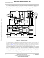
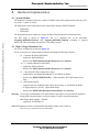
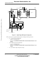
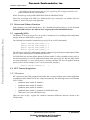
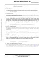
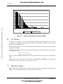
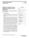
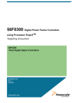
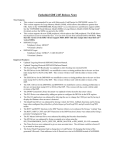
Freescale Semiconductor, Inc.
MOTOROLA
Order by AN1918/D
(Motorola Order Number)
Rev. 0, 6/01
Indirect Power Factor
Correction for 3-Phase AC
Motor Control with V/Hz
Speed Open Loop
Application Using
DSP56F80x
Design of Indirect Power Factor Correction
Contents
1. Introduction of Application Benefit ...1
2. Motorola DSP Advantages and
Features .................................... 2
3. System Design Concepts............... 3
4. Hardware Implementation ............. 5
4.1 System Outline ............................... 5
4.2 High Voltage Hardware Set............ 5
5. Software Implementation .............. 7
1.
Introduction of Application
Benefit
This Application Note describes the design of a Indirect
Power Factor Correction (Indirect PFC) for 3-phase AC
Motor V/Hz Speed Open Loop application. It is based on
Motorola’s 56F80X digital signal processor (DSP) which is
dedicated for motor control applications.
Most practical electronic power supplies consist of a
conventional single-phase full-bridge rectifier and filter
stages. As is well-known, this type of circuit draws high
current levels from the power line and produces a high level
of harmonics. This harmonic distortion and low power factor
(PF) reduce the maximum power available from the power
lines and reduce the efficiency of the electrical supply
networks. The European Normative EN 61000-3-2 defines
the limits of the harmonic content of the input current for the
power line supplied equipment. To meet these requirements,
new designs require the use of an active power factor
correction (PFC) at the input. The PFC emulates the ideal
ohmic load by electronically controlling input current drawn
from the line.
5.1 Files ................................................ 7
5.2 Drivers and Library Function ......... 8
5.3 Appconfig.h File ............................. 8
5.4 PFC Control Integration ................. 8
5.4.1 Resources ................................... 8
5.4.2 Modification ............................... 8
5.4.3 Initialization ............................... 9
5.4.4 PFC Control Enable ................... 9
5.4.5 PFC Control Disable .................. 9
5.5 Input Current Harmonics Contents. 9
6. PC Master .................................... 10
7. Memory Usage ............................ 10
8. References ................................... 11
There are many specific ICs available on the market to do the
PFC task. Those approach require additional electronic
components, increasing the system cost and complexity. On
the other hand, there is a way to implement PFC control
© Motorola, Inc., 2001
For More Information On This Product,
Go to: www.freescale.com
Indirect Power Factor Correction
Freescale Semiconductor, Inc...
Semiconductor Application Note
Freescale Semiconductor, Inc.
Motorola DSP Advantage and Features
through the DSP in addition to the main control tasks like motor control, etc. The use of a digital PFC
replaces a number of ICs and reduces the system cost. Another benefit of the software implementation
is easy modification without changing the hardware.
2.
Motorola DSP Advantage and Features
The members of the Motorola DSP56F80x family are well suited for digital motor control, combining
the DSP’s calculation capability with an MCU’s controller features on a single chip. These DSPs offer
many peripherals, including Pulse-Width-Modulation (PWM) unit, Analog-to-Digital Converter
(ADC), Timers, communication peripherals (SCI, SPI, CAN), on-board Flash and RAM.
Freescale Semiconductor, Inc...
The typical member of the family, the DSP56F805, provides the following peripheral blocks:
•
Two Pulse Width Modulator modules (PWMA & PWMB), each with six PWM outputs, three
Current Status inputs, and four Fault inputs, fault tolerant design with deadtime insertion,
supports both Center- and Edge- aligned modes
•
Twelve-bit Analog to Digital Convertors (ADCs), supporting two simultaneous conversions
with dual 4-pin multiplexed inputs; ADC can be synchronized by PWM modules
•
Two Quadrature Decoders (Quad Dec0 & Quad Dec1), each with four inputs, or two
additional Quad Timers A & B
•
Two dedicated General Purpose Quad Timers totalling 6 pins: Timer C with 2 pins and Timer
D with 4 pins
•
CAN 2.0 A/B Module with 2-pin ports used to transmit and receive
•
Two Serial Communication Interfaces (SCI0 & SCI1), each with two pins, or four additional
GPIO lines
•
Serial Peripheral Interface (SPI), with configurable 4-pin port, or four additional GPIO lines
•
Computer Operating Properly (COP) timer
•
Two dedicated external interrupt pins
•
Fourteen dedicated General Purpose I/O (GPIO) pins, 18 multiplexed GPIO pins
•
External reset pin for hardware reset
•
JTAG/On-Chip Emulation (OnCE)
•
Software-programmable, Phase Lock Loop-based frequency synthesizer for the DSP core
clock
•
Memory configuration
— 32252 × 16-bit words of Program Flash
— 512 × 16-bit words of Program RAM
— 2K × 16-bit words of Data RAM
— 4K × 16-bit words of Data Flash
— 2K × 16-bit words of Boot Flash
Other than the fast Analog-to-Digital converter and 16-bit Quadrature Timers, the most interesting
peripheral from a motor control point of view is the Pulse Width Modulation (PWM) module. Its
configuration permits efficient control of AC motors.
2
Indirect Power Factor Correction
For More Information On This Product,
Go to: www.freescale.com
Freescale Semiconductor, Inc.
System Design Concepts
Freescale Semiconductor, Inc...
The PWM has the following features:
•
Three complementary PWM signal pairs, or six independent PWM signals
•
Complementary channel operation
•
Deadtime insertion
•
Separate top and bottom pulse width correction via current status inputs or software
•
Separate top and bottom polarity control
•
Edge-aligned or center-aligned PWM signals
•
15-bits of resolution
•
Half-cycle reload capability
•
Integral reload rates from one to 16
•
Individual software-controlled PWM output
•
Programmable fault protection
•
Polarity control
•
20-mA current sink capability on PWM pins
•
Write-protectable registers
The AC Motor control utilizes the PWM block set in the complementary PWM mode, which
configures the PWM output as a pair of complimentary channels.
3.
System Design Concepts
The system has all of the basic characteristics of both Digital Power Factor Correction and 3-phase AC
motor V/Hz Open Loop applications described below:
•
Motor Control — Targeted for DSP56F803/805EVM platforms
— Running on 3-phase AC/BLDC Motor Control Development Platform at single line
voltage 360V DC +/- 10%
— Control technique incorporates
— V/Hz speed open loop
— bi-directional rotation
— motoring and regenerating mode
— Overvoltage, Undervoltage, Overcurrent, and Temperature Fault protection
— PC Master and Manual Interface
— Power Stage Identification
•
PFC Control — Input power supply voltage 115-230V AC
— Input power supply frequency 50/60 Hz
— Nominal output voltage 360V DC +/- 10%.
— Nominal output power 180W
— Input current harmonic content will comply with standard IEC 1000-3-2
Indirect Power Factor Correction
For More Information On This Product,
Go to: www.freescale.com
3
Freescale Semiconductor, Inc.
System Design Concepts
The system is designed to integrate PFC control with a real motor control application. The base is the
3-phase AC Motor V/Hz Speed Open Loop application. The DSP runs the main control algorithm. It
generates a 3-phase PWM output signal for the motor according to the user’s input. The DSP also
controls the power factor correction hardware that provides the power supply for the motor.
DC-Bus
3-ph
AC M
Freescale Semiconductor, Inc...
~115-230V
50/60Hz
pulse wide modulator
&
Zero crossing
detection
Pulse wide
modulation
Input
frequency
measurement.
Milestone
generation.
Base
frequency
Inhibit
output
IRC
Temperature,
Current & Voltage
sensors
Temperature, voltage
and fault processing
F
Speed
set-up
Speed
Command
Processing
PWM
Generator
with
Dead Time
Reference
voltage
calculation
V2
DC-Bus
Ripple
Cancel
V1
PI
Regulator
V/Hz
Speed
Processing
DSP56F80X
Figure 3-1. System Concept
The system integrates two independent parts that keep all their own features. First is a 3-phase AC
motor drive with V/Hz Speed Open Loop algorithm; the second is a Power Factor Correction (PFC)
algorithm (see Figure 3-1). The DSP runs the main control algorithm. According to the user interface
input and feedback signals, it generates 3-phase PWM output signals for the motor inverter.
The PFC provides the power for the Motor inverter. The main advantage of the power factor correction
system is the reduction of electrical noise. This will be possible if the input current waveform is
sine-like. The hardware does not directly control the PFC inverter switch. It modifies the PFC
reference voltage only, which makes possible simple a 3-point sine approximation of the input current
waveform. It is enough to comply with IEC standard and simplifies control software complexity. The
second PFC feature is the stable output voltage. The PFC circit is a boost voltage converter, so output
voltage cannot be less than rectified input voltage.
4
Indirect Power Factor Correction
For More Information On This Product,
Go to: www.freescale.com
Freescale Semiconductor, Inc.
Hardware Implementation
4.
Hardware Implementation
4.1 System Outline
The hardware is designed to drive the 3-phase AC/BLDC motor. This application notes describes PFC
uses with a 3 -phase AC motor.
The application can run on Motorola motor control DSPs using the DSP EVM Board:
•
DSP56F803
•
DSP56F805
Freescale Semiconductor, Inc...
The designed software is capable to run only on High Voltage Hardware Set described below.
The HW setup is shown in Figure 4-1, but it is described also in the documents
Targeting_DSP56803_Platform, and Targeting_DSP56805_Platform according to targeted
DSP/EVM. Those documents also describe EVM jumper settings.
4.2 High Voltage Hardware Set
The system configuration is shown in Figure 4-1.
All the system parts are supplied and documented according the following references:
•
U1 - Controller Board for DSP56F805:
— supplied as: DSP56805EVM
— described in: DSP Evaluation Module Hardware User’s Manual
•
or U1 - Controller Board for DSP56F803:
— supplied as: DSP56803EVM
— described in: DSP Evaluation Module Hardware User’s Manual
•
U2 - 3 ph AC/BLDC High Voltage Power Stage
— supplied in kit with Optoisolation Board as: ECOPTHIVACBLDC
— described in: MEMC3BLDCPSUM/D - 3 Phase Brushless DC High Voltage Power
Stage
•
U3 - Optoisolation Board
— supplied with 3 ph AC/BLDC High Voltage Power Stage as: ECOPTHIVACBLDC
— or supplied alone as: ECOPT - optoisolation board
— described in: MEMCOBUM/D Optoisolation Board User’s Manual
Warning: It is strongly recommended to use optoisolation (optocouplers and optoisolation amplifiers)
during the development time to avoid any damage to the development equipment.
•
MB1 Motor-Brake AM40V + SG40N
— supplied as: ECMTRHIVAC
Notes: Information on all above mentioned boards and documents can be found on:
http://mot-sps.com/motor/devtools/index.html
Indirect Power Factor Correction
For More Information On This Product,
Go to: www.freescale.com
5
Freescale Semiconductor, Inc.
Hardware Implementation
+12VDC
GND
40w flat ribbon
cable, gray
Optoisolation
Board
J1
3ph AC/BLDC
High Voltage
Power Stage
J2
PE
J1
J11.1
J11.2
J14
L
N
U1
U2
JP1.1
JP1.2
U3
Controller
Board
J13.1
J13.2
J13.3
40w flat ribbon
cable, gray
Freescale Semiconductor, Inc...
Black
White
Red
JP201
ECOPT
1
2
3
ECOPTHIVACBLDC
MB1
Motor-Brake
AM40V
SG40N
J5
BHK 16.05A
Red
White
Black
Incremental encoder
Baumer Electric
Hall sensor
encoder
00126A
ECMTRHIVAC
Not used in application
1024-12-5
Not used in application
Figure 4-1. High Voltage HW System Configuration
All the system parts are supplied and documented according the following references:
•
U1 - Controller Board for DSP56F805:
— supplied as: DSP56805EVM
— described in: DSP56F805EVMUM/D DSP Evaluation Module Hardware User’s
Manual
•
or U1 - Controller Board for DSP56F803:
— supplied as: DSP56803EVM
— described in: DSP56F803EVMUM/D DSP Evaluation Module Hardware User’s
Manual
•
6
U2 - 3 ph AC/BLDC High Voltage Power Stage
Indirect Power Factor Correction
For More Information On This Product,
Go to: www.freescale.com
Freescale Semiconductor, Inc.
Software Implementation
— supplied in kit with Optoisolation Board as: ECOPTHIVACBLDC
— described in: MEMC3BLDCPSUM/D - 3 Phase Brushless DC High Voltage Power
Stage
•
U3 - Optoisolation Board
— supplied with 3 ph AC/BLDC High Voltage Power Stage as: ECOPTHIVACBLDC
— or supplied alone as: ECOPT - optoisolation board
— described in: MEMCOBUM/D Optoisolation Board User’s Manual
Freescale Semiconductor, Inc...
Warning: It is strongly recommended to use optoisolation (optocouplers and optoisolation amplifiers)
during the development time to avoid any damage to the development equipment.
Notes: Information of all above mentioned boards and documents can be found on:
http://mot-sps.com/motor/devtools/index.html
5.
Software Implementation
The Motorola Embedded SDK is a collection of APIs, libraries, services, rules and guidelines. This
software infrastructure is designed to let DSP5680x software developers create high-level, efficient,
portable code. This chapter describes the minor changes needed for the basic 3-phase AC motor V/Hz
Open Loop application that are necessary to integrate PFC control.
5.1 Files
The application is composed of the following files:
•
...\dsp5680Xevm\nos\applications\3ph_AC_VHz_OpenLoop_PFC\
\3ph_AC_VHz_OpenLoop_PFC.c
(main program)
•
...\dsp5680Xevm\nos\applications\3ph_AC_VHz_OpenLoop_PFC\dpfc.c
(PFC control program)
•
...\dsp5680Xevm\nos\applications\3ph_AC_VHz_OpenLoop_PFC\dpfc.h
(PFC control header file)
•
...\dsp5680Xevm\nos\applications\3ph_AC_VHz_OpenLoop_PFC\
\3ph_AC_VHz_OpenLoop_PFC.mcp
(application project file)
•
...\dsp5680Xevm\nos\applications\3ph_AC_VHz_OpenLoop_PFC\configflash\appconfig.c
(application configuration source file for FLASH)
•
...\dsp5680Xevm\nos\applications\3ph_AC_VHz_OpenLoop_PFC\configflash\appconfig.h
(application configuration header file for FLASH)
•
...\dsp5680Xevm\nos\applications\3ph_AC_VHz_OpenLoop_PFC\configflash\linker.cmd
(linker command file for FLASH)
•
...\dsp5680Xevm\nos\applications\3ph_AC_VHz_OpenLoop_PFC\configflash\flash.cfg
(configuration file for FLASH)
•
...\dsp5680Xevm\nos\applications\3ph_AC_VHz_OpenLoop_PFC\configextram\appconfig.c
(application configuration source file for external RAM)
•
...\dsp5680Xevm\nos\applications\3ph_AC_VHz_OpenLoop_PFC\configextram\appconfig.h
(application configuration header file for external RAM)
Indirect Power Factor Correction
For More Information On This Product,
Go to: www.freescale.com
7
Freescale Semiconductor, Inc.
Software Implementation
•
...\dsp5680Xevm\nos\applications\3ph_AC_VHz_OpenLoop_PFC\configextram\linker.cmd
(linker command file for external RAM)
Where X means type of target DSP (DSP56F803 EVM or DSP56F805 EVM).
These files are located in the SDK. Two additional files, dpfc.c and dpfc.h, are added to the basic
3-phase AC motor VHz Open Loop application.
5.2 Drivers and Library Function
Each peripheral is accessible through driver. For a detailed description of drivers, see the document
Embedded SDK (Software Development Kit) Targeting Motorola DSP5680X Platform.
Freescale Semiconductor, Inc...
5.3 Appconfig.h File
The purpose of the appconfig.h file is to provide a mechanism for overriding default configuration
settings, which are defined in the config.h file.
The following lines should be included in appconfig.h file to use PFC functionality:
#define
#define
#define
#define
INCLUDE_USER_TIMER_D_0
INCLUDE_USER_TIMER_D_1
INCLUDE_USER_TIMER_D_2
INCLUDE_USER_TIMER_C_0
0
0
0
0
The difference is in the PFC inhibit output, which is connected to general purpose input/output (GPIO)
pin or to a timer dedicated pin for DSP56F803/805 EVM.
For DSP56F803, the line that defines channel 0 of timer module C will be excluded from appconfig.h.
One interrupt priority level will be additionally defined in the appconfig.h file. Because input current
waveform generation is a time critical process, one timer interrupt will have the highest interrupt
priority (level 3 for this example; level 2 is reserved for ADC interrupt):
#define GPR_INT_PRIORITY_32
3
5.4 PFC Control Integration
5.4.1 Resources
PFC control uses some DSP peripherals and cannot share resources with the motor control application
(excluding the ADC channel for DC-bus voltage measurement). The following resources are allocated
to PFC control:
•
Quadrature timer module D, channel 0
•
Quadrature timer module D, channel 1
•
Quadrature timer module D, channel 2
•
Quadrature timer module C, channel 0 (for DSP56F805 only)
•
GPIO port E, pin 4 (for DSP56F803 only)
These two lines in dpfc.c support PFC hardware connection differences between variants of the
56F80x family.
8
Indirect Power Factor Correction
For More Information On This Product,
Go to: www.freescale.com
Freescale Semiconductor, Inc.
Software Implementation
/* Uncomment one of the following lines */
#define DSP56F803EVM
/* #define DSP56F805EVM */
5.4.2 Modification
The following line placed into the main program provides access to the PFC control API functions:
#include “dpfc.h”
5.4.3 Initialization
Initialization of DSP peripherals will contain two additional parts. The following line will be included
after the motor control initialization function call:
Freescale Semiconductor, Inc...
PFC_Init();
/* PFC peripherals initialization */
The PFC control software must be aware of the DC-bus voltage value. Usually a motor control
application uses this value in own calculations and requires different sample rate for measurement. In
the case of PFC control used, the main program should provide continuous measurement of DC-bus
voltage at a sample rate not less then twice the input voltage frequency. This assures proper operation
when PFC control is on. One of the possible means of passing the DC-bus voltage value to the PFC
control is to put the following line in ADC conversion complete callback:
PFC_SetUOut(u_dc_bus);
/* Pass DC-bus voltage value */
5.4.4 PFC Control Enable
It is possible to enable PFC control at any time after the PFC_Init() function call. Before PFC control
is enabled, the application will be able to measure DC-bus voltage. To enable PFC control, add the
following line:
PFC_Enable();
/* PFC control enable */
PFC control operates from interrupts. So it is not possible to disable global interrupts when PFC
control is on.
5.4.5 PFC Control Disable
There are two reasons for disabling PFC control in a motor control application. The first reason is
power saving when the output load is zero, and the second reasonose is fault protection. If motor
control application performs a shutdown after error detection, add the following line:
PFC_Disable();
/* PFC control disable */
5.5 Input Current Harmonics Contents
As a result of power factor correction, the spectrum of the input current will contain components with
lowest amplitudes than the same spectrum without PFC. The harmonics contents of both applications
(with and without PFC) were measured for output power about 120W and are shown in Figure 5-1.
Indirect Power Factor Correction
For More Information On This Product,
Go to: www.freescale.com
9
Freescale Semiconductor, Inc.
Freescale Semiconductor, Inc...
PC Master
harmonic
5
11
17
23
w ith PFC P=124W
29
35
41
47
w ithout PFC P=124W
Figure 5-1. Input Current Harmonics Contents (RMS)
6.
PC Master
PC Master was designed to provide the debugging, diagnostic and demonstration tool for the
development of algorithms and applications. It consists of components running on a PC and parts
running on the target DSP device.
The PC Master application is part of the Motorola Embedded SDK and may be selectively installed
during SDK installation.
To enable the PC Master operation on the target board application, the following lines must be added
to the appconfig.h file:
#define SCI_DRIVER
#define INCLUDE_PCMASTER
These two lines automatically include the SCI driver and install all necessary services for running PC
Master.
The detailed PC Master description is provided by the PC Master User Manual. It is stored in the
SDK directory \sdk\pc_master\dsp_gui_um\dsp_gui_um.pdf
7.
Memory Usage
Table 7-1 shows how much memory is needed to execute the 3-phase AC induction V/Hz Open Loop
application. A part of the DSP memory is still available for other tasks.
10
Indirect Power Factor Correction
For More Information On This Product,
Go to: www.freescale.com
Freescale Semiconductor, Inc.
References
Table 7-1. RAM and FLASH Memory Usage for SDK2.3 and CW 4.0
Freescale Semiconductor, Inc...
8.
Memory
(in 16 bit Words)
Available
DSP56F803
DSP56F805
Used
Application + Stack
Used
Application without
PC Master, SCI, ident.
Program FLASH
32K
12614
8437
Data RAM
2K
1541+ 352 stack
1173 + 352 stack
References
Design of Indirect Power Factor Correction Using DSP56F80x, Motorola, AN1919/D
DSP56F800 16-bit Digital Signal Processor Family Manual, DSP56F800FM/D, Motorola
DSP56F80x 16-bit Digital Signal Processor User’s Manual, DSP56F801-7UM/D, Motorola
DSP Evaluation Module Hardware User’s Manual, DSP56F803EVMUM/D, Motorola
DSP Evaluation Module Hardware User’s Manual, DSP56F805EVMUM/D, Motorola
Motorola DSP56F8XX Software Development Kit
Optoisolation Board User’s Manual, MEMCOBUM/D
Phase Brushless DC High Voltage Power Stage, MEMC3BLDCPSUM/D, Motorola
3-Phase AC Motor Control with V/Hz Speed Open Loop Using DSP56F80x, Motorola, AN1911/D
Web page: http://e-www.motorola.com/motor
Indirect Power Factor Correction
For More Information On This Product,
Go to: www.freescale.com
11
Freescale Semiconductor, Inc...
Freescale Semiconductor, Inc.
OnCE is a registered trademark of Motorola, Inc.
Motorola reserves the right to make changes without further notice to any products herein. Motorola makes no warranty, representation or guarantee regarding the
suitability of its products for any particular purpose, nor does Motorola assume any liability arising out of the application or use of any product or circuit, and
specifically disclaims any and all liability, including without limitation consequential or incidental damages. “Typical” parameters which may be provided in Motorola
data sheets and/or specifications can and do vary in different applications and actual performance may vary over time. All operating parameters, including
“Typicals” must be validated for each customer application by customer’s technical experts. Motorola does not convey any license under its patent rights nor the
rights of others. Motorola products are not designed, intended, or authorized for use as components in systems intended for surgical implant into the body, or other
applications intended to support or sustain life, or for any other application in which the failure of the Motorola product could create a situation where personal injury
or death may occur. Should Buyer purchase or use Motorola products for any such unintended or unauthorized application, Buyer shall indemnify and hold Motorola
and its officers, employees, subsidiaries, affiliates, and distributors harmless against all claims, costs, damages, and expenses, and reasonable attorney fees
arising out of, directly or indirectly, any claim of personal injury or death associated with such unintended or unauthorized use, even if such claim alleges that
Motorola was negligent regarding the design or manufacture of the part. Motorola and M are registered trademarks of Motorola, Inc. Motorola, Inc. is an Equal
Opportunity/Affirmative Action Employer.
How to reach us:
USA/EUROPE/Locations Not Listed: Motorola Literature Distribution: P.O. Box 5405, Denver, Colorado 80217.
1-303-675-2140 or 1-800-441-2447
JAPAN: Motorola Japan Ltd.; SPS, Technical Information Center, 3-20-1 Minami-Azabu. Minato-ku, Tokyo 106-8573 Japan.
81-3-3440-3569
ASIA/PACIFIC: Motorola Semiconductors H.K. Ltd.; Silicon Harbour Centre, 2 Dai King Street, Tai Po Industrial Estate, Tao Po, N.T.,
Hong Kong. 852-26668334
Technical Information Center: 1-800-521-6274
HOME PAGE: http://motorola.com/semiconductors/dsp
MOTOROLA HOME PAGE: http://motorola.com/semiconductors/
For More Information On This Product,
Go to: www.freescale.com
AN1918/D