1
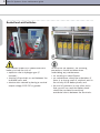
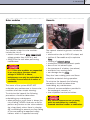
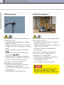
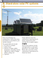
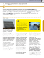
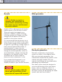
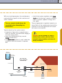
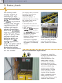
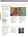
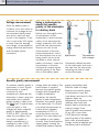
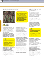
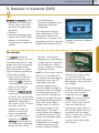
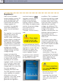
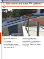
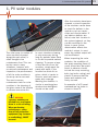
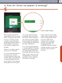
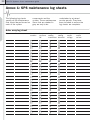
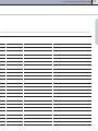
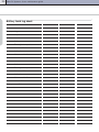
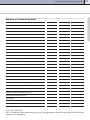
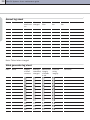
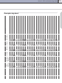
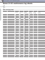
Solar PV systems
Users’ maintenance guide
Solar PV Systems: Users maintenance guide
Produced by
Australian Business Council
for Sustainable Energy
60 Leicester Street
Carlton Victoria 3053
Australia
Phone: 03 9349 3077
Website: www.bcse.org.au
Funded by
Australian Greenhouse
Office
Major contributors
Jeff Hoy, JP Energy
Technologies
Brad Shone, Alternative
Technology Association
(ATA)
Geoff Stapleton, Global
Sustainable Energy
Solutions
Mike Russell, Business
Council for Sustainable
Energy
Nigel Wilmot, Research
Institute for Sustainable
Energy (RISE)
ISBN: 978-0-9802806-9-2
The information in this guide
has been provided as a
guide to solar PV systems.
While every effort has been
made to ensure the content
is useful and relevant, no
responsibility for any
purchasing decision based
on this information is
accepted by the Australian
Business Council for
Sustainable Energy or other
contributors.
Australian Government
funding through the
Australian Greenhouse
Office in the Department of
the Environment and Water
Resources supports this
project.
The views expressed herein
are not necessarily the
views of the Commonwealth,
and the Commonwealth
does not accept
responsibility for any
information or advice
contained herein.
Solar PV Systems: Users maintenance guide
Contents
A: Introduction
1. About this guide
Maintenance
2. Precautions and warnings
3
3
3
4
B: Stand-alone solar
PV systems
1. Energy generation equipment
10
11
Solar array
11
Gensets
12
12
240 volt output
4
Wind generators
Battery banks
5
Pico-hydro generators
Wet lead-acid batteries
5
Sealed lead acid batteries
6
General installation requirements
Solar modules
7
Safety first!
15
Gensets
7
Maintenance of battery banks
16
Wind generators
8
Checking your batteries
16
Pico-hydro generators
8
Charging your batteries
17
3. Maintenance schedules and logbooks 9
2. Battery bank
12
14
14
Checking the voltage
17
Typical battery maintenance tasks
18
Isolating the system for maintenance
18
Cleaning the cells
19
Checking the charge and condition
of the battery bank
19
Voltage measurement
20
Specific gravity measurement
20
Using a hydrometer
20
Neutralising acid spills
21
Topping up the electrolyte
21
Cleaning the battery terminals
22
Differences for gel cell type batteries
22
1
2
Solar PV Systems: Users maintenance guide
3. Balance of Systems (BOS)
The inverter
23
Annex 1: SPS maintenance
log sheets
32
Regulator(s)
24
Switchboards and wiring
25
Solar array log sheet
32
Battery chargers
25
Battery bank log sheet
34
System wiring
25
Balance of systems log sheet
35
Genset log sheet
36
4. Interpretation of monitoring
equipment
26
Solar array meter
26
Wind generator meter
26
Pico-hydro meter
26
System voltage meter
27
Other monitoring
27
C: Grid-connected solar
PV systems
1.
2.
3.
4.
23
PV solar modules
Inverters
Balance of system
How do I know my system is working?
28
29
30
30
31
Wind generator log sheet
36
Pico-hydro log sheet
37
Annex 2: GC maintenance
log sheets
Solar array log sheet
38
38
Inverter log sheet
40
BOS log sheet
40
Annex 3: Glossary
41
Annex 4: SPS maintenance
at a glance
43
Safety First
Annex 5: Information to be
obtained from System
Supplier or Manufacturers
43
44
A: Introduction
A: Introduction
1. About this guide
This guide will give you an overview of the
maintenance required for a typical stand-alone
solar power system (SPS)* and grid-connected
solar power system (GC) including precautions
and warnings on the hazards of working with
solar power systems.
SPS maintenance is covered
in Section B and GC in
Section C.
For each section:
• the first three chapters
provide an overview of
each of the individual
components followed by a
more detailed description
of the maintenance
required;
• the final chapter describes
how to monitor the
operation of the system.
Annexes 1 and 2
demonstrate sample log
sheets for a system
l o g b o o k.
Annex 3 is the glossary of
terms introduced in this
guide.
Annex 4 is an at-a-glance
sheet.
Annex 5 is information to
check with system supplier
or manufacturer
Maintenance
* A definition of all words or
phrases in bold italics is
provided in Annex 3, the
glossary
As with any piece of
equipment, performing
regular maintenance and
inspection of components
will help ensure system
performance and minimise
disruption due to component
failure. If our described
procedures differ from those
suggested by your
manufacturer and/or
installer, follow the
procedures outlined in the
system user manual
supplied with your system.
This guide is designed for
those already familiar with
the basic components and
configuration of solar power
systems. More introductory
information can be found in
the Electricity From The Sun
– Solar PV Systems
Explained (ISBN: 978-09802806-7-8) available from
your installer. There are
many books available to
provide further details about
these systems and
components.
As part of the regular
maintenance of a system, it
is recommended that you
keep a logbook recording all
system maintenance and
performance. In the logbook
the type and frequency of
maintenance and who
performed it should be
recorded. If kept up to date,
it can be used to provide a
history of the system which
can then be used for fault
diagnosis. With some standalone systems, a logbook is
required to be kept in
accordance with the battery
warranty conditions. Check
with the system supplier
concerning any logbook
requirements.
3
4
Solar PV Systems: Users maintenance guide
2. Precautions and warnings
Solar power systems
are safe when
operating correctly
however there are
potentially dangerous
hazards associated
with some system
components.
These hazards can include:
• 240V outputs and other
dangerous voltages;
• batteries;
• solar modules;
• gensets ;
• wind generators; and
• p i c o - h y d r o generators .
240 volt output
Safety warnings
The following symbols
appear in this manual.
Immediate SAFETY
Hazard
Failure to follow
recommended
procedure will result in
serious injury.
General SAFETY
Warning
Failure to follow
recommended
procedure could result
in injury.
A stand-alone power system
(SPS) typically provides
240V AC power without
being connected to the
electricity grid.
Electrical SAFETY
Warning
Failure to follow
recommended
procedure could result
in injury.
Work Safely
Wear protective eyewear
and appropriate clothing
during maintenance.
A grid-connected power
system (GC) provides 240V
AC power by being
connected to the electricity
grid, often referred to as
power lines or mains power.
A: Introduction
Battery banks
Although 240V AC power is
dangerous and can cause
death when live exposed
wires/terminals are touched
or cause fire, it is generally
safe when kept in good
working order.
Low voltage (LV) is specified
in the Australian Standards
as any voltage equal to or
higher than 50V AC or 120V
DC. Any service requiring LV
wiring must be undertaken
by a suitably licensed
electrical worker or
contractor. The owner of the
system MUST NOT
undertake any maintenance
to LV wiring systems or the
output terminals of
equipment that produces low
voltage (LV).
NOTE If the battery bank
has a nominal voltage of
120V DC or above,
maintenance can only be
undertaken by a suitably
licensed electrical
worker or contractor.
The owner of the system
MUST NOT undertake any
maintenance to battery
banks 120V DC or above.
The battery bank can include
either wet lead-acid or
sealed lead-acid cells.
Wet lead-acid batteries
The hazards related to a wet
lead-acid battery bank
include the risk of:
• explosion due to hydr ogen
gas;
• burns caused by acid in
the individual cells;
• shor t i n g of ter minals on
and between the individual
cells; and
• electrocution caused by an
output voltage 120V DC or
greater.
To minimise the hazards the
following precautions should
be taken when undertaking
any maintenance:
• no maintenance should be
undertaken if there is a
strong smell of sulphuric
acid in the vicinity of the
battery bank;
• no smoking or naked
flames;
• safety goggles MUST be
worn;
• acid resistant gloves
MUST be worn;
• acid resistant apron or
clothing should also be
worn;
• clean water should be
available near the
batteries to wash any acid
that comes in contact with
skin;
• bi-carbonate soda should
also be available to be
used, with water, to
neutralise any acid that is
spilled onto the ground;
and
• the end of spanners (or
any other tools) that you
will use near the battery
bank should be insulated
to avoid any accidental
shorts between the
terminals.
5
6
Solar PV Systems: Users maintenance guide
Sealed lead acid batteries
The hazards related to a sealed lead acid
battery include the risk of:
• explosion due to hydrogen gas (if
covered);
• shorting of terminals on and between the
individual cells; and
• electrocution caused by having a nominal
output voltage 120V DC or greater.
To minimise the hazards, the following
precautions should be taken when
undertaking any maintenance:
• no smoking or naked flames
• no maintenance should be undertaken if
there is a strong smell of sulphuric acid in
the vicinity of the battery bank; and
• the end of spanners (or any other tools)
that you will use near the battery bank
should be insulated to avoid any
accidental shorts between the terminals.
A: Introduction
Solar modules
Gensets
The hazards related to solar modules
include the risk of:
• electric shock due to array open-cir c u i t
voltage greater than 120V d.c; and
• falling from the roof when performing
maintenance.
The hazards related to gensets include the
risk of:
• electrocution due to 240V AC output; and
• ignition of flammable and/or explosive
fuels
• inhaling of exhaust gases
• combustion caused by exhaust sparks
• burns from hot exhaust pipe
• the presence of a battery (see above)
• accidents from moving parts
• ear damage due to noise.
NOTE If the solar modules are connected
in an array where the open circuit
voltage is 120V DC or above,
maintenance can only be undertaken by
a suitably licensed electrical worker or
contractor.
The owner of the system MUST NOT
undertake any maintenance to these solar
modules other than simple cleaning.
To minimise the hazards the following
precautions should be taken when
undertaking any maintenance:
• when working on roofs there is always the
risk of falling. NEVER climb onto a roof to
perform any service on the solar modules
(eg. clean them) unless there is a barrier
(eg. scaffolding) to prevent you from falling
or you are wearing an approved safety
harness which is supported correctly.
They also have rotating parts and these
should be protected during operation.
To minimise the hazards the following
precautions should be taken when
undertaking any maintenance:
• follow all recommendations provided in
the equipment manuals; or
• use a qualified service technician.
Any service required to the LV wiring
must be undertaken by a suitably
licensed electrical worker or contractor.
7
8
Solar PV Systems: Users maintenance guide
Wind generators
Pico-hydro generators
The hazards related to wind generators can
include the risk of:
• electrocution due to dangerous voltages
(either DC or AC LV) ;
• falling from the top of a pole or structure;
• damage caused by rotating and/or moving
parts.
• an accident while lowering or raising of
tower
• damage by stumbling into unfenced or
unprotected guy wir es
• being hit by tail in sudden wind gusts (if
structure tower is suitable for climbing).
The hazards related to pico-hydro generators
can include the risk of:
• electrocution due to dangerous voltages
(either DC or AC LV) ;
• falling whilst accessing pipes in steep and
slippery locations; and
• accidents caused by rotating and/or
moving parts.
To minimise the hazards the following
precautions should be taken when
undertaking any maintenance:
• follow all recommendations provided in
the equipment manuals; and
• use a brake on turbine before lowering or
raising tower; or
• use a qualified service technician.
To minimise the hazards, the following
precautions should be taken when
undertaking any maintenance:
• follow all recommendations provided in
the equipment manuals; and
• turn off water source or
• use a qualified service technician.
Any service required to the LV wiring
must be undertaken by a suitably
licensed electrical worker or contractor.
A: Introduction
3. Maintenance schedules and logbooks
A maintenance schedule with an
equipment logbook (or logbooks)
should be provided as part of the
documentation supplied to the
system owner by the supplier at the
completion of system installation
and commissioning.
Suggested maintenance intervals and
records for major equipment components of
an SPS or GC system are provided in
sections B and C.
A loose-leaf folder can be used as the
system log book with individual sheets
added for each item.
Though having one folder might be ideal for
an SPS, often you will have a couple of
logbooks due to gensets requiring regular
services like a car and can be supplied with
their own logbook. Battery bank
manufacturers can often supply battery
logbooks, which must be completed to meet
warranty conditions.
If you do have separate logbooks, it is
advisable to keep them together in a clean
dry location.
Annex 1 (SPS) and Annex 2 (GC) provide
examples of sheets that can be used for
each piece of equipment. When completing
the log sheets, the date and name of
person undertaking the maintenance or
inspection should be recorded.
Log books can be particularly useful
because the historical information they
contain can show changes over time, as
well as abnormal variations from the usual,
indicating a problem, or a potential problem.
9
10
Solar PV Systems: Users maintenance guide
B: Stand-alone solar PV systems
Prior to performing any
maintenance, follow shut down
procedures as specified in your
system manual.
The typical SPS will include:
• PV array of modules;
• battery bank;
• balance of system (BOS)
equipment—including inverter,
regulator(s), battery charger,
system wiring; and
• a genset.
These sections cover the
maintenance requirements for
these components which
includes the complete system
i n t e g r i t y.
Since some systems include
wind generators or pico-hydro
generators, this chapter does
finish with a summary of the
maintenance requirements for
these two items.
B: Stand-alone solar PV systems
1. Energy generation equipment
Energy generation equipment includes the solar photovoltaic array,
gensets, wind generators, pico-hydro generators and is also considered to
include associated equipment such as frames, trackers, towers, water
pipes and regulators or controllers. The regulators and controllers are
discussed in chapter B3.
Solar array
WARNING If modules are
The solar array (a number of
solar modules mounted
together) is quite often
referred to as being
maintenance free. This can
be the case in many
situations, however, with
occasional maintenance and
inspection, the performance
of all the solar modules in
the array can be assured.
The most common
maintenance task for solar
modules is the cleaning of
the glass area to remove
excessive dirt.
An example of a PV panel
maintenance log sheet is
shown in Annex 2.
located on the roof and
there is a risk of falling
during maintenance, then
fall protection equipment
(eg. harness or
scaffolding) MUST be
used.
In most situations cleaning
is only necessary during
long dry periods when there
is no rain to provide natural
cleaning. To remove a layer
of dust and dirt from the
modules, simply wash the
module with water. If the
module has thick dirt or
grime, which is harder to
remove, wash with warm
water and a sponge.
Washing the modules is
similar to washing glass
windows but detergents
should not be used. The
modules should be cleaned
when they are not
excessively hot, typically
early in the morning.
After the modules have been
cleaned, a visual inspection
of the modules can be done
to check for defects such as
cracks, chips and
discolouration. If any obvious
defects are found, note their
location in the system
logbook, so these can be
monitored in the future in
case further deterioration
affects the modules’ output.
When inspecting the solar
modules, the condition of
the array mounting frame
should also be noted. Items
to observe should include
the array mounting bolts (eg.
bolts rusting) and checks to
ensure that the frame and
modules are firmly secured.
11
12
Solar PV Systems: Users maintenance guide
Gensets
Wind generators
WARNING Disable any remote or
automatic start mechanisms for
gensets before commencing servicing.
Also remove any keys and disconnect
any starter batteries.
A petrol, LPG or diesel genset will require
regular checks of the fuel and oil levels.
These will need to be topped up as
required. In addition, regular servicing
including complete oil changes and filter
changes will be required, at intervals
specified in the system manual.
It is recommended that all gensets do at
least have an AC volt meter on the output
so the output voltage can be monitored. If
the genset is generating a voltage higher or
lower than the typical 240V (230V), or
operating faster or slower than the
recommended speed, the genset could
damage household appliances while the
associated battery charger could also be
damaged or not operate correctly. There
should also be a run-hour meter to
determine when maintenance is due.
If you suspect that the genset is not
operating correctly, call your system
supplier/installer or your service mechanic.
WARNING Gensets produce 240V AC.
Do not open any enclosures on the
genset that will expose LIVE terminals.
Pico-hydro generators
The basic components of a pico-hydro
system are shown in the diagram below.
With most pico-hydro generators, the
maintenance required will be specific to the
machine and pipe installed. The user
manual should always be consulted before
attempting any maintenance.
The intake system should be designed to
minimise the blocking of the inlet pipe by
leaves, sticks or silting up. If this is a
problem then the main maintenance on a
pico-hydro system will be keeping the intake
system clean and free of debris.
B: Stand-alone solar PV systems
With most wind generators the maintenance
required will be specific to the machine and
tower installed.
• check that system regulators and dump
loads are functioning in windy conditions,
(refer to system supplier if things don’t
look right).
The wind generator is typically located on a
tower. Most of the maintenance that will be
required on the wind generator will require
the tower to be lowered.
The user manual should always be
consulted before attempting any
maintenance.
Typical checks by the system owner:
• inspection of guy wires on guyed tower—
check for tension, and excessive fraying or
corrosion of guy wires;
• check the functioning of any manual
furling mechanisms;
• if a cable twist system is used, check the
amount of twist and untwist if required;
and
WARNING Do not attempt to lower a
turbine tower unless you have been
trained in this procedure and never in
windy conditions.
W AT E R
STORAGE
I N TA K E
SYSTEM
The water flow
can be controlled
automatically
PIPELINE
CONTROLS
To Load
I S O L AT I N G
VA LV E
G E N E R AT O R
To stream
TURBINE
SHUNT
LOADS
13
14
Solar PV Systems: Users maintenance guide
2. Battery bank
The battery bank
usually consists of
individual 2V cells
connected together in
series and sometimes
in parallel to provide a
battery bank with the
required system DC
voltage and energy
storage. Sometimes
12V or 6V monoblock
cells are used instead
of the 2V cells. These
systems should use
batteries which are
designed for deep
cycling applications
which are better suited
to the charging and
discharging regime.
Car and truck batteries
are not suitable.
The battery bank should be
housed in an enclosure
accessible only to
authorised people. An
authorised person could be
the system owner or an
appointed person.
In Australia there are two
main types of batteries used
in SPS systems:
• Wet cell flooded batteries
(vented cells)—in which
the electr olyte level must
be regularly checked.
• Sealed or gel cell
batteries—where there is
no access to the
electrolyte, a regulated
valve is incorporated and
the battery is completely
sealed.
Nickel cadmium (NiCad) and
nickel iron (NiFe) batteries
are rarely used for solar
power systems in Australia.
General installation requirements
The batteries should be
located in accordance with
manufacturer’s
recommendations. The
battery bank must be
protected by a suitable
enclosure which is only
accessible by appropriately
authorised people (eg.
system owner, installer,
service person). In large
sheds the battery bank
should still be housed in
either a separate room or
battery box to prevent
unauthorised access and to
separate spark sources
B: Stand-alone solar PV systems
Safety first!
Always remember that a
battery is a form of energy
storage which, under certain
conditions, can release its
energy instantaneously, with
explosive consequences.
The battery bank should only
be accessible to people who
understand its functioning
and are responsible for its
maintenance. It should be
able to restrict access to
other people, especially
children. As far as possible,
the area should be animal
and vermin proof. Restricting
access to the batteries will
be the first and often the
from explosive vented
battery gases. All battery
installations should be
either naturally or for ced
ventilated to prevent the
build up of explosive gases.
The battery enclosure
should be clean, dry and
lockable to prevent
unauthorised access. It
should also house only the
batteries.
Good access to the battery
terminals and electrolyte
filler caps is required.
Generally, batteries are
best safety measure.
Suitable safety signs should
caution people of the
dangers (see example
signage above.)
The following safety
equipment should always be
available and ready to use.
People who have access to
the battery bank area should
all be instructed in its use.
• Bucket of clean water –for
rinsing off acid splashes.
installed on a battery rack or
on timber to keep them off
the floor and provide the
required access to the
batteries. There should not
be shelves or any other
equipment above the
batteries because items
falling from these shelves
onto the batteries could
cause a short circuit or the
equipment itself could be
spark generating. In addition,
gases from the battery can
corrode equipment. Avoid
clutter around the battery
enclosure to facilitate easy
• Safety goggles or face
shield – for face and eye
protection.
• Rubber gloves – for
protection of hands.
• Eyewash bottle – for
rinsing acid splashes out
of eyes.
• Overalls or apron – for
protection of body and
clothing from acid splash.
• Baking soda (Bicarbonate)
– for neutralising acid
spills.
access. The battery
enclosure must not be used
as a storage area.
Minimise the battery bank’s
exposure to extremes of
temperature because this
can reduce performance and
life. The battery bank should
be installed so that each
individual battery is exposed
to the same temperature
conditions. Provision should
be made for the
containment of any spilled
electrolyte.
15
16
Solar PV Systems: Users maintenance guide
Maintenance of battery banks
Generally maintenance of
batteries will concentrate on
correct charging regimes,
electrolyte condition, battery
terminals and overall battery
safety.
Before you start
Before you start with your
maintenance, ensure all
safety equipment is at hand
and ready to use. Listed
below is typical equipment
you will need for these
maintenance tasks safely
and correctly.
Safety equipment
See safety first! above
• Hydr ometer – for checking
specific gravity of
electrolyte and hence
battery charge.
• Glass bulb type
thermometer – for
temperature measurement
of electrolyte.
• Container with clean water
to rinse hydrometer and
thermometer.
• Handheld voltmeter or
multimeter – for checking
battery voltage.
• Appropriate tools – correct
size spanners and/or
screwdrivers with
insulated handles.
Checking your batteries
As part of regular
maintenance, a thorough
visual inspection of the
battery bank is required.
This inspection should
include:
• cleanliness of batteries;
• level of electrolyte, (not
required for gel cell
batteries);
• condition of battery
terminals;
• signs of any electrolyte in
the safety trays (if
provided) or on the floor,
indicating a possible
battery leak or overfilling;
• condition of battery
containers; and
• battery voltage level.
• Plastic type dishwashing
scourer or similar – for
cleaning battery terminals
and connectors.
• Anti oxidant coating – for
coating battery terminals
and connectors after
cleaning.
• Baking soda – for cleaning
of batteries.
B: Stand-alone solar PV systems
Charging your batteries
To maximise the life of a
battery bank, it is best to
ensure that it is regularly
receiving a full charge and
that its state of charge is
not allowed to fall
excessively. Please check
the manufacturer’s
recommendation with the
system supplier—some
solar lead acid batteries can
go down to a maximum
depth of dischar ge of 7080% while, for some deep
cycle lead acid batteries, the
recommended maximum
depth of discharge is 50%.
Each day, at around the
same time, the battery
voltage should be checked,
as this will give you a regular
indication of the battery
charge condition. Decisions
on energy use can be made
based on this check to avoid
over discharge of the battery.
Such decisions may include
delaying energy use or using
backup generators to charge
the batteries. When you
become more familiar with
the operation of your system,
this battery check may occur
less frequently.
For flooded batteries, the
battery bank also requires
an equalisation charge to
ensure that all individual
cells in the bank are at a
similar charge. This is
achieved by charging the
battery until bubbling
(gassing) occurs. The period
between equalisation
charges is dependent upon
manufacturer and typically
vary from 7–28 days but
some batteries can be as
high as 90 days. Please
check with your system
supplier. If the equalisation
charge is not achieved by
the solar array then the
genset will need to be run
and the charging provided by
the separate battery
charger.
Checking the voltage
The table below lists typical
voltage levels that indicate
whether the state of charge
is good or bad for the
battery bank. This table is
valid when the batteries are
at rest, (ie. no charge or
discharge is occurring). This
table should only be used as
Nominal
Voltage
2V
12V
24V
48V
Bad
<1.9
<11.4
<22.8
<45.6
a guide and for accurate
charge levels the specific
gravity of each cell should
be tested, where possible.
The table below is typical of
flooded wet cell batteries at
25oC. At higher or lower
temperatures, correction
should be made using
temperature correction
factors from your battery
specifications. If you have
gel cell batteries, you can
only check the battery
specifications from the
manufacturer for an
indication of state of charge
for various voltage levels.
Time to start
economising or using
backup charger
Good
1.9-2.0
11.4-12
22.8-24
45.6-48
2-2.2
12-13.2
24-26.4
48-52.8
Caution
(depending
on battery –
see note)
>2.4
>14.4
>28.8
>57.6
Note: Some batteries have an equalisation or boost charge of 2.6V per 2V cell.
17
18
Solar PV Systems: Users maintenance guide
Typical battery maintenance tasks
Preparing the system for
battery maintenance
It is important to avoid clutter
around the battery bank, so
remove all unnecessary
items, leaving only safety
gear and equipment required
for the maintenance of the
battery bank.
Before starting the battery
bank maintenance, it is
extremely important to
isolate the battery bank
from the system to shut the
system down.
Follow the specified
shutdown procedure—you
should see a sign on the
wall near your equipment,
spelling out this procedure.
The user manual may
provide further information.
It is also best to wait for the
solar regulator, wind
generator dump load or picohydro dump load to have
finished a boost char ge
before switching to a float
char ge mode.
Ensure there is plenty of
ventilation in the battery
enclosure or room. If using
forced ventilation, check that
ventilation systems are
functioning correctly and are
clean and unobstructed.
For consistency in the
recording of specific gravity
and voltage measurements,
each cell should have a
permanent number
identification on it which is
not easily erased by wear
and maintenance. When
recording specific gravity or
voltage, these numbers can
be used as a reference
label.
Before assessing the
condition of a battery, it is
best to have a fully charged
battery.
Isolating the system for maintenance
A typical process in shutting
down a system and isolating
the battery bank to make it
safe to perform the
maintenance tasks would
follow the following steps.
WARNING Refer to
system user manual
provided by system
supplier for exact
procedures relevant to
your system.
1. Shut down (turn off) all
loads on the system
starting from the
household appliances
and working back to the
inverter.
2. Disconnect (turn off) all
energy generation devices
such as solar or wind
generators.
3. Shut down the battery
bank—this would involve
either switching off
cir cuit br eakers or
removing any fuses on
the battery bank. If fuses
are used, the fuse on the
negative terminal of the
battery bank should be
removed first followed by
the fuse on the positive
terminal.
4. If a switch-fuse is used,
opening the switch fuse
disconnects the fuses
from the batteries.
Remove the front
mechanism to prevent it
being closed while you
are working.
5. When a circuit breaker is
used, either place a ‘Do
B: Stand-alone solar PV systems
Cleaning the cells
Each cell should be clean
before removing any filler
caps to perform
maintenance or
measurements. This will
avoid contamination of the
cell by dirt. To clean the
cells, use either a brush to
remove dry material and/or
a rag dipped in a solution of
baking soda and water and
thoroughly squeezed out.
Checking the charge
and condition of the
battery bank
WARNING When
cleaning batteries,
avoid using excess
water which may spill
into the cell and always
wipe away from
electrolyte filler holes.
Do not allow any baking
soda to enter the cell—
even a tiny amount of
baking soda will
permanently damage
the cell.
There are two methods for
determining the state of
charge and condition of the
battery bank. They are:
• measuring the voltage of
each cell;
• measuring the specific
gravity of the electrolyte in
each cell.
The measuring of specific
gravity is the more accurate
measure of a cell’s state of
charge when used in conjunction with manufacturer’s
specifications and data.
Frequent recording of the
specific gravity of your cells
can be part of their warranty
requirements.
have its own circuit
breakers or switch-fuses,
to isolate each parallel
string, as described
above.
not operate tag’ on the
circuit breaker or
physically isolate the
battery bank by removing
the battery cabling, first
from the negative
terminal, then from the
positive terminal.
6. If the battery bank
contains more than one
string of cells, each
parallel string should
The battery bank is now
electrically isolated from all
energy generating devices
and loads. It can now be
worked on for maintenance
BUT remember each cell is
an energy storage deviceshorting of any terminals is
dangerous and can cause an
explosion.
19
20
Solar PV Systems: Users maintenance guide
Voltage measurement
Once the battery bank is
isolated, use a volt meter to
measure the voltage across
the complete battery bank
and across each cell and
record in the logbook. If any
cell is more than 10% higher
or lower than the average
cell voltage, an equalisation
charge should be performed
and the battery bank
rechecked.
Using a hydrometer to
check the specific
gravity of the electrolyte
in a battery bank
Before use, thoroughly rinse
all components of the
hydrometer to avoid contamination of the electrolyte by
foreign materials. Also rinse
and clean the thermometer.
Choose one cell for the
measurement of the electrolyte temperature. Insert
the thermometer into a cell,
being careful not to touch
any plate or other internal
battery structures. Leave the
thermometer in the electrolyte while measuring the
specific gravity of the other
cells in the battery bank.
Hydrometer
Thermometer
with stopper
Completely deflate the bulb
of the hydrometer and insert
the tube into the electrolyte,
releasing the bulb to draw
up the electrolyte.
Specific gravity measurement
To measure specific gravity, a
hydrometer is used. A glass
thermometer is used to
measure the cells’
temperatures. Generally the
electrolyte is drawn up by the
hydrometer and a specific
gravity reading is taken from
the float level. A typical deep
cycle cell which is fully
charged will have a specific
gravity of approximately
1.250 at 25°C. (Confirm the
value for your battery from
the system supplier or
battery manufacturer). A
reading less than 1.250
indicates a lower state of
charge within the battery. The
thermometer is required
because the specific gravity
changes with temperature.
A higher temperature
decreases the specific
gravity; a lower temperature
increases the specific gravity
of the electrolyte. To convert
your actual measurement to
a value at the standard
temperature of 25°C, a
correction factor must be
applied. This information will
be supplied in your battery
manual. Some manufacturers
supply graphs showing the
relationship between specific
gravity, temperature and
effective state of charge
Measure the specific gravity
of electrolyte in each cell,
(see above) and record in the
logbook. Apply the
temperature correction to the
readings and check with
battery data to estimate the
state of charge. If the
specific gravity measurement
of any cell is more than
0.025 below the average
specific gravity of the battery
bank, then an equalisation
charge should be applied and
the battery bank rechecked.
B: Stand-alone solar PV systems
WARNING Use only
distilled water for rinsing
hydrometer and thermometer. Use of bore water
may introduce
contaminants which are
damaging to batteries.
Reading the electrolyte
specific gravity
Squeeze the bulb and
deflate, squirting electrolyte
carefully back into cell.
Repeat this three to four
times to ensure that the
hydrometer is at the same
temperature as the
electrolyte.
Now fill the hydrometer and
hold it vertically, ensuring its
float is floating in the
electrolyte. Now read the
electrolyte level off the float.
Return the electrolyte to the
cell. Record the reading in
the logbook. Rinse the
hydrometer in fresh water
and test the next cell,
following the same procedure
until all cells are tested.
Neutralising acid spills
Topping up the electrolyte
To neutralise an acid spill, use a solution of
baking soda and water. Mix half a cup of
baking soda in approximately 10 litres of
water. For larger spills, use a mop to clean
up the spill. This solution can also be used
for cleaning the cells and battery terminals.
When batteries are charging and gassing,
the battery is losing water. To top up the
electrolyte, use distilled water (or de-ionised
water) and fill the battery via the electrolyte
filler hole until the correct level is reached.
There are several types of indicators to show
the level is correct. These indicators vary
from simple markings on the side of the
battery case, indicating high and low levels
to systems which use a float indicator.
WARNING When neutralising acid spills
do not allow any baking soda solution
to enter the battery cells—even a tiny
amount of baking soda will
permanently damage the cell.
Check the manufacturer’s instructions for
the type of indicator used in your batteries.
It is preferable to add distilled water when
the battery charge is high as the addition of
water will decrease the charge of the
battery.
21
22
Solar PV Systems: Users maintenance guide
Cleaning the battery terminals
WARNING Do not use
any metal files or other
harsh abrasives (eg.
sand paper) to remove
corrosion or oxidisation
from terminals or posts
as this may cause a
poor fit when terminals
are reconnected.
If the battery terminals are
showing signs of corrosion,
or have not had an antioxidising coating applied,
they may require cleaning.
This will involve
disconnecting the battery
leads and cleaning both the
battery terminal posts and
the battery lead connectors.
It is important to ensure
the battery bank has
been isolated before
attempting to
disconnect any leads.
Battery terminal corrosion is
often seen as a white
crystalline or powdery
material around or on the
battery terminals. A heavily
oxidised terminal will have a
very dark, almost black
coating. If this is between
mating surfaces of the
connectors and posts it will
need to be cleaned.
Before disconnecting,
carefully wipe most of the
corrosion off using a brush
or rag with the baking soda
solution, then carefully
disconnect the battery lead
connector from the battery
terminal post and clean both
using a plastic scourer.
Once clean, apply the antioxidising coating following
the manufacturer’s
recommended procedure
and reconnect the battery
lead connector onto the
battery terminal post.
Repeat this procedure for
each terminal, as required,
being careful not to
contaminate the electrolyte
with any foreign material.
Differences for gel cell
type batteries
Gel cell batteries require
special attention to the
method used for charging as
overcharging of a gel cell
type battery may cause
irreversible damage to the
battery. Consult with system
supplier for
recommendations on
charging of gel cell type
batteries. Controllers and
chargers should be set to
the gel cell mode for best
performance.
NOTE Overcharging a gel
battery can lead to
battery gases escaping
with a similar risk of
explosion as for wet
lead-acid batteries.
Maintenance of gel cell
batteries only relates to the
battery terminals and
connections. The
maintenance required for
these is the same as for wet
cell flooded batteries.
The state of charge of the
battery can only be
determined by measuring
voltage of the battery, when
there has been no
discharging or charging of
the battery for at least 1530 minutes, and referring to
tables supplied by the
manufacturer.
B: Stand-alone solar PV systems
3. Balance of systems (BOS)
Balance of systems include:
• regulators (or controllers)
for the solar array, wind
generator and pico-hydro
generator;
• inverters;
• all interconnecting power
cables and control cables
between the individual
components to create the
system;
• all switchboards,
protection equipment and
metering/monitoring
equipment.
This equipment requires
little maintenance. If this
equipment requires any
maintenance or repair it will
generally need to be done by
qualified personnel and the
supplier should be contacted
for advice.
The inverter
The inver ter should be
installed in a clean, dry, and
ventilated area which is separated from, and not directly
above, the battery bank.
While the system is operating the following operational
checks can be made:
• check that the inverter is
functioning correctly by
observing LED indicators,
metering and/or other displays on the inverter
• check to see if the
inverter’s stand-by mode
(if present) is functioning
correctly. This can be done
by turning off all loads and
appliances operating on
the system. Once in standby mode, switch an
appliance on and the
inverter should start
almost immediately.
• check that any control
functions for r emote
star ting of diesel genset
(if installed) are operating.
Ensure that the diesel
genset is starting and
stopping at correct battery
voltage levels as specified
by manufacturer (refer to
system supplier or inverter
operating manual).
NOTE The third check can be
difficult to undertake as it
can require disconnecting all
charging sources (eg. PV
array) and turning on
sufficient appliances to
force the battery voltage to
decrease to the set voltage
for starting the genset. It
could also be simulated by
raising the voltage setting so
checking that the generator
does start at the higher
voltage, which is close to
the actual voltage of the
battery bank. The exact
testing method will depend
on the actual set-up of the
system and probably might
only be able to be
undertaken by a suitably
qualified person eg. the
system supplier/installer.
Typically the system owner
is only aware that the
genset has not started when
the batteries have reached a
low voltage.
When inspecting the
inverter, remove any excess
dust from the unit and
especially from the heatsinks. This should only be
done with a dry cloth or
brush. Check that “vermin”
have not infested the
inverter eg. typical signs of
this include spider webs on
ventilation grills or wasps’
nests in heat sinks. Contact
system suppliers if you
suspect vermin are inside
the inverter.
23
24
Solar PV Systems: Users maintenance guide
Regulator(s)
Each of the renewable
energy charging sources: PV
array, wind generator and
pico-hydro generator will
require their own specific
charge regulator (or
controller). Any regulator
should be installed in a
clean, dry and ventilated
area.
The regulator is an electronic
device that controls the
voltage of the charging
sources (solar, wind, hydro)
energy output to charge the
battery bank appropriately.
The regulators are designed
to disconnect or reduce the
charge current when preset
voltages are reached.
Typically there are boost
voltage settings and float
voltage settings.
Inspect and check the
functioning of the regulator
to ensure that any indicators
or meters are correctly
operating for the various
regulator modes. In the case
of a PV system, check that
when the batteries are fully
charged and it is sunny, that
the solar regulator is
changing into float mode.
The wind generator and picohydro regulator do operate
differently to the solar
regulator. If you have a wind
generator or pico-hydro
generator the regulators
used are known as shunt
regulators and will require
additional components
known as dummy loads,
typically a bank of resistive
coils. When the battery bank
reaches the preset voltage,
the current from the
generator source is
“shunted” into the dummy
load.
WARNING These shunts
can get very hot and
should not be touched.
During maintenance checks,
inspect the functioning of the
regulator to ensure that any
indicators or meters are
correctly operating for the
various regulator modes.
In general correct operation
of the regulator(s) can only
be observed in certain
conditions. This is achieved
by observing that the charge
currents from the different
sources (solar, wind or picohydro) are either removed or
reduced when specified
voltages are obtained. This
could be observed when the
voltage of the battery
reaches a certain point, this
indicates that the battery is
fully charged and the
regulators go from boost to
float mode.
Full operation tests might
need to be undertaken by a
suitably qualified person eg.
the system supplier/installer.
When inspecting the
regulators:
• look for any loose wiring
on the terminal
connections. If they are
loose follow the shutdown
procedures for the system
before tightening the
connections or contact
your installer.
NOTE Loose connections
can cause hot joints and
possibly fire.
• remove any excess dust
from the unit and
especially from the heatsinks. This should only be
done with a dry cloth or
brush.
B: Stand-alone solar PV systems
Switchboards and wiring
Correctly installed switchboards and wiring should not
require maintenance.
The licensed electrical
contractor who installed the
system should have checked
all existing wiring and
switchboards.
As part of your system
inspection, the switchboards
and visible wiring can be
visually inspected for signs
of corrosion and/or burning.
If either is apparent, consult
a licensed electrical
contractor to identify and
rectify possible faults.
All safety switches, r esidual
c u r r ent devices (RCDs)
which detect current leakage
to earth should be tested by
pressing the test button
provided.
Residual current device
(RCD)
Battery chargers
The maintenance required for
battery charging equipment
is similar to that required for
inverters.
Check that the charger does
charge the battery bank
when the genset is
operating. If it does not
appear to be operating
correctly check the output
voltage of the genset. (if volt
meter has been installed). If
genset is not producing
correct output voltage, then
the battery charger will not
operate correctly. If the
genset is OK then contact
system supplier/installer.
Any battery charging equipment should be installed in a
System wiring
Check for any breaks or
deterioration in exposed
conduit and wiring. Also
inspect connections for any
signs of corrosion and/or
burning. If any damage is
noticed contact the system
supplier/installer.
Inspect the condition of the
conduit and wiring from the:
• charging source to its
regulator;
•
•
•
•
regulator to battery bank;
inverter to battery bank;
genset to battery charger
battery charger to battery
bank
• inverter and genset to AC
switchboard.
An example of poorly wired,
unprotected and
unsupported cabling for
a charger
clean, dry and ventilated
area.
When inspecting the charging equipment remove any
excess dust from the unit
and especially from any heatsinks. This should only be
done with a dry cloth or
brush.
25
26
Solar PV Systems: Users maintenance guide
4.
Interpretation of monitoring equipment
Often a system owner
is unaware of a
problem until suddenly
the inverter turns off
and the house has no
power. Typically the
system will include a
back-up genset so that
this can be operated to
provide power to the
house but this will be
noisy, expensive,
environmentally
unfriendly and
inconvenient.
As a minimum, the
Australian Standard
recommends that your
system should include a volt
meter for measuring the
system DC voltage and a
current meter from each of
the charging sources (solar,
wind and/or pico-hydro).
Regularly monitoring these
meters will help to identify a
problem before the point is
reached where the inverter
switches off due to low
battery state of charge
(reflected by low battery
voltage).
Solar array meter
If a system has metering for
the solar array output, by
observing the output current
regularly any loss of performance may be noticed. There
will be some variation in this
current due to changes in
ambient temperature, season of the year, angle of the
sun and the level of solar
radiation incident on the
modules. To minimise these
effects, this observation
should be done on fine,
cloud-free days at around
noon. Any significant changes
in output that are noticed can
be investigated. The most
common causes for loss of
output would be excessive
dirt on the modules or partial
shading of the array. Other
causes could include wiring
problems and/or problems
with system regulators – refer
to the system supplier for
advice if you suspect either
of these problems.
Wind generator meter
If a system has metering for
the wind generator output, by
observing the output current
regularly any loss of performance may be noticed. The
current will be dependent on
the amount of wind but
through regular observation
on windy days you will notice
that the generator is produc-
ing suitable current. Any significant changes in output
which are noticed can be
investigated. Causes could
include wiring problems
and/or problems with system
regulators – refer to the system supplier for advice if you
suspect either of these problems.
Pico-hydro meter
If a system has metering for
the pico-hydro output, by
observing the output current
regularly, any loss of performance may be noticed.
Typically the output of a picohydro generator is constant.
Any significant changes in
output which are noticed can
be investigated. The most
common causes for loss of
output would be blockage of
the inlet pipe thereby reducing the water flow or the
water flow has reduced in
the stream. Other causes
could include: blocked jets in
the turbine or wiring problems and/or problems with
system regulators – refer to
the system supplier for
advice if you suspect either
of these problems.
B: Stand-alone solar PV systems
System voltage meter
Other monitoring
If a system has metering for
the system DC voltage
(battery voltage), by
observing the voltage
regularly at a similar time of
day any loss of performance
might be noticed. The
system voltage will be higher
when being charged and
lower when there is no
charge and there are loads
present. A good time to
observe the voltage is first
thing in the morning and at
night time. If the voltage is
lower than expected then
this could indicate that:
• the system is not being
charged effectively; or
• the energy usage has
increased, thereby using
more than the system is
producing; or
• battery cells are getting
old and either losing
efficiency or a cell might
have failed.
Many of the inverters and
regulators on the market
today are micr opr ocessor
controlled and therefore
allow other monitoring
features. This can include
the ability to data-log your
system for a period of time
and even allow for r emote
monitoring via modems and
phone lines.
If you are unable to
determine the problem
contact your system supplier
for advice.
In particular monitoring the
energy generated each day
provides more information
than simply observing the
charge current. If this figure
reduces substantially, it will
indicate there is a problem
in the charging of the
system.
These will typically include
all the meters mentioned
above but will often include
measuring the amount of
energy being produced and
consumed daily.
If your system includes this
type of monitoring, logging
the daily energy flow (in and
out) will help determine
whether your system is
operating correctly and will
often alert you to a problem
before it causes a system
failure.
By observing the amount of
energy used each day, you
will then know if your energy
consumption has increased.
By comparing the amount of
energy generated with the
amount of energy
consumed, you will then see
whether you are:
• under-using the system—
that is, the system is
producing more energy
than you are using. (Note:
due to system losses, you
should always produce
more than you use)
• using more than the
system is producing and
therefore you may soon
have flat batteries and a
system failure.
Alternatively, you may
need to run the genset
and battery charger to
compensate.
Your system supplier should
train you to make effective
use of the monitoring
equipment.
27
28
Solar PV Systems: Users maintenance guide
C: Grid-connected solar PV systems
The typical GC system will
include:
• PV modules;
• inverter; and
• BOS equipment- including
meters, switching equipment
and system wiring.
These sections provide an
overview of the maintenance
requirements for these pieces of
equipment. In particularly, how
do you know that your GC system
is working?
C: Grid-connected solar PV systems
1. PV solar modules
The solar array (a number of
solar modules mounted
alongside each other) is
often thought to be
maintenance free. This can
be the case in many
situations, however, with
occasional maintenance and
inspection, the performance
of all the solar modules in
the array can be assured.
The most common
maintenance task for solar
modules is the cleaning of
the glass area of the module
to remove excessive dirt.
WARNING
Typically modules are
located on a roof hence
there is a risk of falling.
When performing
maintenance, some
form of fall protection
equipment (eg. harness
or scaffolding), MUST
be used.
In most situations cleaning
is only necessary during
long dry periods when there
is no rain to provide natural
cleaning. To remove a layer
of dust and dirt from the
modules, simply wash the
panel with water. If the
module has thick dirt or
grime, which is harder to
remove, wash with warm
water and a sponge.
Washing the modules is
similar to washing glass
windows but detergents
should not be used.
After the modules have been
cleaned, a visual inspection
of the modules can be done
to check for defects in the
modules such as cracks,
chips and discolouration. If
any obvious defects are
found, note their location in
the system logbook, so they
can be monitored in the
future in case further
deterioration affects the
modules’ output. In most
cases the module output will
not be affected.
When inspecting the solar
modules, the condition of
the array mounting frame (if
used) should also be noted.
Items to observe should
include the array mounting
bolts (eg. bolts rusting) and
checks to ensure that the
frame and modules are
firmly secured.
An example of a PV panel
maintenance log sheet is
shown in Annex 2.
29
30
Solar PV Systems: Users maintenance guide
2. Inverters
These items generally
require very little
maintenance but when
maintenance is being
performed on other parts of
the system then the
following should be
undertaken:
• keep the inverter clean
and minimise the
possibility of dust being
blown over the equipment
—clean with dry cloth
when required;
• ensure the unit is not
“infested” by vermin; and
• check that the inverter is
functioning correctly by
observing LED indicators,
metering and/or other
displays on the inverter.
An example of an inverter
log sheet is shown in
Annex 2.
3. Balance of system
These items generally
require very little
maintenance but when
maintenance is being
performed on other parts of
the system then the
following should be
undertaken:
• check that all
interconnections and
cables/conduits are
mechanically secure;
• check that all switches
and circuit breakers are
operating correctly; and
• confirm any meters are
operating correctly.
Typically grid-connected PV
systems are using “plug”
cables between the solar
modules in the array and
when mounted on the roof
these are often hidden
behind the solar modules.
Therefore the only cables
that can be inspected will be
the cables and/or conduits:
• from the array to the
inverter and
• the inverter to the
switchboard.
An example of a BOS log
sheet is shown in Annex 2.
C: Grid-connected solar PV systems
4. How do I know my system is working?
Power output display
With a grid-connected PV
system there are no moving
parts. During the day, when
the sun is shining on the
modules, they are quietly
producing electricity which is
either being consumed in
your house or exported to
the grid.
Since it’s so quiet, how do
you know it’s working?
It is recommended that as a
minimum, your system
should include a meter that
records either the amount of
energy being generated by
the modules or the amount
being exported to the grid.
If it is only measuring the
production then you could
record the meter reading in
the morning and then again
that evening. The difference
in the reading will determine
the day’s production.
If it is only measuring what
is being supplied to the grid,
and you are consuming all
your generated power, then
this meter will not move very
often. In this case, turn off
all appliances in the house
and then observe whether
that meter is moving.
Some systems will include
meters that indicate exactly
what is being produced at
any time, while other
inverters will constantly
monitor and record the
energy generated. It is
important that your system
supplier explains to you how
to know if your system is
working.
31
32
Solar PV Systems: Users maintenance guide
Annex 1: SPS maintenance log sheets
components and the
system. Those maintenance
items that are shaded in
grey are only to be
The following log sheets
specify all the maintenance
that should be performed on
each of the system
undertaken by a trained
service person. They have
been included to ensure the
log sheets are complete.
Solar array log sheet
Date
Name
Cleaned
modules
Array
structure
OK
Array
Array
cabling
cabling
mechanical electrical
I
I
I
I
I
I
I
I
I
I
I
I
I
I
I
I
I
I
I
I
I
I
I
I
I
I
I
I
I
I
I
I
I
I
I
I
I
I
I
I
I
I
I
I
I
I
I
I
I
I
I
I
I
I
I
I
I
I
I
I
I
I
I
I
I
I
I
I
I
I
I
I
I
I
I
I
I
I
I
I
I
I
I
I
I
I
I
I
I
I
I
I
Array
output
voltage
Array
output
current
C: Grid-connected solar PV systems
Time
Weather
Comments
33
34
Solar PV Systems: Users maintenance guide
Battery bank log sheet
Date
Name
Battery voltage
Ambient temperature
Cell 1
SG
Electrolyte temperature
Corrected SoC
Cell volts
Water used in litres
……..
Cell x
SG
Electrolyte temperature
Corrected SG
Cell volts
Water used in litres
Interconnections OK?
Battery cases OK?
Comments
Date
Date
Annex 1: SPS maintenance log sheets
Balance of systems log sheet
Date
Date
Date
Name
Battery voltage
Regulator
Item clean
Insects removed
Cables connections OK
Functioning OK
Inverter
Item clean
Insects removed
Cables connections OK
Functioning OK
Battery Charger
Item clean
Insects removed
Cable connections OK
Functioning OK
Control Board
Item clean
Insects removed
Cable connections OK
All switches/circuit breakers operate correctly OK?
Cables/conduits mechanically OK?
Electrical connections OK?
Comments
Note: Tick when OK
Also if there are other generating items eg. wind generator then the log sheet should include
space for all regulators.
35
36
Solar PV Systems: Users maintenance guide
Genset log sheet
Date
Name
Genset
Oil
total hours changed
run
Fuel
filter
Oil
filter
Air
filter
Comments
Note: Ticked when changed
Wind generator log sheet
Date
Name
Integrity
of tower
structure
Bearings
Mechanical
lubricated/ integrity
changed
of blades
& tail
Electrical
wiring
integrity
I
I
I
I
I
I
I
I
I
I
I
I
I
I
I
I
I
I
I
I
I
I
I
I
I
I
I
I
I
I
I
I
I
I
I
I
I
I
I
I
I
I
I
I
Comments
Date
Name
I
I
I
I
I
I
I
I
I
I
I
I
I
I
I
I
I
I
I
I
I
I
I
I
I
I
I
I
I
I
I
I
I
I
I
I
I
I
I
I
I
I
I
I
I
I
I
I
I
I
I
I
I
I
I
I
I
I
I
I
I
I
I
I
I
I
Bearings
Wheel
lubricated/ checked
changed
Intake
filters
cleaned
I
I
I
I
I
I
I
I
I
I
I
I
I
I
I
I
I
I
I
I
I
I
Nozzles
checked
I
I
I
I
I
I
I
I
I
I
I
I
I
I
I
I
I
I
I
I
I
I
Pipes
checked
I
I
I
I
I
I
I
I
I
I
I
I
I
I
I
I
I
I
I
I
I
I
Electrical
Comments
connections
Annex 1: SPS maintenance log sheets
Pico-hydro log sheet
37
38
Solar PV Systems: Users maintenance guide
Annex 2: GC maintenance log sheets
Solar array log sheet
Date
Name
Cleaned
modules
Array
structure
OK
Array
Array
cabling
cabling
mechanical electrical
I
I
I
I
I
I
I
I
I
I
I
I
I
I
I
I
I
I
I
I
I
I
I
I
I
I
I
I
I
I
I
I
I
I
I
I
I
I
I
I
I
I
I
I
I
I
I
I
I
I
I
I
I
I
I
I
I
I
I
I
I
I
I
I
I
I
I
I
I
I
I
I
I
I
I
I
I
I
I
I
I
I
I
I
I
I
I
I
I
I
I
I
I
I
I
I
I
I
I
I
I
I
I
I
Array
output
voltage
Array
output
current
Annex 2: GC maintenance log sheets
Time
Weather
Comments
39
40
Solar PV Systems: Users maintenance guide
Inverter log sheet
Date
Name
Cleaned
inverter
No
insects
Cable
Inverter
connections operating
OK
correctly
I
I
I
I
I
I
I
I
I
I
I
I
I
I
I
I
I
I
I
I
I
I
I
I
I
I
I
I
I
I
Comments
I
I
I
I
I
I
I
I
I
I
BOS log sheet
Date
Name
Cable
All
connections switches
OK
and CB’s
operating
Cable
Meter
connections operating
OK
correctly
I
I
I
I
I
I
I
I
I
I
I
I
I
I
I
I
I
I
I
I
I
I
I
I
I
I
I
I
I
I
I
I
I
I
I
I
I
I
I
I
Comments
Annex 3: Glossary
Annex 3: Glossary
240V 240 volts AC – a
lethal voltage
AC alternating current
ambient surrounding
array A number of PV
modules electrically
interconnected
balance of systems
includes regulators,
inverters, cables, control
board and protection
equipment
bi-carbonate soda baking
soda – sodium
bicarbonate
boost charge A charging
cycle that ensures the
battery reaches close to
fully charged also known
as “topping up the
battery”
BOS Balance of System
brake prevents the turbine
from turning
cable twist A mechanism in
a wind turbine where the
cables in the tower of the
wind turbine can twist one
way then another – working
on the theory that the wind
turbine will approximately
turn equally clockwise and
anticlockwise so that the
cable does not twist too
tight
cells a single battery unit
(usually 2 volts)
circuit breakers an
electrical protection device
that automatically
switches to off when
overloaded
DC direct current
deep cycling suitable for
large charge and
discharge cycles
depth of discharge
percentage discharge of a
battery.
dump loads a load to
prevent the current from
overcharging the battery
electrolyte solution in a
battery that stores energy
and allows the current to
pass
energy generation devices
PVs, wind turbine, genset
or pico-hydro generator
equalisation overcharging
to ensure all cells have
equalised specific gravity
and therefore each cell is
fully charged
exhaust gases contain
noxious fumes
exhaust sparks sparks in
fumes which can cause
fire
float sealed cylinder inside
hydrometer
float charge intermittent
charging of the battery at
a voltage specified by
manufacturer also known
as intermittent topping up
of the battery
flooded A battery with wet
electrolyte within the
battery case and around
the electrodes
forced ventilated powered
by a fan
fuels usually diesel, LPG or
petrol
furling turning the blades to
avoid the wind
fuses protection devices
that break the overload by
burning a wire inside their
casing—must be replaced
when operated
GC connected to the mains
power grid
gel the electrolyte in the
battery is a gel as distinct
to a liquid solution
gensets a diesel, LPG or
petrol 240V generator
guy wires supports holding
tower of wind tower in
place
heat-sinks finned steel to
help dissipate heat
hot exhaust pipe from a
fuel genset and can cause
burns
hot joints poor electrical
contact causing heating
hydrogen a volatile gas
given off during charging
of batteries
hydrometer device for
measuring specific gravity
incident striking
insulated prevents electrical
shorting
integrity components
working correctly and in
harmony
inverter converts DC
current into 240 V AC
isolate cut off electrically
lead-acid the electrolytic
compound and the
electrodes
LED light-emitting diode
41
42
Solar PV Systems: Users maintenance guide
live carrying an electrical
current
loads appliances drawing
electricity
logbook book recording
data sampled by the user
low voltage (LV) 120V DC,
50V AC or greater
pico-hydro generators
converts kinetic energy in
water to electrical energy
microprocessor using
computer chips
modules photovoltaic cells
connected in series and
sometimes parralel to
provide required power
monoblock battery cells
connected in series and
located in one case –
often provided as a 6V or
12V battery eg. same as
in your car
noise can damage ears
open-circuit voltage across
PV array when there’s no
load
parallel electrically
connected side by side
photovoltaic electricity
produced from the
sunlight
RCD residual current device
regulators controls the
current to the batteries
remote monitoring reading
data in another location
using a modem
remote starting ability to
start the genset from a
remote switch
residual current devices
circuit breaker triggered by
an electrical short to
earth
rusting can be caused by
galvanic reaction between
dissimilar metals
series electrically connected
in a line
SG specific gravity
shorting when two opposite
charged terminals or cable
(eg. + and –) are
connected together
shunt electrical current
bypasses the load and is
supplied to an alternative
load
specific gravity density
relative to water
SPS stand-alone power
system – not connected to
the grid
stand-by mode inverter is
switched on, waiting for a
load
terminals positive and
negative battery
connectors
tower structure holding the
wind turbine
trackers follows the path of
the sun
vented open to the air
wind generators converts
wind energy into electrical
energy
Annex 4: SPS maintenance at a glance
Annex 4: SPS maintenance at a glance
Safety first
DATE
1. Do not climb above 2 metres to maintain PV modules or wind turbines without safety
rails or harness
2. Do not touch any component with a voltage 120V DC, 50V AC or greater
3. Wear personal protective clothing when maintaining batteries
4. Do not maintain batteries while there’s an acrid smell in the vicinity
5. No smoking, sparks or naked flames in battery enclosure
6. Ensure clean water is readily accessible while maintaining batteries
7. Ensure all tools are insulated while maintaining batteries
PV Modules
Balance of System
Battery
Genset
I Cleaned
I Battery voltage
I Battery voltage
I Run hours
I Check structure
I Switches/CBs
I Interconnections
I Oil change
I Cabling mechanical
Connections
I Ambient temp
I Fuel filter
I Cabling electrical
I Regulator
I Log completed
I Oil filter
I Output voltage
I Inverter
I Output current
I Charger
I Log completed
I Control board
I Cleaned
I Bugs removed
I Cables
I Working OK
I Log completed
for each cell
I SG
I Temperature
I Air filter
I Log completed
I SoC
Wind Generator
I Voltage
I Guys
I Water
I Case OK
Pico-hydro
I Intake cleaned
43
44
Solar PV Systems: Users maintenance guide
Annex 5: Information to be obtained from
system supplier or manufacturers
• What is the manufacturer’s
recommendation for a
maximum depth of
discharge of the
batteries?
• What is the recommended
time between equalisation
charges?
• If using sealed batteries,
obtain chart showing
battery voltage in relation
to state of charge.
• Obtain tables or graphs
that relate specific gravity
readings and temperature
to state of charge
information.
• What is the maximum
charging current?
Solar PV Systems: Users maintenance guide
Printed on recycled paper


![[ENG] EVO DSP TM 10-30 kVA User Manual v. 2.0](http://vs1.manualzilla.com/store/data/005715238_1-26b73917878f712f842422018d03a475-150x150.png)