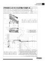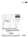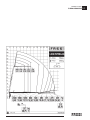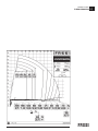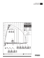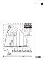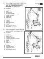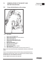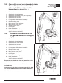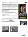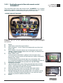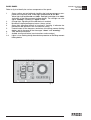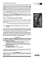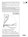
1
FASSI CRANE F290A/F310AXP.26 use and maintenance FROM SERIAL NUMBER *5001* INDEX 1 INTRODUCTION 2 2.1 2.2 2.3 CLASSIFICATION OF THE CRANE MODEL Generality Hydraulic jibs Technical data 3 3.1 3.2 CAPACITY PLATES Generality Capacity plates with lifting moment limiting device 4 HYDRAULIC SCHEMATICS (version with lifting moment limiting device) ( ) 5 ELECTRIC SCHEMATICS (version with lifting moment limiting device) ( ) 6 SAFETY NORMS 7 7.1 7.2 7.3 7.4 7.5 WARNING AND INSTRUCTIONS Generality Before operating During operation At the end of the operation (Prior to driving the vehicle) Residual risks 8 8.1 8.2 IDENTIFICATION OF THE CRANE MODEL Generality Crane mark 9 9.1 9.2 9.3 CRANE NOMENCLATURE Crane with distributor on the column Crane with ground controls on both sides Crane with ground controls on both sides and with top seat controls by hand cables Crane with top seat controls and with ground controls for outriggers 10 10.1 NOMENCLATURE OF THE SAFETY AND PROTECTION DEVICES Crane with distributor on the column 11 11.1 11.2 SUPPLEMENTARY BEAMS Generality Identification of the supplementary beams 12 TILTABLE OUTRIGGER RAMS (not available) 13 13.1 13.2 13.2.1 13.2.2 13.3 13.4 13.5 MANOEUVRES AND CONTROLS TO STABILIZE THE VEHICLE Generality Functions of control levers for stabilization with horizontal distributor Functions of control levers for stabilization with vertical distributor Functions of control levers for stabilization with radio-remote control Controls to stabilize the vehicle Manualy tiltable outrigger rams Crane with hydraulic tiltable supports (with hydraulic motor) for outrigger rams 14 CONTROLS TO OPERATE THE CRANE Edition 29.12.2009 1 14.1 14.2 14.2.1 14.2.2 14.2.3 14.2.4 14.3 14.4 14.5 14.6 14.7 14.8 14.9 15 16 16.1 16.2 16.3 16.4 16.4.1 16.4.2 16.4.3 16.4.4 16.4.5 16.5 16.6 16.7 16.8 16.8.1 16.9 16.9.1 17 17.1 17.2 17.3 18 18.1 18.2 Generality Radio-remote control Use of the radio-remote control Push-button panel of the radio remote control “RCH” Push-button panel of the radio remote control “SCANRECO” Icon legend Emergency station from the column (if accessible) Manoeuvres to unfold the crane into a working condition Manoeuvres to fold the crane into the rest condition Manoeuvres to unfold the crane “C” into a working condition (only for the crane version C) Manoeuvres to fold the crane “C” into the rest condition (only for the crane version C) Indicator of inner boom horizontal position (on request) Stand-up control station (if fitted) MANOEUVRES OF THE CRANE LOADS (version with load limiting device) (not available) MANOEUVRES OF THE CRANE LOADS (version with lifting moment limiting device) ( ) Generality Lifting moment limiting device “EVOLUTION” (LMEV) and automatic dynamic control (ADC) Control panels of the lifting moment limiting device (if fitted) Load handling “Block due to overload condition” “Winch off” (when fitted) “Lifting block” (Prolink) Other functional characteristics Visual indicator yellow/red light Lifting moment limiting device for two working sectors Rotation limiting device Setting menu Diagnostic: alarms and warnings Emergency control station on the column and exclusion tap lever XP device Activation and instructions for use of the XP/CR device USE OF IMPLEMENTS Generality Hydraulic connections for implements - supplementary hoses Oil cooler (heat exchanger) MANUAL EXTENSIONS Generality Lifting moment limiting device “ELECTRONIC” for the manual extensions (see “Setting Menù”) 19 CONTROLS TO OPERATE THE HYDRAULIC IMPLEMENTS OF THE CRANE 20 20.1 20.2 20.3 20.4 20.5 20.6 20.7 20.8 21 21.1 21.2 21.2.1 22 22.1 22.2 22.3 22.4 22.5 22.6 22.7 22.8 23 24 24.1 24.2 24.3 25 HYDRAULIC JIBS Generality Identification of the hydraulic jib Nomenclature of the hydraulic jib Manoeuvres to unfold the jib in working condition Manoeuvres to fold the jib in rest condition Operations to remove the hydraulic jib from the crane Operations to mount the hydraulic jib on the crane Crane with lifting moment limiting device and "Prolink" (if fitted) WINCH (if fitted) Generality (version with lifting moment limiting device) Winch for crane (version with lifting moment limiting device) Winches equipped with a mechanical stroke end device (version with lifting moment limiting device) MAINTENANCE INSTRUCTIONS Generality After every 8 working hours or at the end of every working day After every 40 working hours or after every working week After every 100 working hours or more frequently in case of more intensive utilisation After every 500 working hours or after every 6 working months After every 1000 working hours or after every working year Complete overhaul of the crane is required when 10.000 working hours or 10 years'life are reached Instructions for the dismantlement and the demolition of a FASSI crane TABLE OF HYDRAULIC OIL AND LUBRICANTS CHARACTERISTICS POSSIBLE FAULTS Generality Only operations which can be carried out by the user Operations to be carried out only by a service center INSTRUCTION AND WARNING PLATES 1 FASSI CRANE Use and maintenance TRANSLATION OF THE ORIGINAL INSTRUCTIONS THANK YOU FOR SELECTING ONE OF FASSI CRANES. This crane is the result of FASSI philosophy: ongoing research, rigorous testing, data verification, and analysis of performances. Many years of experience has allowed us to grant you the maximum safety of operation together with the optimization of machine performances. All this represents the core of FASSI quality system. FASSI quality system is in conformity with UNI EN ISO 9001:2008 (ISO 9001:2008) FASSI cranes conform with the European Norm EN12999 The fitment of the crane on the vehicle must be carried out in accordance with the instructions given by FASSI in the manual for hydraulic crane fitting and the relevant chassis manufacturers directives. The Manufacturer declines all responsibility and guarantee if the fitting is entrusted to workshops without sufficient technical capability to carry out the work in conformity. Be sure that the unit has been installed, inspected and tested in accordance with the local legal requirements. As well as the principal safety norms, this manual contains a description of the crane and the instructions for use and maintenance. The following instructions refer to mobile cranes in general and must be integrated with the manual for use supplied by the centre responsible for the crane fitting on truck, vehicle or other type of structure. Some of the options described in the use and maintenance manual are available only on request; therefore they may not be on your crane. READ THIS MANUAL CAREFULLY prior to use or any maintenance. A few minutes spent now could save time and labour later. Always conform to the safety norms and the instructions for use and maintenance contained in the present manual in order to guarantee a long life to the crane. NOTE The original version of the present manual is in italian. The spare parts catalogue for the crane can be viewed in the Internet site: www.fassicat.com INDEX GRU FASSI 1 INDEX GRU FASSI ICONS LEGEND (CE Declaration of conformity) IT Gru Prolunga idraulica Radiocomando Verricello Traversa stabilizzatori supplementari Prolunga manuale Carrucola GB IE CY Loader crane 3rd boom Remote control system Hoist Stabilizer Boom extension manual Sheave FR BE LU Grue de chargement 3ème flèche Système à télécommande Palan Traverse supplémentaire Rallonge de flèche manuelle Poulie DE AT LU Ladekran Winde Zusatzabstützungen LI Manuelle Armverlängerung Seilrolle CH CH Hydraulische Funkfernsteuerung Knickverlängerung Laadkraan 3e mast Afstandsbedieningssysteem Hijsinrichting Stabilisator Mastverlenging, handmatig Katrolschijf Grua industrial de carga 3º braço Sistema controlo remoto Guincho Estabilizador Braço extensível, manual Roldana ES Grúa Prolonga hidráulica Mando a distancia por radio Cabrestante Estabilizadores suplementarios Prolonga manual Polea SE Kran Jib Radiostyrning Vinsch Extra stödbensbrygga Manuell förlängningsarm Linhjul FI Kuormausnosturi Jibipuomi Radio-ohjaus Vinssi Tukijalka Mekaaninen puominjatke Taittopyörästö DK Lastekran 3. udskud Radiostyring Løft Støtteben Manuelt udskud Blok LV Hidromanipulators 3-ā izlice Distances vadības sistēma Vinča Stabilizators Izlices pagarinājums, manuāls Bloks LT Krovinių kėlimo kranas Papildoma strėlė Nuotolinio valdymo sistema Gervė Atrama Mechaniškai išilginama strėlė Skriemulys EE Hüdrotõstuk 3 poom Ditants juhimine Vints Tugijalad Mehaaniline pikendus (Vintsi) plokk CZ Nakládací jeřáb Třetí hydraulické rameno Dálkové ovládání Zdvihadlo Podpěra Výsuv ramene, manuální Kladka Nakladací žeriav 3. výložník Diaľkové ovládanie Naviják Stabilizátor Manuálne predĺženie výložníka Kladka Żuraw przeładunkowy Bocian Sterowanie radiowe Wciągarka Podpory Ramię wysuwane ręcznie Zblocze Manipulativno dvigalo Zglobna roka Sistem daljinskega upravljanja Vitel Stabilizator Teleskopski podaljšek, ročni Škripec HU Önrakodó daru Lengőgém Rádió távirányító rendszer Emelőszerkezet Kitalpaló Mechanikus gémtoldat Görgő RO Macara incarcator Extensie hidraulica brat Telecomanda Troliu Stabilizator Extensie manuala brat Scripete Кран Хидравлично удължение Дистанционно управление Лебедка Напречна греда допълнителни стабилизатори Ръчно удължение Шайба TR Yükleyici vinç Üçüncü bom Uzaktan kumanda sistemi kaldırma Dengeleyici Manüel bom uzatma Kasnak MT Loader krejn 3 boom Sistema Motorizzata Arblu Stabbilizzatur Estenzjoni tal boom, Manwali Taljola , NL PT SK PL SI BG GR 3η IS Hleðslukrani 3ja bóma Fjarstýring Spil Krana lappir handútdrag Svívill NO Lastebilkran Hydraulisk rorlenger Radio styring Vinsj Støtteben Teleskoparm manuell Skive 1 2 CLASSIFICATION OF THE CRANE MODEL 2.1 CLASSIFICATION OF THE CRANE MODEL F 290A/310AXP.26 Generality The design of this crane has been carried out in respect of fatigue test classification H1B3 of the EN12999 norm. The crane can operate, intermittently, with lifting devices other than the hook. The dimensions and the capacity of the implements must be proportioned with crane performances. 2.2 Hydraulic jibs Extension type L212 L213 L214 2.3 Hydraulic jibs Weight=kg Manual Weight=kg Manual Weight=kg 500 ML21 44 NL21 29 580 ------------------------ NL21 29 650 ------------------------ ----------------------- Manual PL21 PL21 PL21 Weight=kg 17 17 17 Technical data F 290A/310AXP.26 Lifting capacity Standard reach Hydraulic extension Rotation arc 25,79 tm 253 kNm 16,70 m 12,05 m 400° 28,03 tm 275 kNm 16,70 m 12,05 m 400° Rotation torque Working pressure Pump capacity Oil tank capacity Crane weight Max. working pressure on the outrigger (Φ 200) 4,18 tm 31,0 MPa 60/80 l/min 41,0 kNm 195 l 4130 kg 49,6 daN\cm2 F290A.26 4,18 tm 32,5 MPa 60/80 l/min 41,0 kNm 195 l 4130 kg 49,6 daN\cm2 F310AXP.26 2 CLASSIFICATION OF THE CRANE MODEL F 290A/310AXP.26 2.3 CLASSIFICATION OF THE CRANE MODEL F 290A/310AXP.26 2.3 CLASSIFICATION OF THE CRANE MODEL F 290A/310AXP.26 2.3 3 CAPACITY PLATES 3.1 Generality The represented plates refer to the nominal design capacities. (!) WARNING (!) If the capacities are downgraded or partially reduced (e.g. sector in front of vehicle cab) capacity plates must be applied in line with the final test figures. 3.2 Capacity plates with lifting moment limiting device CAPACITY PLATES F 290A/310AXP.26 3 CAPACITY PLATES F 290A/310AXP.26 3.2 CAPACITY PLATES F 290A/310AXP.26 3.2 CAPACITY PLATES F 290A/310AXP.26 3.2 CAPACITY PLATES F 290A/310AXP.26 3.2 CAPACITY PLATES F 290A/310AXP.26 3.2 CAPACITY PLATES F 290A/310AXP.26 3.2 CAPACITY PLATES F 290A/310AXP.26 3.2 CAPACITY PLATES F 290A/310AXP.26 3.2 CAPACITY PLATES F 290A/310AXP.26 3.2 CAPACITY PLATES F 290A/310AXP.26 3.2 CAPACITY PLATES F 290A/310AXP.26 3.2 CAPACITY PLATES F 290A/310AXP.26 3.2 4 HYDRAULIC SCHEMATICS (version with lifting moment limiting device) Hydraulic schematic for crane - Danfoss distributor D850 - “electronic” lifting moment limiting device - CE CODE DESCRIPTION DI860 DV020 IG402 FI782 FI880 M1/M2/M3 RU976 TR003 VA215 DISTRIBUTOR DEVIATOR INTEGRATED ASSEMBLY OF LIMITING DEVICE OIL FILTER (HIGH PRESSURE) OIL FILTER (RETURN) GAUGE QUICK CONNECTION FAUCET PRESSURE TRANSDUCER OIL FLOW CHECK VALVE VA227 VA239 VA257 VA264 VA265 VA266 SEQUENCE VALVE SIMPLE EFFECT BLOCK VALVE SEQUENCE VALVE SIMPLE EFFECT BLOCK VALVE DOUBLE EFFECT BLOCK VALVE REGENERATIVE VALVE HYDRAULIC SCHEMATICS GR4 240B_290A_330D EVOLUTION 4 Hydraulic schematic for crane - Danfoss D900 distributor - “electronic” lifting moment limiting device - CE CODE DESCRIPTION DI860 DV020 IG503 FI782 FI880 M1/M2/M3 RU976 TR003 VA215 DISTRIBUTOR DEVIATOR INTEGRATED ASSEMBLY OF LIMITING DEVICE OIL FILTER (HIGH PRESSURE) OIL FILTER (RETURN) GAUGE QUICK CONNECTION FAUCET PRESSURE TRANSDUCER OIL FLOW CHECK VALVE VA227 VA232 VA239 VA257 VA264 VA265 VA266 SEQUENCE VALVE UNIDIRECTIONAL VALVE SIMPLE EFFECT BLOCK VALVE SEQUENCE VALVE SIMPLE EFFECT BLOCK VALVE DOUBLE EFFECT BLOCK VALVE REGENERATIVE VALVE HYDRAULIC SCHEMATICS GR4 240B_290A_330D EVOLUTION 4 Hydraulic schematic for crane - Variants 1 CODE DESCRIPTION SC012/14 VA175 VA185 VA187 VA286 OIL COOLER (HEAT EXCHANGER) BLOCK VALVE WITH FAUCET SELECTOR VALVE BLOCK VALVE WITH FAUCET REGENERATIVE VALVE WITH ELECTRIC DEACTIVATION HYDRAULIC SCHEMATICS GR4 240B_290A_330D EVOLUTION 4 Hydraulic schematic for crane - Variants 2 CODE DESCRIPTION DV016 VA185 DV018 FLOW REGULATOR VALVE (diam. 4 mm) SELECTOR VALVE ELECTRIC DEVIATOR HYDRAULIC SCHEMATICS GR4 240B_290A_330D EVOLUTION 4 5 ELECTRIC SCHEMATICS Electric schematic for crane SYMBOL DESCRIPTION ALIM FX800 FARI EV1 EV2 EV3 EV4 GENERAL FEEDING ACTIVATION WORK LIGHTS ELECTROVALVE FOR CRANE BLOCK ELECTROVALVE DOUBLE LIMITING DEVICE XP ELECTROVALVE ELECTROVALVE FOR PRESSURE REDUCTION OF REGENERATIVE EXTENSION EXIT REGENERATIVE ELECTROVALVE CENTRAL PROCESSING UNITY USER PANEL PROXIMITY MICROSWITCH FOR ROTATION CONTROL WINCH LOAD LIMITING DEVICE YELLOW LIGHT 90% LUMINOUS TOWER RED LIGHT 100% RUN END WINCH OPTIONS CONTACT FOR PLATFORM RECEIVER OF THE RADIO SELECTOR REMOTE/MANUAL FOR CRANE USE WITH RADIO OR MANUAL WINCH LOAD LIMITING DEVICE CONNECTION SENSOR HYDRAULIC JIB CONNECTING DEVICE EV5 FX800 FX801/A/G IP1/2/3 LCV LG LP LR MV2 OPTION PLE RC MAN FX002/1/2 S3 TEMP1+SC TI1 TI2 TP0 TP1 TP2 TP3 SENSOR ACTIVATION WARMTH EXCHANGING DEVICE SENSOR OF CORNER ON SECUNDARY ARM SENSOR OF CORNER ON HYDRAULIC JIBS PRESSURE TRANSDUCER FOR DISTRIBUTOR PRESSURE TRANSDUCER FOR INNER RAM PRESSURE TRANSDUCER FOR SECONDARY RAM PRESSURE TRANSDUCER FOR THE JIB RAM IP4 SENSOR OF PROXIMITY CONTROL STATION PROTECTION FTC PHOTOCELL OPERATOR PRESENCE ON CONTROL STATION DF FLOW DEVIATOR (FOR VERSIONS FROM GROUND AND FROM SEAT) FX804 CONTROL UNITY EXTENSIONS/STABILIZERS ALIM FX804 FEEDING FX804 EVE1…EVE4 ELECTROVALVE FOR CONTROL EXTENSION 1… EXTENSION 4 EVS1…EVS4 ELECTROVALVE FOR CONTROL STABILIZER 1… STABILIZER 4 EVR / EVU ELECTROVALVE FOR CONTROL EXIT/RETURN EXTENSIONS/STABILIZERS EVDEV ELECTROVALVE FOR CONTROL ELECTRICIAL DEVIATING DEVICE CRANE/STABILIZERS ELECTRIC SCHEMATICS EVOLUTION 5 6 SAFETY NORMS SAFETY NORMS GR2_3_4_5 Strictly conform to the norms reported by the plates DE2499B (fig. 1) or DE1771B (fig. 1a) placed next to the controls, in order to avoid possible accidents while operating the crane. Only authorized persons are allowed to operate the crane. The crane must be used on firm, level ground. Check that the vehicle hand brake is on and that the wheels are chocked. Before every operation make sure that: - no-one is within the working area of the crane; - the safety devices are in place and operative; - the minimum safe working distances from power lines are observed; - the load is correctly slung and hooked. Stabilize the vehicle by the outrigger rams, making sure that: - the lateral supports are fully extended; - the wheels are in contact with the ground and the suspension is not completely unloaded. VERTICAL VERSION fig. 1 Use the crane in accordance with the use and maintenance manual, making sure that: - the load and radius are within the maximum limits shown on the crane capacity plate; - the crane is used progressively avoiding sudden load movements - swinging or dragging of the load is avoided; - the load is lifted before rotating. When using implements protect the crane working area with a barrier. The vehicle/crane are not left unless the power take off is disengaged and the load is on the ground. Before driving the vehicle make sure that the outriggers are fully retracted and re-entered, the safety taps closed and the crane is in folded position. HORIZONTAL VERSION fig. 1a 6 INSTRUCTION PLATE AND SAFETY NORMS LEGEND (DE1771B - DE2499B) It is obligatory to use the necessary individual protection devices. Make sure that the load and radius are within the maximum limits shown on the crane capacity plate. The stability of the unit (crane-vehicle) is only guaranteed by the complete lateral extension of the outriggers. It is prohibited to walk or stop under a suspended load. Be very careful when stabilizing the vehicle; make sure that no one is or transits in close proximity of the working area of the outriggers. During positioning of the crane into a working / rest condition, you must operate from the opposite side of the crane opening / closing; it is forbidden to operate from the side of the crane opening / closing because of the overall dimensions of the booms. Respect the safety distances from electric lines. The minimum distance is five (5) meters, except for otherwise prescribed by national norms. Avoid the direct water jets. Read the USE and MAINTENANCE manual carefully prior to start (up) or use the crane or any maintenance. (!) ATTENTION (!) It exist a series of residual risks, not predictable completely, which can create danger for the employed in the crane handling. (See Chapter 7.5 "Residual risks") SAFETY NORMS GR2_3_4_5 6 7 WARNING AND INSTRUCTIONS 7.1 Generality The use of the crane is reserved to authorized personnel, instructed in advance, who has to conform to the safety norms and instructions contained in the Use and maintenance manual supplied with the crane. (See norms ISO 9926-1). It is prohibited to walk or stop under a suspended load. It is prohibited for unauthorized persons to be within the working area. Under no circumstances interfere with the safety and protection devices. Warning plates, as well as instruction and operation plates, must be replaced when no longer readable or missing. See Paragraph "25 Instruction and warning plates". Do not use the outriggers to raise the vehicle. To avoid hitting bridges or tunnels check and record the overall height of your crane in the folded position or in laid position in the body or on the load. Always respect and pay proper attention to road signs placed in proximity of such obstacles. Do not run the engine in a indoor area without first making sure there is adequate ventilation. Take the vehicle fumes away from the working area by fitting an extension tube of a suitable diameter and a right length to the exhaust system. When using the ladder to reach the control station on the top seat, avoid knocking into the controls while going up or down the ladder. The control station on the top seat is provided with side safety guards; stay within these guards. The crane must be activated only in the stability conditions. Park the vehicle correctly and insert the parking brake. 7.2 Before operating (!) ATTENTION (!) Make sure that the protections are in their place and that all the safety devices are fitted and active (See norms ISO 9927-1). Keep the ladder and the control station on the top seat clean (if present). Normally, the seat can be tilt forward. Make sure that control stations, the instruction plates and the loading charts are properly lit and visible, so as to ensure safety while operating. Pay attention to not crash against the control station on the top seat (if fitted) during manoeuvres. Check that the working area is adequate and properly lighted for your crane. Make sure that the hook is always free to rotate on its pin and that nothing obstructs its vertical positioning. Check the efficiency of the hook safety catch. Carefully inspect the condition of ropes or chains (if present). Make sure that the pallet fork (if present) is connected to the crane hook by means of a chain having at least three (3) rings. WARNING AND INSTRUCTIONS GRU FASSI 7 7.3 During operation WARNING AND INSTRUCTIONS GRU FASSI Locate and delimit the working area. Make sure that no one is within the working area of the crane. Do not stop and do not pass in the delimited area. Choose the correct control position, making sure to have the complete visibility of the working area. Stabilize the vehicle on a horizontal plane with a maximum tolerance of 1,5 degrees. Check the vehicle inclination on the levelness indicator. The bubble must be contained in the internal circle, and in any case it doesn't must to come out from the external circle. Make sure that the outrigger rams rest on a solid base. If necessary use larger outrigger base plates (available on request) to avoid sinking. If you adopt other means, make sure that they are suitably sized for the load they must bear. (!) ATTENTION (!) The stability of the unit (crane-vehicle) is only guaranteed by the complete lateral extension of the outriggers and by the observance of the capacity plates. The value of the pressure exercised on the ground by the stabilizers is indicated in the table at paragraph "2.3 Technical Data" and it has to be compared with the below table. ADMITTED PRESSURE ON THE GROUND (Load capacity of the ground) - Rif. DIN 1054 A B C Made ground, not compacted artificially Asphalt Compact ground, not removed 1. Mud, peat, marshy ground 2. Not compacted ground, adequately solid From fine to middle sand From thick sand to gravel Shattered and compacted stones 3. Compact ground Wet Soft Compact Half - solid Hard (solid) 4. Rock Eroded 0 - 10 daN/cm² 20 daN/cm² 0 daN/cm² 15 daN/cm² 20 daN/cm² 25 daN/cm² 0 daN/cm² 4 daN/cm² 10 daN/cm² 20 daN/cm² 30 daN/cm² 100 daN/cm² 7.3 (!) ATTENTION (!) Carefully inspect the load rigging. WARNING AND INSTRUCTIONS GRU FASSI Hook up the load, checking that it does not exceed the capacity indicated on the lifting diagram specific to each load configuration. Make sure that the lifted load is balanced. (!) ATTENTION (!) Avoid swinging the load above working and transit areas. Any hidden danger situation must be audibly alarmed. Avoid swinging the load above the control station. In cases where the load is too close, the crane must be operated from the opposite side or with the radio-remote control (if fitted). During the loading and unloading operations it is prohibited to leave the control station or the control at a distance. Activate the controls with slow and progressive movements. Move the load with the greatest caution, and avoid swingings and collisions. Avoid the rapid displacements and the temporary stops, since they can cause the load swinging. Do not rotate the crane before the load is lifted. Rotate slowly and with care paying attention to the stability of the vehicle. With vertical lift, on hydraulic and mechanical extension, rotate slowly in order to avoid side-skidding. (!) ATTENTION (!) Handle the wet or frozen load with the maximum attention: it exists the skidding danger. It's obligatory to clean the load from the ice or the snow before lifting. When operating through a winch, lift the load vertically using the cable and not the booms in order to avoid swinging the load. This machine is suitable for lifting things. Don’t use it for lifting people. Exception: it is possible to use the basket for lifting people only after evaluation of conformity by a notified body (EN 280). The possible combinations with basket are available by all FASSI dealers and are listed in the detailed technical documentation available in every FASSI authorised assistance centre. It is prohibited to unblock, hit, pull or drag the loads. It is prohibited the lateral traction or the vehicles drawing. It is prohibited the use for wood or scrap iron. It is prohibited to fix loads where not foreseen. It is prohibited the excavation with grabs. (!) ATTENTION (!) Do not utilize the crane for pushpull (F), lateral (F) or sideways (F) operations. Crushing (F) or push (F) manoeuvres are not permitted. Never operate the outriggers when the crane is loaded. (!) ATTENTION (!) The vehicle\crane must not be left unless the load is on the ground, the booms of the crane (and of the hydraulic jib), are folded and laid on a solid base and the power take-off is disengaged. Do not move the vehicle when the crane is not in transport position. Do not move the vehicle with a load suspended on the crane. (!) ATTENTION (!) Avoid working conditions which present danger for the operator and the persons present in the action area of the crane, the outriggers or the load. 7.3 - CRUSHING DANGER / SHEARING DANGER Avoid all those situations which may result in crushing during vehicle stabilization, crane movement and load handling. The table indicates the minimum safety working distances concerning the various parts of the body. The figures illustrate circumstances which may turn out to be dangerous if you fail to respect the minimum safe distances and if it is impossible to introduce larger parts of the body. (In conformity with EN 349 standard the minimum safe working distances to avoid crushing parts of the body) Parts of the Body Minimum safe working distance mm Body 500 Leg 180 Toes Hand Wrist Fist Figure Parts of the Body Minimum safe working distance mm Head 300 Foot 120 50 Arm 120 100 Finger 25 Figure (!) ATTENTION (!) Failure to respect the minimum safe distances may result in a safety hazard and a deadly risk. (!) ATTENTION (!) For designated areas as: outrigger running towards rest position, leaning and folding points of the booms in rest position, control platform and swinnig column, top seat and running inner boom, where no carter is possible to be placed, please observe the shear and trapping hazard stickers nearly placed. - ELECTROCUTION DANGER General safety precautions for the operator and potential co-workers. (!) ATTENTION (!) Respect the safety distances from electric lines; the minimum distance is, according to CEN norms, five (5) meters, except for otherwise prescribed by national norms. Failure to respect the minimum safe distances may result in electrical hazards for the operator and his assistants. If the crane comes into contact with an electric line, it's necessary to follow the next procedure: - If the crane hits an overhead power line, do not touch the crane, the truck or the load. - Carefully evaluate the danger before moving. If you are closer than 10 meters from the crane, the truck, the load or the electric line, move at least 10 meters away, by shuffling away with small steps, in order to minimize the chance of getting a too high voltage difference between the feet. - Warn others to stay away. - Call for help and contact the power company to de-energize the line. Do not attempt to assist someone in direct or indirect contact with the power line before the power has been disabled: you run the risk of being electricuted yourself. WARNING AND INSTRUCTIONS GRU FASSI 7.3 - If you are in the truck cabin, stay inside without touching the bodywork: it is more dangerous if you go out before the line is de-energized. - Help the electricuted person if you know the first-aid procedures, otherwise wait for the paramedics to arrive. (!) ATTENTION (!) A wind gust can cause the swinging of an electric line. Do not utilize the crane during thunderstorms and when wind speed exceeding 13,8 m\s (50 km/h), maximum value of the Beaufort scale degree 6. Force of the wind Beaufort scale Wind speed m/s Classification Characteristics 0 0,0 - 0,2 Calm Calm wind, smoke goes up quite vertically 1 2 0,3 - 1,5 1,6 - 3,3 Light breeze Smoke reveals the direction of the wind, one can feel the wind blowing, leaves start fluttering. 3 4 3,4 - 5,4 5,5 - 7,9 Moderate breeze Leaves and branches are in constant motion, small branches start fluttering. Dust and papers dance on the ground. 5 8,0 - 10,7 Fresh breeze Small green branches bend, the surface of waterways and lakes are wavy. 6 10,8 - 13,8 Near gale Big branches bend, wind whistles through high-tension cables, it's difficult to walk keeping the umbrella open. 7 13,9 - 17,1 Moderate gale Trees sway, it's hard to walk 8 17,2 - 20,7 Storm wind Branches get broken, it's hard to walk. 9 20,8 - 24,4 Storm It damages houses (antennas and roof tiles fall down) (!) ATTENTION (!) The non-conformity with the use instructions provided in the current manual implies dangers for the safety of people and things and also the loss of every form of responsibility and warranty. - BURN DANGER During the oil flow in the hydraulic circuit, the oil and all the components of the circuit reach high temperatures. It's necessary to verify the temperature of every hydraulic component before to touch it, for to avoid burns. - NOISE EMISSION (!) ATTENTION (!) Permanent low or short high noise emission levels can damage the health of operators and other people in the working area. The risk due to noise is mainly caused by truck engine and/or auxiliary hydraulic supply system. The installer must provide for the phonometric assessment after assemblage, according to the reference standard. (!) ATTENTION (!) In case of danger due to noise pollution, use the necessary protection devices. WARNING AND INSTRUCTIONS GRU FASSI 7.3 In places of command of loading cranes which are mounted on Diesel motor vehicles, the noise emission level depends on vehicle model and working conditions, so the following values can be reached: - 72 to 84 dbA with low or high idling speed of the truck motor - 79 to 86 dbA in crane work - the maximum noise level is between 92 and 100 dbA. (!) ATTENTION (!) It is recommended to maintain a low idling speed to reduce noise pollution. If you use the radio-remote control, it is recommended to maintain a distance from the vehicle motor greater than 1 m. - USE TEMPERATURE AND CRANE STORING The crane is designed for the utilization at ambient temperature included in the below table. If the ambient temperature of utilization is not included in the indicated limits, the crane functionality can be compromised. Temperatures too high or too low can damage the components of the oleodynamic and electric circuit, and compromise the crane functioning. If the crane is used in the presence of ice or snow, it's necessary to start the hydraulic system at the minimum speed of the motor. It's necessary to do circulate the oil for some minutes, until to its heating. (!) ATTENTION (!) It's obligatory to clean the load from the ice or the snow before lifting. USE TEMPERATURE AND CRANE STORING Temperature of the working ambient of the crane Temperature of the storage ambient of the crane -30°C to +50°C -40°C to +70°C (!) ATTENTION (!) If you work at ambient temperature different from that prescribed in the table, it's obligatory to request the specific authorization to the FASSI GRU. WARNING AND INSTRUCTIONS GRU FASSI 7.3 7.4 At the end of the operation (Prior to driving the vehicle) WARNING AND INSTRUCTIONS GRU FASSI Unhook the load, and make re-enter the crane booms. Fold the crane. Make the re-enter of the outrigger cylinders one at a time, checking every single organ in motion. The operator must have a full visibility during every operation of re-entry of the stabilization organs. Make sure that the outrigger supports and rams are re-entered within the overall width of the truck and locked by the safety devices. If the booms of the crane (or of the hydraulic jib) are to be laid on the body or on the load, they must be suitably blocked to prevent possible sideways movements. Make sure that the indications about the overall dimensions are respected. Implements can be left mounted on the booms of the crane (or of the hydraulic jib) only if the overall dimensions are respected. They must be suitably blocked to prevent possible sideways movements. If an accessory (fork, ...) is mounted, it must be tied down at all times during transport. Disengage the power take off. Fix the load adequately, to avoid the fall of the load from the vehicle during march. (!) ATTENTION (!) After having closed the crane, and having do the re-enter of the outriggers, it's necessary to fix all the crane organs, to avoid the booms or outriggers exit during the vehicle march. Hook all the fixing devices correctly. (!) ATTENTION (!) Annotate the maximum dimensions of the vehicle, included the possible transported load. Respect the greatest height of volume for the transit below the tunnels, bridges, subways, tension lines and the maximum axial loads consented from the vehicle. 7.4 7.5 Residual risks Utilize the crane only for the provided aims by the Use and Maintenance manual. It is prohibited the crane utilization for differents aims to those indicated in the Use and Maintenance manual. (!) ATTENTION (!) It is prohibited the crane utilization not by qualified staff. The operator is responsible for the machinery, its movements, the load movement and all the working area of the crane. Therefore it's necessary the maximun attention in all the phases of the crane opening and closing, of stabilization and of the load handling, it exist a series of residual risks, not predictable completely, which can create danger for the employed in the crane handling In the below list are indicated some residual risks, that have as danger a relieved and in movement load, which request particular attention during the working period. MOMENT LIMITING DEVICE Never try to bypass nor tamper with the moment limiting device and the various safety systems installed on the crane. In such case the operator shall be held responsible for the subsequent crane performance. It is also important to understand the alarm messages generated by the "moment limiting device" and act consequently. CONTROL SEAT Before operating from the control seat, the operator shall make sure that he is safe from hazards (i.e. stand clear of the load, make sure that there is a way of escape,..). Otherwise he shall manoeuvre from a different control seat: if there is none available, the crane should be equipped with a radio control or remote control in order to allow the operator to operate the crane in absolute safety. From the control seat the operator shall be able to visually inspect the whole working area at all times. If it is not possible, must team up with a co-worker able to control the whole area: otherwise the crane shall be equipped with a radio control in order to ensure the operator with the perfect position to see all potential hazards clearly at all times. The operator shall also teach this eventually co-worker with the scope of not harm each other with control commands. LOAD RIGGING Carefully inspect the load rigging. The operator shall make sure that the load is properly attached and balanced and that all unexpected movements are not allowed. Be careful not to hit any potential impediments during the crane movements. If the load sticks out of the maximum volumes of the vehicle, the operator must make sure of the new maximum dimensions of volume, to avoid collisions with the tunnels, the subways, the bridges and the electric lines. JOBSITE CONDITIONS Enclose the working zone. Prior to use, make sure that the working area is free and clear of potential obstacles to crane operations (people, building walls, balconies, eaves, scaffoldings, tree branches, other lifting means or machines, electric lines,…). This may hurt people, damage both the impediments and the crane, and provoke also the crane overturn. Make sure that there is no risk of elements falling on the operator or on the crane and take the right precautions to prevent it. WARNING AND INSTRUCTIONS GRU FASSI 7.5 OVERLOAD AND/OR FATIGUE The crane can break down due to fatigue or overload: - If it is misused (with cycles, loads or pump oil flow not pertinent to the crane class) - If it is used for improper tasks (side, oblique or reversal pull) - If it is used in poor jobsites (corrosive environment, too high or too low temperature, foundry,… [see conditions of use]) - If the load exceeds the rated capacity indicated on the relevant plates Utilize the crane only for the provided aims by the Use and Maintenance manual. It is prohibited the crane utilization for differents aims to those indicated in the Use and Maintenance manual. WRONG MANOEUVRING The directives in force impose a suitable training of the personnel before using these types of machines, and require an adequate psychophysical condition to operate safely a lifting device that always implies the intrinsic danger of a lifted load. The crane can fall break or overturn if the operator performs a wrong manoeuvre, due to the lack of familiarity with the operation procedures or due to inadequate psychophysical conditions. WEATHER CONDITIONS Too high or too low temperatures may damage the components of the oleodynamic and electric circuits. It is forbidden to operate the crane during a storm with lightning hazards, so we recommend to fold it and put it to rest. Furthermore when the wind is too strong the crane can overturn or break down. In the chapter "7.3 During operation" are indicated the utilization limits for the temperature, the wind loads and the annexed danger (electrocution, collisions, etc.). OVERTURN The crane can overturn, thus hurting people and damaging things specially in following conditions: - if it is not correctly stabilized - if the moment limiting device is disabled - if the ground conditions at the jobsite are not stable enough with respect to the dimensions of the outrigger base and/or of the additional base plate - if you increase the design dynamic increasing the pump oil flow. In the chapter "7.3 During operation" are indicated the utilization limits for the ground consistency and the load capacity of the ground. SHEARING, ENTRAPMENT The crane has a lot of parts in movement that it is impossible to cover. The operator shall always be aware of this residual risk and keep clear from the parts in movement, particularly from the load. The operator is held responsible for himself and also for those working people in proximity of the crane, and for those who may draw closer even if not authorized. WARNING AND INSTRUCTIONS GRU FASSI 7.5 ELECTRICUTION The crane is not insulated from electric contacts and therefore it is not equipped to work under tension, even if the contact is accidental. Therefore be compliant with the min clearance prescribed by the national directives in force. Generally speaking the clearance from electric lines with a max tension of 38.000 volts should be at least 5 meters, higher tensions require higher clearance to be verified case by case together with competent technicians. The operator must consider the ambiental conditions: a wind gust can cause the crane swinging, and so a contact with the electric lines. The minimum distance of safety can differ according to typ of the electric line. It's obligatory to respect the regulation in force in the country of use for to can operate in safety. MANUAL EXTENSION OVERLOAD Manual extensions are controlled by the moment limiting device only under the conditions described in the relative chapter. The control system of the manual extension overload must be activated by the operator as described. It's prohibited to overload the extensions over the indicated limits in the capacity plates. In the chapter "3 Capacity plates" are indicated the maximum capacity of the manual extensions. ACCESSORIES Be careful when assembling and disassembling the accessories (extensions, buckets, baskets,…): verify the weight, the securing systems and the instructions for assembly and dismantlement, then appraise their barycentre and provide for adequate provisional blocking systems in order to avoid sudden movements. BREAKDOWN OF SOME SENSORS The system "moment limiting device - intelligent type" is always monitored during ignition: the system, after having activated the various circuits, checks the presence of all the inputs for around 4 seconds, and then continuously monitors the operation and the efficiency of the limiting device (approx. every 25 milliseconds). For most of the components the system checks also the congruence of the incoming signal with the one the system expects. It's obligatory to replace the damaged or spoilt components for to work with safety, and for to obtain the best performances of the crane. MAINTENANCE Maintenance is particularly important: the lack of it may damage things or hurt people. In the chapter "22 Maintenance instructions" are described all the operations for to maintain efficient your crane, and to avoid serious damages to things and persons caused by the crane malfunction for the scarce or null maintenance. (!) ATTENTION (!) The FASSI GRU declines every responsability for the spoilts, the breakings or the damages caused by the maintenance failing. PARTICULAR OPERATIONS If you are required to operate under particular conditions not illustrated in the manual of use and maintenance, analyse carefully the situation and always refer to an authorised Fassi shop or to the Fassi technical support service or to experienced operators before starting working. WARNING AND INSTRUCTIONS GRU FASSI 7.5 8 8.1 IDENTIFICATION OF THE CRANE MODEL IDENTIFICATION OF THE CRANE MODEL GRU FASSI Generality 8 The exact crane model, serial number and description of implements will enable FASSI Service Department to give a rapid and efficient response. 8.2 Crane mark The CE indicates that the crane complies with the Machines Directive (D.M.) 2006/42 (for cranes registered from 2010) or 98/37 (for cranes registered until 2009 included); it can be considered effective only with a written declaration of conformity enclosed. The cranes with the CE mark and the capacity superior to 1000 kg and/or the lifting moment superior to 40KMm is supplied with a lifting moment limiting device, that preserves the structure from possible overloads. 1 2 3 fig. 2 Identification data are marked on the plate DE5891A used for the CE mark (fig. 2) and rivetted on the base with personalized rivets FASSI. 1 - Crane model 2 - Serial Number 3 - Year of manufacturing The crane must not be put into service within the European Community unless the machine on which it is mounted also conforms with the prescribed Directive. Ever change of use, modification or addition of accessories, not specified by this manual must be affixed with a new CE mark in accordance with the Machinery Directive. A further metallic plate (fig. 3) fixed to the crane by the installer, quotes the identifying data of the equipment and the final CE mark. 1 1234- Name of the installer who applied the final CE mark Crane mark, model and serial number Vehicle mark, model and chassis number Year of mounting 2 3 4 CRANE - MARK AND MODEL SERIAL NUMBER TRUCK - MARK AND MODEL TRUCK FRAME SERIAL NUMBER YEAR OF MOUNTING (!) ATTENTION (!) It is forbidden to alter the data marked on the plates. fig. 3 9 CRANE NOMENCLATURE 9.1 Crane with distributor on the column Pos. Description 1. 2. 3. 4. 5. 6. 7. 8. 9. 10. 11. 12. 13. 14. 15. 16. 17. 18. 19. Outrigger rams Outrigger supports Base Rotation cylinders Deviator crane-outriggers Dual control for deviator crane-outriggers Outrigger distributor Outrigger double control Distributor bank Column Inner ram Inner boom Outer ram Outer boom Booms extension rams Extension boom sections Lifting hook Oil tank Manual extensions (optional) CRANE NOMENCLATURE GR4 9 9.2 Pos. 1. 2. 3. 4. 5. 6. 7. 8. 9. 10. 11. 12. 13. 14. 15. 16. 17. 18. 19. 20. 21. 22. Crane with ground controls on both sides. Crane with ground controls on both sides and with top seat controls by hand cables (on request)(fig. 1) CRANE NOMENCLATURE GR4 9.2 Description Outrigger rams Outrigger supports Base Rotation cylinders Deviator crane-outriggers Dual control for deviator crane-outriggers Outrigger distributor Outrigger double control Distributor bank Double control Column Inner ram Inner boom Outer ram Outer boom Booms extension rams Extension boom sections Lifting hook Oil tank Manual extensions (optional) Seat (optional) Hand-cables for crane (optional) fig. 1 9.3 Pos. 1. 2. 3. 4. 5. 6. 7. 8. 9. 10. 11. 12. 13. 14. 15. 16. 17. 18. 19. 20. Crane with top seat controls and with ground controls for outriggers (fig. 2) Description Outrigger rams Outrigger supports Base Rotation cylinders Deviator crane-outriggers Dual control for deviator crane-outriggers Outrigger distributor Outrigger double control Column Seat Distributor bank Inner ram Inner boom Outer ram Outer boom Booms extension rams Extension boom sections Lifting hook Oil tank Manual extensions (optional) fig. 2 10 NOMENCLATURE OF THE SAFETY AND PROTECTION DEVICES 10.1 Crane with distributor on the column Pos. Description 1. 2. 3. 4. 5. 6. 7. 8. 9. 10. 11. 12. 13. 14. Check valves for outrigger rams Check valves for rotation control (flow regulators) Check valve for inner ram Check valve for outer ram Check valve for booms extension rams Lifting moment limiting device assembly Control panels Rotation limiting device Main pressure valve (outriggers) Main pressure valve (crane) Auxiliary valves (crane) Safety device for outriggers supports Hook safety device Safety device for extension booms (only for the crane version “C”) Before crane use check that safety and protection devices are fitted and active. Under no circumstances interfere with the safety and protection devices. Interference with the check valves and removal of the lead seal remove the Manufacturer and invalidate the warranty. Use the ladder for the access to the top seat. NOMENCLATURE OF THE SAFETY AND PROTECTION DEVICES GR4 10 10.2 Pos. 1. 2. 3. 4. 5. 6. 7. 8. 9. 10. 11. 12. 13. 14. 15. 10.3 Pos. 1. 2. 3. 4. 5. 6. 7. 8. 9. 10. 11. 12. 13. 14. 15. Crane with ground controls on both sides. Crane with ground controls on both sides and with top seat controls by hand cables (on request)(fig. 1) NOMENCLATURE OF THE SAFETY AND PROTECTION DEVICES 10.2 GR4 Description Check valves for outrigger rams Check valves for rotation control (flow regulators) Check valve for inner ram Check valve for outer ram Check valve for booms extension rams Lifting moment limiting device assembly Control panels Rotation limiting device Main pressure valve (outriggers) Main pressure valve (crane) Auxiliary valves (crane) Levers guard Safety device for outriggers supports Hook safety device Safety device for extension booms (only for the crane version “C”) Crane with top seat controls and with ground controls for outriggers (fig. 2) Description Check valves for outrigger rams Check valve for rotation control Check valve for inner ram Check valve for outer ram Check valve for booms extension rams Lifting moment limiting device assembly Control panel Rotation limiting device Main pressure valve (outriggers) Main pressure valve (crane) Auxiliary valves (crane) Levers guard Safety device for outriggers supports Hook safety device Safety device for extension booms (only for the crane version “C”) fig. 1 Before crane use check that safety and protection devices are fitted and active. Under no circumstances interfere with the safety and protection devices. Interference with the check valves and removal of the lead seal remove the Manufacturer and invalidate the warranty. Use the ladder for the access to the top seat. fig. 2 11 SUPPLEMENTARY BEAMS SUPPLEMENTARY BEAMS GR4 11.1 Generality Supplementary beams are used in conjunction with the crane outriggers to ensure the vehicle stability during load handling. outrigger ram stroke mm 455(C)/560(L) 210801F 210803ME/CE 455(C)/560(L) 210802ME/CE 455(C)/560(L) 340(C)/550(L) 290800HE 541800HE 330(C)/510(L) Code 11.2 outrigger interaxis mm 2137 3103 3563 4142 4984 extension type Fixed -“H” variable manually-“H” variable manually-“H” variable Hydraulic-“H” variable Hydraulic-“H” variable Weight kg 116/123 153/160 162/169 320/340 550/575 Identification of the supplementary beams Identification data of the supplementary beam is stamped on the plate DE6839A (fig. 1). fig. 1 DE6839A 11 13 13.1 MANOEUVRES AND CONTROLS TO STABILIZE THE VEHICLE SUPPLEMENTARY BEAMS GRU FASSI Generality The outriggers rams prevent damaging stresses both to the frame and to the vehicle suspensions on which the crane is mounted to and assure the stability of the unit during load handling. (!) ATTENTION (!) Be very careful when stabilizing the vehicle; make sure that no one is or transits in close proximity of the working area of the outriggers. (!) ATTENTION (!) The crane stability is maintained by the maximum extension of the outrigger supports, by the solidity of the base underneath the plates of the outrigger rams and by the observance of the capacity plates. To check the maximum working pressure see Paragraph 2.3 Technical data DE 6409A Check that the outrigger rams are applied on a solid base; if necessary use larger outrigger base plates (available on request) to avoid sinking. When stabilization is complete the wheels of the vehicle must still be in contact with the ground and the suspensions must not be fully unloaded. Stabilize the crane so as to operate on a horizontal plane with a maximum tolerance of 1,5 degrees. While loading, it may be necessary to vertically adjust the outrigger rams to prevent an overload on the outriggers, then stabilize again. While unloading, the outrigger rams may not be perfectly in contact with the ground because of a rise in the suspension; it is therefore recommended to stabilize the vehicle during operation to avoid an overturn. DE 4491 13 13.2 Functions of control levers for stabilization with horizontal distributor SUPPLEMENTARY BEAMS GR4 - EVOLUTION 13.2 The controls to stabilize the vehicle are activated only from ground level and on both sides of the crane base. GRAPHIC SYMBOLS (See Paragraph 25 Instruction and warning plates) The graphic symbols illustrated hereunder are marked on the plates (DE6251-DE6252DE4496-DE4489) affixed next to the control stations and indicate with the following symbolism. They indicate the position of the operator in relation to the vehicle and the crane. Lever CD for selecting outrigger ram or outrigger support Levers D Deviator -E/S Lever C to control outrigger support or outrigger ram fig. 1b fig. 1a Lever function D - CD - C Levers D Control for deviator crane-outriggers ( (fig. 1a) - E\S ). CD C Levers CD Control for selecting the supports or the outrigger rams. (fig. 1b) Levers C Control for the support or the outrigger ram selected (fig. 1b) D C D Gripping the levers, the "multifunction" control group adopted allows to select and manoeuvre the outrigger support or the ram. The function happens through simultaneous operation of the selecting lever CD and the control lever C. Exemple To select the support E2 or the outrigger ram S2 - Position the lever CD (corresponding to outrigger support E2 and to outrigger ram S2) on E2 or S2 and keep it in position. To carry out the operation - Operate lever C to activate the exit/re-entry of outrigger support E2 or the descent/lift of outrigger ram S2 CD 13.2.1 Functions of control levers for stabilization with vertical distributor SUPPLEMENTARY BEAMS GR4 - EVOLUTION The controls to stabilize the vehicle are activated only from ground level and on both sides of the crane base. GRAPHIC SYMBOLS (See Paragraph 25 Instruction and warning plates) The graphic symbols illustrated hereunder are marked on the plates (DE4486DE4487-DE4488) affixed next to the control stations and indicate with the following symbolism. They indicate the position of the operator in relation to the vehicle and the crane. Lever CD for selecting outrigger ram or outrigger support Levers D Deviator -E/S Lever C to control outrigger support or outrigger ram Lever function D - CD - C fig. 2a -2b CD Levers D Control for deviator crane-outriggers ( - E\S ). (fig. 2a) Levers CD Control for selecting the supports or the outrigger rams. (fig. 2b) Levers C C Control for the support or the outrigger ram selected (fig. 2b) CD The "multifunction" control group adopted allows to select and manoeuvre the outrigger support or the ram, through simultaneous operation of the selecting lever CD and the control lever C. Exemple To select the support E2 or the outrigger ram S2 - Position the lever CD (corresponding to outrigger support E2 and to outrigger ram S2) on E2 or S2 and keep it in position. To carry out the operation - Operate lever C to activate the exit/re-entry of outrigger support E2 or the descent/lift of outrigger ram S2 C 13.2.1 13.2.2 Functions of control levers for stabilization with radio-remote control SUPPLEMENTARY BEAMS GR4 - EVOLUTION 13.2.2 The controls to stabilize the vehicle with radio-remote control are activated only from the push-button panel of the transmitting-console. (!) ATTENTION (!) Before starting manoeuvring of the stabilisers with the radio remote control, the operator shall make sure that their movements are fully visible. - RCH PUSH-BUTTON PANEL You can select whether to control the outrigger functions using the buttons placed on the remote control as follows: Position the rotating selector on the icon . "?outriggers?" appears on the display. Confirm the operation pressing contemporarily the left buttons "CLACSON" and "INDEX". "outriggers" appears on the display. You can select whether to control the crane functions using the buttons placed on the remote control as follows: Position the rotating selector on the icon . "?crane?" appears on the display. Confirm the operation pressing contemporarily the left buttons "CLACSON" and "INDEX". The indications of the crane load appear on the display. LINEAR PUSH-BUTTON PANEL (fig.3) The first 5 control levers on the push-button panel (beginning on the right) have two plates because they can control 5 functions of the crane or the functions for stabilization. Hereunder are reported the plates indicating the stabilization functions for every lever. LEVERS CD LINEAR PUSH-BUTTON PANEL DISPLAY fig. 3 ROTATING SELECTOR CLACSON LEVER C INDEX C CD PUSH-BUTTON PANEL WITH JOYSTICK (fig.3a) The three control joy-sticks on the push-button panel have two plates because they can control the functions of the crane or the functions for stabilization. Hereunder are reported the plates indicating the stabilization functions for the joystick. PUSH-BUTTON PANEL WITH JOY-STICK fig. 3a DISPLAY ROTATING SELECTOR CLACSON CD C LEVERS CD LEVER C INDEX Rotating selector Leve CD Leva C Selector of the icons on the display. Controls for the selection of the outrigger supports and of the outrigger rams. Control of the selected outrigger support or ram. SUPPLEMENTARY BEAMS GR4 - EVOLUTION 13.2.2 LINEAR PUSH-BUTTON PANEL fig. 4 - SCANRECO PUSH-BUTTON PANEL You can select whether to control the outrigger functions using the buttons placed on the remote control as follows: Position the rotating selector on the icon . "?outriggers?" appears on the display. Confirm the operation pressing contemporarily the buttons "INDEX" and "IGNITION". "?outriggers?" appears on the display. You can select whether to control the crane functions using the buttons placed on the remote control as follows: Position the rotating selector on the icon . "?crane?" appears on the display. Confirm the operation pressing contemporarily the buttons "INDEX" and "IGNITION". The indications of the crane load appear on the display. LINEAR PUSH-BUTTON PANEL (fig.4) The first 5 control levers on the push-button panel (beginning on the right) have two plates because they can control 5 functions of the crane or the functions for stabilization. Hereunder are reported the plates indicating the stabilization functions for every lever. LEVERS CD CD DISPLAY LEVER C INDEX ROTATING SELECTOR IGNITION Rotating selector Leve CD Leva C C Selector of the icons on the display. Controls for the selection of the outrigger supports and of the outrigger rams. Control of the selected outrigger support or ram. SUPPLEMENTARY BEAMS GR4 - EVOLUTION MANOEUVRES OF THE OUTRIGGER RAMS IN CASE OF AN ELECTRICAL FAILURE In case of an electrical failure, electrical malfunctions, you cannot use the selectors on the push-button panel and so it is necessary to operate directly the outrigger distributor bank (fig. 5). In such an emergency condition, the operator shall make sure that no one is within or passing in close proximity to the working area of the outriggers, neither from the operator side nor from the opposite side. The operator shall be able to visually see the whole working area at all times. If it is not possible he shall team up with a co-worker (i.e. located on the opposite side of the crane) in a way not to harm each other while manoeuvring the outriggers (i.e. disengage of the locking devices of the outrigger supports, see fig. 6-6a). To operate with the distributor bank use the two levers without thread in equipment. CD PICTURE LIST (fig. 5): Levers CD Controls to select the outrigger supports and rams. Levers C Control of the selected outrigger support or ram. T Electric deviator of the crane-outriggers (fig. 5a) C CD 13.2.2 C Example: re-entry of the outrigger ram S1 - tighten the T screw (fig. 5a) - activate the corresponding lever CD towards "S1" and keep it in position. - activate the lever C to control the descent of the ram. - to reactivate the crane functions loosen the T screw, to the previous position (see fig. 5a) After such emergency operations and prior to re-use of the crane, you must immediately go to a FASSI authorised Center for the repair of the fault and re-sealing of the device. fig. 5 (!) ATTENTION (!) Interferences with the valves or removal of the lead seal release the FASSI GRU from any responsibility and invalidate the warranty. T fig. 5a A fig. 6 fig. 6a 13.3 Controls to stabilize the vehicle The controls conform with the safety directives and enable the operator to activate the lateral extension of the outrigger supports and rams only from the side where he can visually check the operation. SUPPLEMENTARY BEAMS GR4 - EVOLUTION 13.3 Controls for positioning the outriggers of the crane and the supplementary beam. Disengage the locking devices of the outrigger supports by putting the levers A from the position of the fig. 7 to the one of the fig. 8. A Controls workable from the distributor side of the crane fig. 9 and fig. 9a horizontal distributor fig. 9 vertical distributor fig. 7 Position lever D of oil-diverter ( -E/S) on E/S. How to exit the outrigger support E2 (crane) - Operate the corresponding lever CD towards "E2" and keep it in position. - Operate the lever C to exit the outrigger support. How to descent the outrigger ram S2 (crane) - Operate the corresponding lever CD towards "S2" and keep it in position. - Operate the lever C to descent the outrigger ram. fig. 8 fig. 9a How to exit the outrigger support E3 (supplementary outriggers) - Operate the corresponding lever CD towards "E3" and keep it in position. - Operate the lever C to exit the outrigger support. How to descent the outrigger ram S3 (supplementary outriggers) - Operate the corresponding lever CD towards "S3" and keep it in position. - Operate the lever C to descent the outrigger ram. (!) ATTENTION (!) Operation of the crane outrigger supports must be from the control station on that side; it is not allowed to operate outriggers on the opposite side of the vehicle due to unseen dangers. DE4491 (fig. 11) Controls workable from the double control side of the crane fig. 10 e fig. 10a horizontal distributor fig. 10 vertical distributor How to exit the outrigger support E1 (crane) - Operate the corresponding lever CD towards "E1" and keep it in position. - Operate the lever C to exit the outrigger support. How to descent the outrigger ram S1 (crane) - Operate the corresponding lever CD towards "S1" and keep it in position. - Operate the lever C to descent the outrigger ram. fig. 10a fig. 11 How to exit the outrigger support E4 (supplementary outriggers) - Operate the corresponding lever CD towards "E4" and keep it in position. - Operate the lever C to exit the outrigger support. SUPPLEMENTARY BEAMS GR4 - EVOLUTION How to descent the outrigger ram S4 (supplementary outriggers) - Operate the corresponding lever CD towards "S4" and keep it in position. - Operate the lever C to descent the outrigger ram. (!) ATTENTION (!) The complete extension of the outrigger supports is visually indicated by the yellow triangles which are found at the end of the beam (and of the support if it’s supplied with extra double extension beams). (Fig. 12) The stabilization has to be carried out with care and gradually keeping the vehicle in horizontal levelled condition to prevent springs overloads and chassis torsions. (!) ATTENTION (!) During the stabilising operations, for each outrigger ram, it is recommended to DESCENT the outrigger as the last manoeuvre. To operate the crane controls, after having completed the descent and stabilisation manoeuvres, - Position lever D of oil diverter ( - E/S) on . (Fig. 1) Manoeuvres for re-entry of the crane outriggers and supplementary outriggers within the overall vehicle width after crane use. Position lever D of oil diverter ( - E/S) on E/S. (Fig. 1) How to lift the outrigger ram S - Operate the corresponding lever CD towards "S" and keep it in position. - Operate the lever C to lift the outrigger ram. (Fig. 2) How to re-enter the outrigger support E - Operate the corresponding lever CD towards "E" and keep it in position. - Operate the lever C to re-enter the support. (Fig. 2) (!) ATTENTION (!) Keep hands clear of automatic stop device of the outrigger supports. (Fig. 7-8). Always check that the outrigger supports, once in their rest position, are locked in their seat by the safety devices, so as to assure the impossibility of accidental movement. (Fig. 7-8). fig. 12 13.3 13.4 Manually tiltable outrigger rams SUPPLEMENTARY BEAMS GR4 - EVOLUTION Outrigger rams are allowed to be stored in an inclined position, when obstructions on the vehicle chassis prevent their vertical stowability. These hinged supports are placed between the outrigger supports and the rams; the fixed part is screwed to the supports while the mobile part is screwed to the rams. (fig 13-13a) To place the rams in a working condition. (fig. 13) - Supporting the ram, remove the check pin and the locking pin from their positions. - Position, carefully, the ram in working condition, insert the locking pin in its new position and secure it with the check pin (fig. 13a) To re-position the rams to the folded position. - Remove the check pin and the locking pin. - Position, the ram in a upward direction and supporting the ram, insert - the locking pin in its new position and secure it with the check pin 13.4 fig. 13a fig. 13 (!) ATTENTION (!) The locking pin is constructed fromspecial material. Do not replace it with a non original part: your security depends on it. 13.5 Crane with hydraulic tiltable supports (with hydraulic motor) for outrigger rams: (!) ATTENTION (!) Be very careful during vehicle stabilization operation; make sure that there are no obstacles preventing the rotation of the rams and that no one is or transits in close proximity of the working area of the outrigger rams. horizontal distributor - Disengage the locking devices of the outrigger supports by putting the levers A from the position of the fig. 14 to the one of the fig. 15. - Position lever D of oil diverter ( fig. 16 -E/S) on E/S. fig. 17 A fig. 18 vertical distributor fig. 14 fig. 15 Controls workable from the distributor side of the crane fig. 17 DE6340; fig. 17a DE5263 Controls workable from the double control side of the crane fig. 18 DE6341; fig. 18a DE5264 - By using the levers CD, the lever C and the valve taps (fig. 16), extend the outrigger supports, rotate the outrigger rams putting in a working condition and lower them till the complete stabilisation of the vehicle. (Fig. 19-20) fig. 17a fig. 18a Example of using the levers CD, the lever C and the valve tap on the outrigger: - extension of the outrigger support n°1 - activate the corresponding lever CD towards "E1" and keep it in position; - activate the lever C towards right to obtain the extension of the support. - rotation of the outrigger ram n°1 from the rest position (fig. 13) to the working condition (fig. 13a) - make sure that the tap R1 of the valve of DISTRIBUTOR SIDE the outrigger ram S1 is closed (for the closed or opened position see fig. 16); - before removing the pin 1 proceed as follows: - activate the corresponding lever CD towards "S1 R1" and keep it in position; - activate the lever C in the opposite direction to control the rotation and take the ram S1 to its rest position so that the pin 1 is extractable; - to remove the pin 1 rotate its handle B in the anticlockwise rotation after DE 5733 disengaging the safety device F; - to rotate the outrigger ram S1 proceed as follows: DOUBLE CONTROL SIDE - activate the corresponding lever CD towards "S1 R1" and keep it in position; - activate the lever C in the opposite direction to control the rotation and take the ram S1 to its working condition. SUPPLEMENTARY BEAMS GR4 - EVOLUTION DISTRIBUTOR SIDE fig. 19 DOUBLE CONTROL SIDE (!) ATTENTION (!) Make sure that no one is or transits in close proximity of the working area of the outriggers. - insert the pin 1 in its new seat and lock it with a clockwise rotation (the safety device F sets off automatically); DE 5734 (!) ATTENTION (!) The locking pin 1 is constructed from special material do not replace it with a non original part. Your security depends on it. - descent of the outrigger ram n°1 - open the tap R1 of the valve of the outrigger ram S1; - activate the corresponding lever CD towards "S1 R1" and keep it in position; - activate the lever C in the opposite direction till the requested extension of the outrigger ram S1; - close the tap R1 of the valve of the outrigger ram S1. (!) ATTENTION (!) The complete extension of the outrigger supports is visually indicated by the yellow triangles which are found at the end of the beam (and of the support if it’s supplied with extra double extension beams). (Fig. 12). The stabilization has to be carried out with care and gradually keeping the vehicle in horizontal levelled condition to prevent springs overloads and chassis torsions. (!) ATTENTION (!) During the stabilising operations, for each outrigger ram, it is recommended to DESCENT the outrigger as the last manoeuvre. B F 1 fig. 20 13.5 To operate the crane controls, after having completed the stabilisation manoeuvres, - Position lever D of oil diverter ( - E/S) on . - Position selector ( - E/S) of the push-button panel on . Manoeuvres for re-entry of the crane outriggers and supplementary outriggers within the overall vehicle width after crane use. - Repeat by inverting the sequence of the operations effected for the stabilization of the vehicle. (!) ATTENTION (!) Keep hands clear of automatic stop device of the outrigger supports. (Fig. 7-8). Always check that the outrigger supports, once in their rest position, are locked in their seat by the safety devices, so as to assure the impossibility of accidental movement. (Fig. 7). SUPPLEMENTARY BEAMS GR4 - EVOLUTION 13.5 14 CONTROLS TO OPERATE THE CRANE 14.1 Generality (!) WARNING (!) Before operating the crane it is compulsory to set the outriggers. (Plate DE6723 fig. 1) The crane and hydraulic implements can be manually operated with: - with the radio-remote control - with controls from the emergency station from the column (if accessible) - ground controls on both sides. The plates reported over each lever define their function in relation to their movement. fig. 1 CONTROLS TO OPERATE THE CRANE GR4 - EVOLUTION 14 14.2 Radio-remote control CONTROLS TO OPERATE THE CRANE GR4 - EVOLUTION 14.2 14.2.1 Use of the radio-remote control (!) ATTENTION (!) First read the instructions given in the User's Manual supplied by the Manufacturer before using the remote control to avoid improper use. The plates shown on the side of each push-button panel lever of the radio remote control determine the operation of the levers in relation to the movement of the crane. (!) ATTENTION (!) The sequence of the plates placed on the crane controls may be different. Make sure that the lever you are going to operate corresponds to the control you selected. (!) ATTENTION (!) Operate the levers smoothly and gradually. When carrying out simultaneous movements of two or more functions, also related to pump flow and lever travel, it is possible that on reaching the stroke end of a particular function, an increase in speed of the other functions will occur. - TELE-RADIO REMOTE CONTROL The radio remote control, in the case of a discharged battery or in the presence of interference in the radio transmission, or use of the crane in situations where the transmission by radio is forbidden, can be easily transformed into tele-radio remote control. Connect the push-button panel and the socket, indicated by the DE6998 plate (fig. 2), placed on the base with the serial cable (supplied with the radio remote control). The battery of the push-button panel may be left (even if it will not be charged). Turn push-button panel on, using the ignition key (fig 5). If the remote radio control does not work, you can use the emergency distributor to put down the load on the ground. Read attentively paragraph 16.8.1, before using it. fig. 2 14.2.2 Push-button panel of the radio-remote control "RCH" The push-button panel of the radio remote control "RCH" in its standard configuration, features 6 linear levers (but it can allocate up to 8) and a display where it is possible to visualize information about the use of the crane. Optionally, the push-button panel can be supplied with joystick controls with 6 or 8 functions. The 8-function version features two side joysticks with 3 functions; the third function is available through the rotation of the joystick head. - LINEAR PUSH-BUTTON PANEL A B F D C H G E fig. 3 - PUSH-BUTTON PANEL WITH JOYSTICK A B F D C G H E fig. 4 Each push-button panel element is identified with letters of the alphabet as shown in figures 3,4,5,6,7: check the list down below to get the meaning of each element. A) Graphic Display visualizing the pressure on the lifting rams, alarms, various information and icons for the selection of the different menus (For translations see graphic panel). B) Function selector with rotary movement "RX" to select the icons of the program menus (see the icon legend, par. 14.2.4). Press on the selector to confirm the choice. C) Yellow light indicating that the crane exceeds 90% of its capacity. D) Red light indicating that the crane exceeds 100% of its capacity, and the activation of the lifting moment limiting device. It can signal too alarms, warnings or particular conditions of the crane. CONTROLS TO OPERATE THE CRANE GR4 - EVOLUTION 14.2.2 E) Battery condition visual indicator. Correct functioning (charged battery) is indicated by a green flashing. Red flashing with audible bleep indicates that the battery is almost discharged and needs to be replaced. Activation push-button for acoustic alarm. Button “INDEX” used: a) To start again to “Initial Menu”, getting out from the under menus. b) To do the scroll of the alarms. At every pressure, it will be visualized the following alarm, if fitted. c) To move with the cursor towards right, if you are inserting a PIN. d) To activate the retrolighting on the display (the retrolighting will switch off automatically. The extinction time is planed out in the SW FX800). Levers/joystick for crane control. Socket for radio remote control serial cable. Standard radio remote control is supplied with 10mt-long serial cable connecting the push-button panel with the socket on the base. Push-button panel ignition key. When the key is in "0" position, the pushbutton panel is off, when in "1" position, the push-button panel is on (the emergency button must be released). Mushroom-shaped emergency button. Battery. F) G) H) I) L) M) N) F G CONTROLS TO OPERATE THE CRANE GR4 - EVOLUTION M N I L fig. 5 fig. 6 fig. 7 Check the list down below to get the meaning of the elements identified with letters of the alphabet as they are displayed when turning on the push-button panel, as shown in figure 8. 1 a. 1 b. 1 c. 2. 3. 4. 5. 6. 7. 8. 9. Load on the crane lifting rams, expressed in percentage. Pressure in the crane lifting rams, expressed in bars. Pressure in the crane lifting rams, expressed in daPsi*. Crane angle monitored by the angle sensor placed on the outer boom. Hydraulic extension angle monitored by the angle sensor placed on extension arm (the extension is not present in this case). Space for messages. Load on the winch (if fitted), expressed in percentage. Oil temperature monitored by the temperature sensor. Pressure in the hydraulic distributor . Icons. Flags. The second line of the display can indicate too particular conditions of the crane through messages like WARNING, ALARM, STOP ROTATION, etc. In this case, all the data on the second line disappear at the moment and will reappear automatically when the crane control is taken again. fig.8 14.2.2 14.2.3 Push-button panel of the radio-remote control "SCANRECO" CONTROLS TO OPERATE THE CRANE GR4 - EVOLUTION 14.2.3 The push-button panel of the radio remote control "SCANRECO" in its standard configuration, features 6 linear levers (but it can allocate up to 8) and a display where it is possible to visualize information about the use of the crane. - LINEAR PUSH-BUTTON PANEL A B D H C E F G fig. 9 Each push-button panel element is identified with letters of the alphabet as shown in figures 9 - 10 - 11 - 12 - 13 : check the list down below to get the meaning of each element. A) B) C) D) E) F) G) H) I) J) K) Display. Linear levers to control the crane functions. Short cut buttons 1, 2 and 3. These can be paired with any of the virtual buttons (VB). Rotary selector. Using this selector, icons in the program menu can be selected. Clockwise rotation selects icons to the right, anti clockwise rotation selects icons to the left. Button “INDEX” used: a) To start again to “Initial Menu”, getting out from the under menus. b) To do the scroll of the alarms. At every pressure, it will be visualized the following alarm, if fitted. c) To move with the cursor towards right, if you are inserting a PIN. d) To activate the retrolighting on the display (the retrolighting will switch off automatically. The extinction time is planed out in the SW FX800). Emergency push-button. Light showing the battery status. Green permanent light means that the battery is working correctly (charged). Red flashing light means that the battery is discharged and needs to be replaced. Activation button. Press once to start up the radio remote control. Yellow light indicating that the crane exceeds 90% of its capacity. Red light indicating that the crane exceeds 100% of its capacity, and the activation of the lifting moment limiting device. It can signal too alarms, warnings or particular conditions of the crane. Battery. I J fig. 10 K fig. 11 L) Connection point to the cable that serves to connect the radio remote control to the electronic unit installed on the crane. The radio remote control is supplied with a 10 m. length serial cable to connect the radio remote control to the electronics present on the crane. M N P R CONTROLS TO OPERATE THE CRANE GR4 - EVOLUTION 14.2.3 Q L S fig. 12 T fig. 13 M) N) P) Q) R) S) T) Angular position of the crane, read by the angular sensor applied on the outer boom. Angular position of the hydraulic extension. If the hydraulic extension isn't present, no value will be visualized. If the hydraulic jib is present but not attached, it will be visualized “---“. Load percentage on the winch. The oil temperature, read by the temperature sensor applied on the heat exchanger. Load indication on: the inner ram, the outer ram, the hydraulic extension (if fitted). Working pressure in the distributor bank. Virtual Button VB. - FIRST ACTIVATION OF THE RADIO REMOTE CONTROL AND PROCEDURE OF AUTOLEARNING When the radio remote control is installed, and in case it is required to be replaced, the following procedure is required before it is operated: 1. Insert the battery in the radio remote control. 2. Connect the radio remote control to the crane through the serial cable. 3. Switch on electrically the crane, and after approx. 15 seconds (when the electronics is activated completely) push and keep pushed the button “ON” on the radio remote control until the display shows the inscription “Learnmode OK. Please power off”. Switch off the radio remote control. Switch off the crane. 4. Remove the serial cable and switch the radio remote control on again. 5. Wait for approx. ten (10) seconds. 6. Electrically feed the crane to put the electronic card under tension (FX800); the radio remote control display will show “updating Gui version”. 7. Wait approx. three (3) minutes to allow loading of all the icons on the display. When the display shows “Icons updated please power off”, switch off and restart the radio remote control panel. 8. The crane can now be operated - CONFIGURATION OF SUPPLEMENTARY BUTTONS AND COMBINATION OF THE ICONS (VIRTUAL BUTTONS) 1. 2. 3. 4. 5. Insert the battery in the radio remote control and switch on electrically the crane. Push and keep pushed two of the three buttons of supplementary activation and switch on the radio remote control with the button “ON”. Appears the inscription “FAVORITE CONFIGURATION” that confirms the entry in the menu of buttons combination. Move with the rotary selector on the icon requested and push the physical button 1, 2 or 3 according to the button that you want to combine to that icon. Repeat the operation to assign the functions of the other two buttons. To confirm the assignment of the buttons functions, it's necessary to switch off and relight the radio remote control. The combination physical button/virtual button can be modified at any time simply repeating all the procedure previously indicated. - RE-START OF THE RADIO REMOTE CONTROL If, when switching on the radio remote control after its first activation, problems concerning icon representation on the display appear, proceed in the following way: 1. Switch on the radio remote control panel. 2. Push at the same time the "E" and "H" buttons (fig.9). 3. The radio remote control display will show “updating”. 4. Wait approx. three (3) minutes to allow loading of all the icons on the display. When the display shows “Icons updated please power off”, switch off and restart the radio remote control panel. 5. The crane can now be operated. CONTROLS TO OPERATE THE CRANE GR4 - EVOLUTION 14.2.3 14.2.4 Icon legend - RADIO REMOTE CONTROL DISPLAY AND GRAPHIC PANEL ENTER + (to increase values when modifying the parameters or to navigate the menus in progression). - (to decrease values when modifying the parameters or to navigate the menus in regression). Activation of the procedure for the temporary exclusion of the lifting moment limiting device, and for the reset of the messages "alarm" and "warning". Modification of the values displayed: pressure in Bar, load in %, pressure in dapsi, crane angle in degrees, (jib angle) in degrees, oil temperature. Clock activation and access to the timer menu. Activation/disactivation "XP" device. Activation of the load check procedure on manual extensions (only on the graphic display). To increase truck's engine r.p.m. To decrease truck's engine r.p.m. Starting the truck engine. Turning off the truck engine. Decrease in crane general speed (each selection reduces speed by the percentage set in the parameter visualised on "Lnn"). Selection of the 9°/10° function on the radio remote control. Visualization of active "flag" icons in addition to the one selected. Lighting working lights. Activation of the supplementary exit 0. Activation of the supplementary exit 1. Activation of the supplementary exit 2. Activation of the supplementary exit 3. Activation of the supplementary exit 4. Activation of the supplementary exit 5. Activation of the supplementary exit 6. Activation of the supplementary exit 7. Activation of the supplementary exit 8. Activation of the supplementary exit 9. Activation of electric regeneration. Activation of the electric deviator of flow. Activation of JDP (Jib Dual Power). De-energizing of the EV1 electrovalve without hinding the levers movement to unload the pipes pressure. Passage from crane control to stabilizers and vice versa. - ICONS VALID ONLY FOR MENU OF THE PANEL GRAPHIC REGULATION Upon activation the setting menu of the graphic panel is displayed (lightness, contrast, etc.). Access to the setting menu. Keyboard blockage. Contrast regulation. Lighting retrolighting. Visualisation of the software release. Modification of load values from % to Bar on crane layout. Visualization state of the lever, the control and the position of the electric modules CONTROLS TO OPERATE THE CRANE GR4 - EVOLUTION 14.2.4 - ICONS VALID ONLY FOR MENU OF THE RADIO REMOTE CONTROL REGULATION Entry of the diagnostics levers, buttons and radio remote control menu. Lighting retrolighting. Contrast regulation. - "FLAG": WARNING ICONS NOT SELECTABLE WITH SELECTOR "RX" Warning icon indicating the activation condition of the general speed reduction. Icon signalling 90% load capacity. Icon signalling that load capacity exceeds 100% (activation of the moment limiting device). Downgrade to level 1. Downgrade to level 2. Icon signalling the activation of the procedure for the temporary. exclusion of the lifting moment limiting device. Icon signalling the activation of the photocell located on the control station on the top seat (operator is present) or the regenerative activation on crane with slew ring. Icon signalling oil temperature in the tank (only on graphic panel and on cranes fitted with heat exchanger). Icon indicating the activation of the manoeuvre with EV1 forced at rest (open) or the regenerative activation on F240B. Icon indicating the activation of the 9° and 10° function. Icon signalling the activation of the procedure of the manual jibs. - INFORMATION MESSAGES STOP ROTATION The "ROTATION STOP" is activated MAX ANGLE CRANE The "LIFTING STOP" is activated by the crane angle sensor MAX ANGLE JIB The "LIFTING STOP" is activated by the hydraulic jib angle sensor STOP BOOM OUT The "WINCH STOP" is activated by the boom out stop NOT ALLOWED The manoeuvre is not allowed WARNING ANGLE Warning upon reaching the "lifting block" activation angle (only on graphic display) CRANE FOLDED The crane is folded STOP The emergency stop button is pressed JIB OFF! The hydraulic jib is not electrically connected; it's not possible to maneuvre it BATTERY LOW! The FX800 battery is getting low WINCH CAL. ERROR The winch limiting device is not correctly calibrated, repeat the calibration as soon as possible. WINCH OFF! Intervention of the "WINCH OFF" caused by the rope being completely unwound START ENGINE Starting the truck engine STOP ENGINE Turning off the truck engine WARNING ROTATION IP4 cuts out without the operator presence on third control station NEW PVED Noticed an exchange module to plan on the Can Bus line DANGEROUS Noticed a pressure on TP0 with manoeuvre blocked and EV1 de-energized UPDATING Updating GUI version in progress WARNING VB Buttons state on the radio remote control not corresponding to the one of Fx800 STOP INNER BOOM Intervention of “main descent block” for the interference with truck cab CONTROLS TO OPERATE THE CRANE GR4 - EVOLUTION 14.2.4 14.3 Emergency station from the column (if accessible) or control station (version with load limiting device) CONTROLS TO OPERATE THE CRANE GR4 - EVOLUTION (!) ATTENTION (!) The sequence of the plates placed on the crane controls may be different. Make sure that the lever you are going to operate correspond to the control you selected. CRANE CONTROLS Rotation Inner boom IMPLEMENTS CONTROLS 1 Additional function Winch Bucket Outer boom IMPLEMENTS CONTROLS 2 Additional functions Jib outer boom Bucket Jib extension booms IMPLEMENTS CONTROLS 3 Additional functions IMPLEMENTS CONTROLS 2 Additional functions Rotator Extension booms Jib outer boom Jib extension booms Winch (!) ATTENTION (!) Operate the levers smoothly and gradually. When carrying out simultaneous movements of two or more functions, also related to pump flow and lever travel, it is possible that on reaching the stroke end of a particular function, an increase in speed of the other functions will occur. (!) ATTENTION (!) While exiting and folding the crane, you must operate from the distributor side; it is forbidden to operate from the double control side because of the overall dimensions of the booms. (DE6400 fig. 14) DE 6409A fig. 14 14.3 CONTROLS TO OPERATE THE CRANE GR4 - EVOLUTION VERSION WITH HORIZONTAL CONTROLS (ground controls or top seat controls) 14.3 (!) ATTENTION (!) The sequence of the plates placed on the crane controls may be different. Make sure that the lever you are going to operate correspond to the control you selected. IMPLEMENTS CONTROLS 1 Additional function CRANE CONTROLS Rotation Inner boom IMPLEMENTS CONTROLS 2 Additional functions Jib outer boom Jib extension booms Outer boom Extension booms Winch IMPLEMENTS CONTROLS 2 Additional functions Rotator Bucket Bucket IMPLEMENTS CONTROLS 3 Additional functions Jib outer boom Jib extension booms Winch (!) ATTENTION (!) Operate the levers smoothly and gradually. When carrying out simultaneous movements of two or more functions, also related to pump flow and lever travel, it is possible that on reaching the stroke end of a particular function, an increase in speed of the other functions will occur. (!) ATTENTION (!) While exiting and folding the crane, you must operate from the distributor side; it is forbidden to operate from the double control side because of the overall dimensions of the booms. (DE1684A fig. 15) fig. 15 14.4 Manoeuvres to unfold the crane into a working condition The plate DE4452A indicates the sequence of the manoeuvres to be carried out to unfold and to fold the crane. - Engage the power take off. - Stabilize the vehicle (see details on Paragraph 13 “Manoeuvres and controls to stabilize the vehicle”). (!) ATTENTION (!) It is forbidden to operate near the booms in mouvement. Operate from ground control distributor side. By operating the corresponding levers: - make sure that the extension booms and the outer ram are closed; - lift the inner boom over the horizontal line; - open the outer boom to the “horizontal” position; - position the hook on the vertical line above the load. 14.5 Manoeuvres to fold the crane into the rest condition (see Plate DE445 2A) (!) ATTENTION (!) It is forbidden to operate near the booms in mouvement. Operate from ground control distributor side. By operating the corresponding levers: - fold the extension booms to their stroke end; - lift the inner boom to its stroke end; - fold the outer boom to its stroke end; - rotate the crane until the reference arrows coincide (on the column and on the base); - fold the inner boom to its stroke end; the rest locating pin locates into its seat; - re-position the outriggers to within the overall vehicle width as described on Paragraph 13. (!) ATTENTION (!) If the hook goes out of size with the crane folded it must be taken of before starting the truck. CONTROLS TO OPERATE THE CRANE GR4 - EVOLUTION 14.4 (!) ATTENTION (!) A safety device is installed on the outer boom of the crane version "C" preventing the exit of the extension boom sections when the crane is in rest position. 14.6 Manoeuvres to unfold the crane "C" into a working condition (only for the crane version C”) (!) ATTENTION (!) It is forbidden to operate near the booms in mouvement. Operate from ground control distributor side. By operating the corresponding levers: - Lift the inner boom over the horizontal line. - Open the outer boom to the “horizontal” position. - Extend the extension boom sections; the hook of the safety device is free. - Position the hook on the vertical line above the load. 14.7 Manoeuvres to fold the crane "C" into the rest condition (only for the crane version “C”) (!) ATTENTION (!) It is forbidden to operate near the booms in mouvement. Operate from ground control distributor side. By operating the corresponding levers: - completely reenter the extension boom sections; - lift the inner boom close to its stroke end; - fold the outer boom to its stroke end; - lower the inner boom until the hook of the safety device rests on the extension boom sections; - reenter the extension boom sections and suitions and suitably lock them in place by means of the hook; - do not insist on the control! - rotate the crane until the reference arrows coincide (on the column and on the base); - fold the inner boom to its stroke end; the rest locating pin locates into its seat; - re-position the outriggers to within the overall vehicle width as described on Paragraph 13. (!) ATTENTION (!) If the hook goes out of size with the crane folded it must be taken of before starting the truck. 14.8 Indicator of inner boom horizontal position (on request) The column is fitted with a device that informs the driver through a sound/light signal in the cab, that the inner boom max position allowed during transport on road has been exceeded. CONTROLS TO OPERATE THE CRANE GR4 - EVOLUTION 14.6 14.9 Stand-up control station (if fitted) This special fitting allows the operator to use the crane controls whilst standing in a higher position, in order to have good vision of the working area. The stand-up control station is constructed with a platform fixed on to the base of the crane and with a control panel. The control point allows the manual operation of the crane controls through remote control cables or rigid rods. On the control panel, further to the control levers and to the plates, we can find the supplementary electric control panel. Controls to operate the crane: See paragraph 14 of the USE AND MAINTENANCE MANUAL for details of “Controls to operate the crane” See paragraphes 16 of the USE AND MAINTENANCE MANUAL for details of “Lifting moment limiting device” The operator's presence in the stand-up control station activates photocell L that automatically prevents the crane from rotating above the station and activates the flashing of the green light in the different control panels near the plate DE5775 (fig. 16b). (!) ATTENTION (!) Before accessing the stand-up control station make sure that the photocell L pilot-light is turned on and green. Then check its correct functioning, putting your hand in front of the photocell: the pilot-light shall turn yellow, thus enabling the limitation of the rotation path. Besides, when entering the stand-up control station, before starting the crane operation, check that the limitation of the rotation path is active (see the flashing of the green light). Always use the ladder fitted by the installer to gain access to the control station. The side of the access to the platform is protected by chain link. Always replace the chain onto the structure of the platform after climbing up. The instruction plate DE5643 reported on the selector identifies the intervention sectors of the device (fig. 16). The operator's presence in the stand-up control station allows only a reduced rotation of the crane, since it is not enabled to pass on the station. L When the operator is not present in the stand-up control station, the crane is allowed to operate at its max rotation arc (which may differ from 180° indicated on plate DE5643). In case the operator is not in the stand-up control station and the rotation arc at the beginning reaches the position above the station, a red light starts flashing and a buzzer starts ringing until the aforesaid rotation arc is maintained. CONTROLS TO OPERATE THE CRANE GR4 - EVOLUTION 14.9 If you operate from the crane dual controls (maximum rotation arc allowed), take extreme care when lowering the inner boom or while rotating the crane near the stand-up control station, in order to prevent the crane booms from clashing against the structure of the stand-up control station. The column is fitted with a device that informs the driver through a sound/light signal in the cab, that the inner boom max position allowed during lifting has been exceeded. fig. 16b fig. 16 CONTROLS TO OPERATE THE CRANE GR4 - EVOLUTION 14.9 16 MANOEUVRES OF THE CRANE LOADS 16.1 Generality (!) ATTENTION (!) Before manoeuvring the load, verify that the working area is suitable for your crane. The lifting curves of the capacity plate indicate the maximum load that the crane can lift at a certain radius and at a certain height. To utilize the maximum capacity of the crane, it is necessary to position the inner boom as indicated on the capacity plate. During load handling, do not exceed the reach limits given, or the load indicated on the above mentioned charts. If the limits are exceeded, the limiting device, allowing all manoeuvres, which reduce the lifted load within the permitted reach limits and forbid all other manoeuvres, will be immediately activated. Lifting moment limiting device A characteristic which permits the classification of cranes is their lifting capacity or maximum lifting moment. The moment is defined by the value obtained from the weight of the load to be lifted (kg) by its distance (meters) from the centreline of the crane rotation. The device called "lifting moment limiting device" preserves the crane structure from overloads, as it prevents any movement which increases the value of the moment up to the maximum established value. (!) ATTENTION (!) The presence of the lifting moment limiting device does not release the user from the obligation to respect what is indicated on capacity plates and lifting curves. 16.2 Lifting moment limiting device "EVOLUTION" (LMEV) and automatic dynamic control (ADC) This device utilises an electro-hydraulic system managed by an electronic logic that prevents any operation tending to cause an increase in the pressure induced by the load in the lifting rams (inner, outer rams of the crane and of the hydraulic extension, if fitted), up to the critical values. These values, which are not exceedable, determine the intervention levels and provide the data for setting the device. The pressure values detected in the lifting rams are turned into electric signals by the transducers, and sent to the electronic logic of the device which determines the locking or unlocking of the controls concerned, according to the horizontal position of the crane outer boom; only the controls allowing a reduction of the overload are enabled, while those increasing it are disabled. The device features an electro-hydraulic control that does not allow the set value to be exceeded, by deactivating the controls commanded by the limiting device. When the controls are released (levers in neutral position) it's this electronic logic that handles which manoeuvres are disabled, according to the position of the crane outer boom and in overload condition, by sending electric signals to special micro-switches placed on the elements of the distributor. The ADC device (if fitted) can be activated only through the radio remote control. It controls the dynamics of the movements by limiting the distributor control levers run according to the pressure of the hinged rams in movement, thus providing the maximum speed available subject to the applied load. When using manual controls (therefore the ADC system is not enabled), the oil capacity is automatically reduced in order to avoid excessive dynamic solicitations. (!) ATTENTION (!) The ADC device is not active on winch controls and on accessories other than the hydraulic jibs. Practically the speed of the load movement decreases as the intervention limit of the lifting moment limiting device approaches. CONTROLS TO OPERATE THE CRANE GR4 - EVOLUTION 16 Any movement (ram) (including the rotation) acts on all the movements, exclusive of the re-entry/exit of the boom sections (provided that this speed is too low). (!) ATTENTION (!) This control of the dynamics and therefore of speed engenders a variation of the movement speed of the crane also without varying the position of the control levers. (For instance when putting down on the ground the load hanged on the winch, the crane movement gradually accelerates even if the control lever of the radio remote control is kept unchanged). 16.3 Control panels of the lifting moment limiting device (if fitted) There are three types of control panels: Graphic, Alphanumeric or Basic. GRAPHIC PANEL Refer to fig. 1 to identify the various components of the panel: 1 2 3 4 5 6 7 8 Green, yellow and red led band signalling the load percentage as compared to the capacity plate. Green light load between 0 and 90%. Yellow light load between 90 and 100%. Red light load higher than 100% (activation of the lifting moment limiting device). Graphic Display visualizing the pressure on the lifting rams, alarms, various information and icons for the selection of the different menus. Mushroom-shaped emergency button (always active). "INDEX" push-button to program or select menus. Audible alarm push button (see instructions and warnings). Control button for the temporary exclusion of the lifting moment limiting device, and for the reset of the messages "alarm" and "warning". Function selector with rotary movement "RX" to select the icons of the program menus (see the icon legend, par. 14.2.3). Press on the selector to confirm the choice. Red led light-flashing for "warning" or fixed for "alarm". Led lights 4-6. If led lights 4 and 6 are flashing the panel is not enabled (emergency excluded); contemporarily press on push-buttons 4 and 6 to activate it. fig. 1 CONTROLS TO OPERATE THE CRANE GR4 - EVOLUTION 16.3 ALPHANUMERIC PANEL Refer to fig. 2 to identify the various components of the panel: 1. 2. 3. 4. 5A. 6A. 7A. 8A. 9A. 5B. 6B. 7B. 8B. 9B. 10. Green, yellow and red led band signalling the load percentage as compared to the capacity plate. Green light load between 0 and 90%. Yellow light load between 90 and 100%. Red light load higher than 100% (activation of the lifting moment limiting device). Alphanumeric Display visualizing the pressure on the lifting rams, alarms, various information and icons for the selection of the different menus. Mushroom-shaped emergency button (always active). Push-button to select the use of buttons 5, 6, 7, 8, 9 in configuration "A" or "B". If the light is on, the "A" mode is enabled, if the light is off, the "B" mode is enabled. Control button for the temporary exclusion of the lifting moment limiting device, and for the reset of the messages "alarm" and "warning". "XP" device push-button. Audible alarm push button (see instructions and warnings). Push-button to modify the values displayed: pressure in Bar, load in %, pressure in dapsi, crane angle in degrees, jib angle in degrees, oil temperature. Button for the clock activation and to access the timer menu (see timer 16.7). + button (to increase values when modifying the parameters or to navigate the menus in progression). - button (to decrease values when modifying the parameters or to navigate the menus in regression). "INDEX" push-button to program or to select menus. "ENTER" button used to program or to select menus. F2 button (actually not in use). Red light-flashing for "warning" or fixed for "alarm". Led lights 4-6. If led lights 4 and 6 are flashing the panel is not enabled (emergency excluded); contemporarily press on push-buttons 4 and 6 to activate it. fig. 2 CONTROLS TO OPERATE THE CRANE GR4 - EVOLUTION 16.3 BASIC PANEL Refer to fig. 3 to identify the various components of the panel: 1 2 3 4 5 6 7 2-4 Green, yellow and red led band signalling the load percentage as compared to the capacity plate. Green light load between 0 and 90%. Yellow light load between 90 and 100%. Red light load higher than 100% (activation of the lifting moment limiting device). The red light can also signal "warning" if flashing, or "alarm" if fixed. Orange light signalling that the XP device is enabled. Mushroom-shaped emergency button (always active). Green light signalling tension in he panel; if flashing, it indicates the presence of the operator in the third control station. Control button for the temporary exclusion of the lifting moment limiting device, and for the reset of the messages "alarm" and "warning". "XP" device push-button. Audible alarm push button (see instructions and warnings). Lights 2-4 are flashing during the exclusion procedure of the lifting moment limiting device. fig. 3 CONTROLS TO OPERATE THE CRANE GR4 - EVOLUTION 16.3 16.4 Load handling Any block condition requiring the distributor unloading does not allow the use of hydraulic accessories (bucket, rotator, …); these could however be activated when coupled with permitted manoeuvres. 16.4.1 "Block due to overload condition" According to the type of block and to the crane configuration, the only manoeuvres permitted are the ones allowing a reduction of the overload, as follows: Crane in overload condition with outer boom and hydraulic jib under the horizontal line Manoeuvres not allowed - Inner boom lift Outer boom lift Exit of the crane extension boom sections (if the overload is created by the hydraulic jib, it can still operate) Hydraulic jib lift (if crane is equipped with) Exit of the jib extension boom sections (if crane is equipped with) Winch lift (if crane is equipped with) Crane in overload condition with outer boom under the horizontal line and hydraulic jib horizontal Manoeuvres not allowed - Inner boom lift Outer boom lift Exit of the crane extension boom sections (if the overload is created by the hydraulic jib, it can still operate) Exit of the jib extension boom sections (if crane is equipped with) Winch lift (if crane is equipped with) Crane in overload condition with outer boom under the horizontal line and hydraulic jib over the horizontal line Manoeuvres not allowed - Inner boom lift Outer boom lift Exit of the crane extension boom sections (if the overload is created by the hydraulic jib, it can still operate) Hydraulic jib descent (if crane is equipped with) Exit of the jib extension boom sections (if crane is equipped with) Winch lift (if crane is equipped with) Crane in overload condition with outer boom horizontal and hydraulic jib under the horizontal line Manoeuvres not allowed - Inner boom lift (only if the overload is created by the hydraulic jib) Outer boom lift (only if the overload is created by the hydraulic jib) Exit of the crane extension boom sections (if the overload is created by the jib ram, it can still operate) Hydraulic jib lift (if crane is equipped with) Exit of the jib extension boom sections (if crane is equipped with) Winch lift (if crane is equipped with) CONTROLS TO OPERATE THE CRANE GR4 - EVOLUTION 16.4 Crane in overload condition with outer boom and hydraulic jib horizontal Manoeuvres not allowed - Exit of the crane extension boom sections (if the overload is created by the hydraulic jib, it can still operate) Exit of the jib extension boom sections (if crane is equipped with) Winch lift (if crane is equipped with) Crane in overload condition with outer boom horizontal and hydraulic jib over the horizontal line Manoeuvres not allowed - Exit of the crane extension boom sections (if the overload is created by the hydraulic jib, it can still operate) Hydraulic jib descent Exit of the jib extension boom sections (if crane is equipped with) Winch lift (if crane is equipped with) Crane in overload condition with outer boom over the horizontal line and hydraulic jib under the horizontal line Manoeuvres not allowed - Inner boom lift (only if the overload is created by the hydraulic jib) Inner boom descent Outer boom lift (only if the overload is created by the hydraulic jib) Outer boom descent Exit of the crane extension boom sections (if the overload is created by the hydraulic jib, it can still operate) Hydraulic jib lift (if crane is equipped with) Exit of the jib extension boom sections (if crane is equipped with) Winch lift (if crane is equipped with) Crane in overload condition with outer boom over the horizontal line and hydraulic jib horizontal Manoeuvres not allowed - Inner boom descent Outer boom descent Exit of the crane extension boom sections (if the overload is created by the hydraulic jib, it can still operate) Exit of the jib extension boom sections (if crane is equipped with) Winch lift (if crane is equipped with) Crane in overload condition with outer boom and hydraulic jib over the horizontal line Manoeuvres not allowed - Inner boom descent Outer boom descent Exit of the crane extension boom sections (if the overload is created by the hydraulic jib, it can still operate) Hydraulic jib descent (if crane is equipped with) Exit of the jib extension boom sections (if crane is equipped with) Winch lift (if crane is equipped with) Note: In case of alarm to be reset on sensors Tl1 and Tl2 (inclinometers on outer boom and extension boom), not knowing the crane configuration, the block is activated on manoeuvres both above and under the horizontal line. (!) ATTENTION (!) During load handling with the crane and with the crane and hydraulic jib, in vertical configuration or close, the operator must strictly refer to the loads indicated on the capacity plates since the limiting device shows to be not particularly sensitive with vertical lifts. CONTROLS TO OPERATE THE CRANE GR4 - EVOLUTION 16.4.1 16.4.2 "Winch off" (when fitted) Crane in overload condition by the intervention of the load limiter of the winch Manoeuvres not allowed - Clockwise/anticlockwise rotation Inner boom lift/descent Outer boom lift/descent Exit of the crane extension boom sections Hydraulic jib lift/descent (if crane is equipped with) Exit of the jib extension boom sections (if crane is equipped with) Winch rope lift Crane in overload condition for winch rope totally unwound Manoeuvres not allowed - Winch rope descent 16.4.3 "Lifting block" (Prolink) Function of the safety device controlling the articulation "Prolink" When the first angle limit alfa1 is reached, the safety device temporarily stops all movements and activates the flashing red light; "Warning angle" is displayed on the screen. In order to reactivate all the crane functions (except for the lifting of the inner boom that in this case is definitely disabled) just put the all the levers in neutral position. Press the LMI button to remove the message "Warning angle" (it will disappear when the temporary block angle alfa1 is no longer exceeded). When the second angle limit alfa2 is reached, the safety device definitively stops all lifting movements and activates the fixed red light; "Max angle crane" or "Max Angle jib" are displayed according to which boom has reached the limit. The outer booms of the crane and of the hydraulic jib can reach both the alfa1 (temporary block) and alfa2 (definitive block) limits, independently from the position of the other booms. But if one of these two booms reaches the second limit alfa2, this condition evidently stops any other lifting. Only if neither the crane outer boom nor the hydraulic jib reach the first angle limit alfa1, the inner boom can attain its max limit alfa2, that is its mechanic stroke end. Lift stop by the activation of crane angle sensor Manoeuvres not allowed - inner boom lift outer boom lift Lift stop by the activation of hydraulic jib angle sensor Manoeuvres not allowed - inner boom lift outer boom lift hydraulic jib lift winch lift CONTROLS TO OPERATE THE CRANE GR4 - EVOLUTION 16.4.2 16.4.4 Other functional characteristics Crane block by the attainment of the mechanical stroke end of the lifting ram. The limiting device may intervene also during loadless crane operation following a pressure peak provoked by the attainment of the stroke end of the lifting ram at high speed. In this condition, the permitted manoeuvres can be activated, but to reset the block it is necessary to perform the opposite manoeuvre to the one that caused the block. Then the limiting device checks if the pressure goes down and therefore decides whether to remove the block, or to maintain it. Such type of reset works only one time. Activation of the temporised exclusion device of the lifting moment limiting device Such device has been added in order to solve the problem of the lifting of heavy and bulky loads with the extension boom sections almost completely reentered. Once above the horizontal line (with pressure reaching the activation level of the lifting moment limiting device), during the load descent, due to the dynamic overload caused by the descent, the lifting moment limiting device is activated and therefore it becomes impossible to put down the load on the ground. The temporised exclusion device sets remedy to what described above as follows: With the crane in block condition, maintain the command for the extensions boom re-entry until stroke end until "LMI" is displayed at the top right corner of the radio remote and contemporarily the icon (flag) is displayed at the right end corner. Release the lever commanding the extensions booms and then press the exclusion device button of the lifting moment limiting device (if the procedure has been correctly executed, "ELMI" will be displayed at the top right corner of the radio remote controller). From this moment on you have at your disposal five (5) seconds to carry out the descent of the outer boom in order to bring the load under the horizontal line and therefore put it down on the ground. As soon as the crane exits the block, "ELMI" is no more displayed. After the execution of such manoeuvre (5 seconds) wait at least one (1) minute in order to be allowed to carry out the manoeuvre once again. (!) ATTENTION (!) Activation of the exclusion device of the lifting moment limiting device. Only the outer boom descent is allowed. When the operator uses this device, it means that he wishes to override the lifting moment lifting device in order to make some manoeuvres (which would be impossible with the device active) that bring the moment to within the maximum level, but involve an overload condition. In such an emergency condition (where the lifting moment limiting device has been disabled), the operator, who is the main responsible for the machine safety, must: carefully consider the manoeuvres required to return to normal working conditions: it is however compulsory to effect the re-entry of the extension booms at first; calmly and carefully assess the type and scale of the hazards arising from these manoeuvres and the possible reaction of the crane (tipping over, frame overload, uncontrolled fall of the load due to a hydraulic system overload etc.); make all movements as slowly as possible to reduce the dynamic over load to the minimum. CONTROLS TO OPERATE THE CRANE GR4 - EVOLUTION 16.4.4 Crane folded into the rest position We introduced the handling of the crane in the rest condition. When you fold the crane to its rest position, the angle sensor detects a value around 90°, thus disabling the lifting manoeuvres. In order to obviate to this condition, when turning on the crane, if it exceeds the limit values, the message "CRANE FOLDED" will be displayed on the main unit. At this point the only manoeuvre allowed is the folding of the outer ram (according to the manual for Use and Maintenance, this is the first manoeuvre to be executed when unfolding the crane). If during this manoeuvre the pressure in the outer ram goes down for at least two seconds, then the crane is considered in rest condition, the messages "CRANE FOLDED" disappears and all the manoeuvres are allowed. CONTROLS TO OPERATE THE CRANE GR4 - EVOLUTION 16.5 NOTE: the message "CRANE FOLDED" is displayed also when the crane is turned off with the booms in "LIFTING BLOCK" condition and then the crane is turned back on; descend the outer boom below the horizontal line in order to remove the message. 16.4.5 Visual indicator yellow/red light The crane is fitted with visual indicator of the following signals: yellow light upon reaching 90% and red light upon activation of the lifting moment limiting device. The visual indicator (fig. 4) is in full view on the structure of the crane or of the vehicle. NOTE: If the radio-remote control is off or however one cannot comunicate with the crane (receiver) the yellow and red warning lights alternately flash. 16.5 Lifting moment limiting device for two working sectors In case of one sector of the working area with reduced stability of the vehicle (e.g. sector in front of vehicle cab) the limiting device can be provided with a special function which allows to operate with a reduction of the intervention level. The reduction of the intervention level reduces the crane capacity values and this reduction value is defined in the vehicle stability calculation. Consequently the working area is divided in one sector (e.g. body side) where the crane works according to the capacity plate values and another sector (e.g. cab side) where it works with reduced capacity values. The device has consequently two intervention levels which are activated in relation to the sector of the crane working area always securing the vehicle stability. (!) ATTENTION (!) If the rotation stops by going through the working zone where the crane can operate according to the capacity plate values to the one where it can operate according to the reduced values, it means that one of the following conditions is reached: rotation of a load bigger than the one admitted in the reduced sector defined in the vehicle stability calculation; rotation without load applied but with (at least) one of the inner, outer rams of the crane or the jib (if fitted) extended and pressurised at the stroke end. The following manoeuvres are allowed: the opposite rotation; the manoeuvres allowed by the limiting device. If a reduction of capacity is necessary because of insufficient stability of the complete unit, new capacity plates must be fixed giving the derated capacity in accordance with the final stability test. (!) ATTENTION (!) Always check carefully that the vehicle is perfectly stable, paying special attentino to the area immediately in front of the driver's cabin as this is usually less stable. fig. 4 16.6 "Rotation limiting device" When a sector of the working area exists in which the stability is insufficient (for example in the area in front of the cab) the permitted arc of rotation is limited by means of an adjustable electro-hydraulic device which only allows operation within the safe area. When exceeding the "safe area" the rotation limiting device only allowing: the opposite rotation the manoeuvres allowed by the limiting device. 16.7 Setting menu How to visualise the data · Press the clock button to have the current date visualized on display How to activate the timer: << Partial timer >>: · Start from the main screen showing pressures in the lifting rams, and select the "CLOCK" icon until "TIME"is displayed · select the icon : "Partial Time" is displayed, · select the icon "ENTER" to read the value on the timer. · To reset the partial time, do as follows: · keep the icon pressed until you read "TIME" on the display, · select the icon to read "Partial Time" on the display, · select again the icon : "Total Time" is displayed, · select again the icon : "Work Time" s displayed, · select again the icon : "Reset Partial" is displayed, · select the icon to read "Enter to Confirm" on the display, · select again : the timer is reset and it will start recording again. << Total Time (total activation time of the electric panel)>>: · Start from the main screen and select the "CLOCK" : icon until "TIME" is displayed, · select the icon : "Partial Time" is displayed, · select again the icon : "Total Time" is displayed, · select the icon "ENTER" to visualize, for about 5 seconds, the total time expressed in hours and minutes. << Work Time (total crane work time linked to the activation of the levers) >>: · Start from the main screen and select the "CLOCK" icon until "TIME" is displayed, · select the icon : "Partial Time" is displayed, · select again the icon : "Total Time" is displayed, · select again the icon "Work Time" is displayed, · select the icon "ENTER" to visualize, for about 5 seconds, the total work time expressed in hours and minutes. CONTROLS TO OPERATE THE CRANE GR4 - EVOLUTION 16.7 VERSION: how to control the software release. · Select the icon "ENTER" (FX800 will be displayed), select, again, press the icon repeatedly and then select icon. Select the menu "VERSION" by using the icon then select the icon The software release (i.e. 02.00 09/06/05) will be displayed; by selec ting the icon you'll read the graphic version (GUI). · · v n n . n n g g / m m / a a HOW TO CONTROL THE LOAD HOOKED ON MANUAL EXTENSIONS. When to use the procedure: The procedure allows to calculate if a load can be moved when using manual extensions on crane and/or hydraulic jibs. This procedure give us back the following information: YES/NO response about lifting a load (YES if the load weight is smaller or equal to the maximum applicable load; NO in the opposite case). Approximate calculation of the load weight The procedure can be activated only if: The procedure for the use of the manual extensions has been activated through password. The password has been typed in and accepted. Procedure: · Start from the main menu and press contemporarily the ENTER and % buttons. % - 1 2 1 3 3 At this point, if the crane can install manual extensions both on crane and on hydraulic jibs, the following message will be displayed. (Note: the bold characters represent non-flashing characters). C - 2 R A N E ? J I B ? Select JIB if the manual extensions are mounted on hydraulic jib or CRANE if they are mounted on crane, by using the "+"button. To confirm the selection press the ENTER key. The following screen will be displayed. M 1 M 2 M 3 CONTROLS TO OPERATE THE CRANE GR4 - EVOLUTION 16.7 - Select the correct number of manual extensions installed by using the "+" button. If the crane version doesn't allow the installation of all the three manual extensions, select only the manual extensions allowed though the "+" button. The selection is valid both for extensions installed on crane (CRANE) and on hydraulic jib (JIB). Press ENTER to confirm and pass to the following screen. F - P 2 If no load is applied to the hook, bring the outer ram to its stroke end while lifting. If the ram is already in this condition, perform anyway the procedure of lifting the ram to be able to pass to the following screen. E - C N T E R T O S T A R T If the manual extensions are mounted on the hydraulic jib, by pressing the ENTER button you can get the following screen. K 1 K 2 K 3 K 4 - Select the outer boom configuration, by using the "+" button: K1 Outer booms of the crane totally re-entered K2 Outer booms of the crane totally re-entered and jib extensions totally extended K3 Outer booms of the crane totally extended and jib extensions totally re-entered K4 Outer booms of the crane and jib extensions totally extended - Press ENTER to confirm the selected configuration. The following screen will be displayed. F - C P 3 Bring the hydraulic jib to its stroke end. If it is already in this position, lift the ram to be able to pass to the following screen. E N T E R T O S T A R T CONTROLS TO OPERATE THE CRANE GR4 - EVOLUTION 16.7 - Press ENTER to continue. The following screen will be displayed. U - P 1 Activate the lifting of the inner ram to eliminate possible overpressures (the manoeuvre does not determine the crane movement). When the lever is in the neutral position, the system calculates the pressure in the inner ram. Errors in the pressure will display the following message. P - R E S S U R E E R R O R In this case repeat the procedure (press ENTER to go back to the main screen). If the system does not found errors in the pressure of the inner ram, the procedure will continue with the request to lift the load. S - T A R T L O A D P 1 Lift the load from the ground. If the load is accepted the following mes sage is displayed. L - O A D O K By pressing the "%" button you can read an estimation of the load. L - P O A D O K 6 0 8 If the load exceeds the limit of the selected manual extension, the following message will be displayed. N O S P E E D CONTROLS TO OPERATE THE CRANE GR4 - EVOLUTION 16.7 - If during the load calculation the lifting has been too quick, the system will display the following error message. N - S P E E D Finally if the load exceeds the crane limit (i.e. inner ram overload), the following message will be displayed. N - O O L O A D C R A N E When one of the above mentioned messages is displayed, the proce dure is over. Press ENTER to go back to the main menu (ram pressures). 16.8 Diagnostic: alarms and warnings It is possible to install on the machine some operation improvements of the limiting device. The crane software has a reference code that can be read on the display when switching on or by following the VERSION procedure (see par. 16.7). For further explanations refer to Fassi service network. All eventual problems of the electronic system are detected and shown as codes on the display of the push-button panel of the radio remote control (or displayed on the operator panels) and determine the interruption of EV outputs (towards the electrovalves) and the immediate halt of the machine. The alarms can be divided in two groups: Alarm: non-resettable alarm; this means that the alarm can be reset by pressing on the LMI button only if the problem has been solved. The alarm is signalled not only on the display, but also by the fixed red light on the push-button panel, by the red tower light and by the acoustic alarm. Warning: resettable alarm; this means that the alarm can be reset by pressing on the LMI button which brings the display back to its main menu and restores the crane operation, even if the problem has not been solved. The malfunctioning is signalled not only on the display, but also by the red flashing light on the push-button panel, the red tower light and by the intermittent audible alarm. Notes: . In case of crane block due to overload conditions, the resettable alarms (warning) become non-resettable and determine the appearance of the signal "Alarm". . On the alphanumeric panel the red light corresponds to the last led on the led band signalling the load percentage, while on the graphical panel and the push-button panel of the remote control the warning con dition is signalled by the flashing of the 100% icon. CONTROLS TO OPERATE THE CRANE GR4 - EVOLUTION 16.8 16.9 XP DEVICE XP DEVICE GR4 - EVOLUTION The XP device works on the principle of an increase in the lifting capacity of the crane with a reduction in the dynamic effect achieved with a reduction in the speed of certain movements. Furthermore the XP device can be used, not just to increase the capacity crane: but to exploit the reduction in the speed when moving a load that must be positioned with precision. and to exploit the variation in the lifting moment limiting device adjustment parameters to exit from a critical situation when moving the load (overcoming of the 90% or intervention of the lifting moment limiting device). (!) WARNING (!) When the XP device is enabled, respect what is indicated on capacity plates marked with F ….XP 16.9.1 Activation and instructions for use of the XP/CR device This device can be activated only through the push-button panel of the radio remote control by using the appropriate rotary selector shown in fig. 8. The activation of the XP device is indicated with the mark XP displayed on the radio remote control and on the graphic panel (if fitted); furthermore the warning light over the XP button of the alphanumeric panel (if fitted fig. 9) and of the panel (if fitted, fig. 10) comes on. NOTE: the XP buttons on the control panels are ineffective. NOTE: when the XP is activated, the distributor can be enabled only through radio-remote control; therefore do not operate manually on the distributor levers (lever stop) fig. 8 fig. 9 fig. 10 16.9 (!) WARNING (!) It is recommend to release the crane controls (levers of the control console in neutral position) before activating or deactivating the XP/CR device, since the variation of speed is considerable and immediate; carefully operate the controls. Refer to paragraph 14 of the Use and Maintenance manual for details on "Controls to operate the crane" . Refer to paragraph 16 of the Use and Maintenance manual for details on "Lifting moment limiting device". Activation of the XP/CR device on cranes with free rotation or with rotation limiting device will produce the following: an increase in the crane loading capacity a reduction in the rotation speed without increasing the torque a reduction in the lifting and lowering speed of the inner boom, of the outer arm and of the jib boom (if fitted) allows normal speed of boom sections, bucket and rotator. allows normal speed and lifting capacity of the winch. Activation of the device on cranes with lifting moment limiting device for two working sectors will produce the following: in the "stable" zone working area, the same effects as with crane with free rotation in the "unstable" zone working area, a reduction in the speed without increase in the loading capacity. Activation of the XP/CR device when 90% of the rated capacity has been reached, will produce the following: the yellow light on the "led" band signalling that 90% of the rated capacity has been reached, goes off. allowing the manoeuvres that increase the lifting moment, you then have the repeat of the yellow "led" band and red "led" band of the warning lights Activation of the XP/CR device after the lifting moment limiting device block, will produce the following: A) B) The block continues the crane must be reset The red "led" band of the warning light switches off and the yellow "led" band of the warning light usually comes on. the crane controls are enabled. Allowing the manoeuvres that increase the lifting moment you get the yellow and red warning lights again. XP DEVICE GR4 - EVOLUTION 16.9 17 USE OF IMPLEMENTS 17.1 Generality The crane in function of model, in load condition H1B3, can be provided with implements such as: - Manual extensions Winches Hydraulic extensions Personnel baskets Clam ‘shell buckets Augers (!) ATTENTION (!) When using an implement it is always necessary to check that its weight, dimension and capacity is matched to the crane performances. For further information please refer to FASSI GRU. Warning and norms for crane use also apply for hydraulic implement use. Before using a personnel basket it is necessary to provide the crane with the safety devices requested by the local norms in force, EN280 in Europe, and prior to use of the crane it has to be tested and inspected in accordance with the local legal requirements. (!) ATTENTION (!) When the crane is fitted with implements or laid on the truck body it is necessary to check they are locked to assure the impossibility of accidental movements and that the led signalling maximum obstruction in height (if fitted) confirms the correct positioning of the crane. (!) ATTENTION (!) The crane can operate, intermittently and not continuously, with lifting devices other than the hook, only on loose and light materials (not on scrap iron). (!) ATTENTION (!) In case of using the crane with lifting devices other than the hook, the access to the working area at the persons must be prevented. The dimensions and the capacity of the implements must be proportioned with crane performances. (!) ATTENTION (!) Crushing (F) or push (F) manoeuvres are not permitted. USE OF IMPLEMENTS GRU FASSI 17 17.2 Hydraulic connections for implements - supplementary hoses. (!) ATTENTION (!) To ensure that the control corresponds to the implement movement, hydraulic connections are symmetrically fitted with coupling unions. Never invert such positions: movements inversion as well as operating difficulties or unusual overload with implement itself could occur. NOTE When using coupling unions it is necessary to verify that there is no trace of soil, curt etc. on the unions and inside the seats so as to avoid the oil contamination and consequently wear the tightening “ surface” of unions or ram seals. 17.3 Oil cooler (heat exchanger) (if fitted) The crane is equipped with an oil cooler (air-oil heat exchanger) to prevent damage caused by an excessive increase of the oil temperature. NOTE When working in a low temperature climate, we recommend to bring the hydraulic oil up to working temperature prior to starting work, This is best done by operating the crane thru all its functions ram stroke end. (!) ATTENTION (!) The heat exchanger openings must be kept clear and clean. At no time should it be covered. USE OF IMPLEMENTS GRU FASSI 17.2 18 MANUAL EXTENSIONS 18.1 Generality These are additional extensions, which are placed in the hydraulic extensions of the crane and of the hydraulic jib and secured by locking pins. Manual extensions have a maximum capacity independent from the crane configuration as shown on the capacity plates. (!) ATTENTION (!) Manual extensions can be extracted from the rest position and be operative, once the security pins have been removed, with the outer boom in sliding position. (!) ATTENTION (!) - Do not stand in front of stabilisers during operation! Operate from a lateral position in respect of the extension movement of the manual extensions; operation from the frontal position is dangerous. - Verify that the area is suitable for this operation and there are no unauthorized persons in the working area. - Do not permit the extension to slide out at speed as this will damage the stroke end stops. - Do not try to align the holes (slots) for the locking pins with your fingers; always use a suitable tool. - When manual extensions are in place, fit the locking pins and secure them with the check pins to prevent accidental escape. (!) ATTENTION (!) Always remember that when operating with implements, their tare weight must be deducted from the capacity of the crane. 18.2 Lifting moment limiting device “ELECTRONIC” for the manual extensions (see Chapter 16.7) This procedure aims to calculate the weight applied on the manual extensions. It is necessary to apply the same procedure EVERY TIME you use the manual extensions. For its correct execution, follow meticulously the instructions reported HERE. The extension limiting device IS NOT ALWAYS ACTIVE; on the contrary of the crane limiting device, it responds about lifting a load only if QUESTIONED, therefore only if you enable the procedure. Remember that the procedure is manual. In any case always refer to the capacity plates of the crane. The limiting device for manual extensions, when interrogated, compares the real weight applied on the lifting hook (inclusive of all the accessories attached) with the value reported on the capacity plates. Such evaluation is effective only during the execution of the procedure, therefore it is prohibited to add weight or replace loads after the procedure is completed; in such case the procedure shall be executed again from the start. In the case one or more manual extensions are added or removed with respect to the initial installation, it is COMPULSORY to have the crane initial configuration file modified accordingly (See Authorised Shops). Before activating the procedure, extend and lock by a pin not only the manual extension you intend to use but also the preceding ones. The instructions for the correct execution of the procedure of manual extenscions weight control are in the paragraph “Setting Menù”. USE OF IMPLEMENTS GR4_5 - EVOLUTION 18 19 CONTROLS TO OPERATE THE HYDRAULIC IMPLEMENTS OF THE CRANE IMPLEMENTS CONTROLS 1 Additional function Winch Bucket IMPLEMENTS CONTROLS 2 Additional functions Jib outer boom IMPLEMENTS CONTROLS 2 Additional functions Rotator Bucket USE OF IMPLEMENTS GR4_5 - EVOLUTION Jib extension booms IMPLEMENTS CONTROLS 3 Additional functions Jib outer boom Jib extension booms The plates placed over each lever define their function in relation to their movement. (!) ATTENTION (!) The sequence of the plates placed on the crane controls may be different. Make sure that the lever you are going to operate correspond to the control you selected. Winch 19 20 HYDRAULIC JIBS USE OF IMPLEMENTS GR3_4_5 20.1 Generality The hydraulic jibs, foldable behind the cab, are additional booms, with articulation and with one or more extension booms to be fitted to the last extension boom of the crane; on request the manual extensions can be installed on the extension booms of the jib. NOTE The weights reported in the table are indicative and can vary in relation to the fittings. The jibs are fitted by means of the insertion of the extension connecting boom into the crane extension boom; the fixing to the crane is obtained through locking pins. The hydraulic connection to the supplementary functions of the crane, is through quick couplings. (!) ATTENTION (!) Warnings and norms for crane utilisation apply also for hydraulic jibs use. (!) ATTENTION (!) The loads shown on the capacity plates which concern the configuration of the crane with hydraulic jib, refer to the hydraulic jib and consequently they are the same whether the crane has its extension booms retracted or extended. (!) ATTENTION (!) Warnings and norms for manual extensions are indicated at Paragraph 18. (!) ATTENTION (!) It is recommended to employ lifting means adequate to the weight of the load and radius of the extensions; during this operation the operator is responsible for the machine safety. The slings or the cables used for handling the load should have the adequate capacity and length; try to avoid the load overturning by having one length passed through itself and the other one through the hook. 20.2 Identification of the hydraulic jib The model, the version of the crane, the year of construction and the serial number are stamped on the hydraulic jib (fig. 1) in the following sequence: L102*03*001 A B C A = model B = year of construction C = serial number 20.3 Nomenclature of the hydraulic jib Pos. 1. 2. 3. 4. 5. 6. 7. 8. Description Connecting boom Locking pins Jib outer ram Jib outer boom Boom extension rams Extension booms Manual extension (on request) Lifting hook Punching fig. 1 20 20.4 Manoeuvres to unfold the jib in working condition - Operate as described to put the crane in working condition (paragraph 14.2). By operating the corresponding levers: - open the outer boom of the jib; - extend the jib outer boom sliding sections; - position the hook on the centerline of the load. 20.5 Manoeuvres to fold the jib in rest condition By operating the corresponding levers: - re-enter the hydraulic sections of the jib and of the crane; - lift the inner boom to its stroke end; - re-enter the outer boom of the jib and of the crane to its stroke end; - operate, as described, to fold the crane in rest position. (!) ATTENTION (!) Always check and record the overall height of the crane in the folded position or in laid position in the body or on the load. Always respect and pay proper attention that the load and dimension limits are in conformity with the road regulations. 20.6 Operations to remove the hydraulic jib from the crane By operating the corresponding levers: - re-enter the jib outer booms sliding sections to their stroke end; - extend the crane outer ram to its stroke end; - extend (of at least 1 - 1,5 m) the crane outer booms sliding sections; - re-enter the outer ram of the jib and the inner ram of the crane to obtain the two rest brackets of the jib, either lay on the ground, or on the truck body or, if possible, on a specific rest trestle; - remove screwing the locking pins; - re-enter the outer booms sliding sections of the crane to free the first boom of the crane jib; - disconnect the jib from the hydraulic circuit of the crane operating on the quick couplings. - disconnect the electric cable of the pressure transducer and put on the specific cap. (!) ATTENTION (!) Assure that the hydraulic jib is adequately stripped to avoid side turnover. 20.7 Operations to mount the hydraulic jib on the crane By operating the corresponding levers: - place the extension on the vehicle or on the ground in the direction of the movement of the extension booms; - extend the crane outer ram to its stroke end and position the extension booms of the crane not too close to the first boom of the jib in order to allow the lining-up manoeuvres and the connection of the hoses; - connect the jib hoses to the hydraulic plant through coupling unions, following indications of Paragraph 17.2, Hydraulic connections for implements - supplementary hoses; - disconnect the cap and connect the electric cable for the pressure transducer; - reset the FX system which now shows Alarm # 6 by pressing the LMI button. If the correct connection has been made then the normal screen should appear with no Alarm. - operate the outer ram of the jib and the inner ram of the crane in order to align the extension booms of the crane and the first boom of the jib thus allowing their connection; - eventually repeat the previous operation until the fixing holes are aligned, working on the extension booms of the crane; - insert the lock pin into the fixing holes and secure it with the check pin. USE OF IMPLEMENTS GR3_4_5 20.4 Crane with lifting moment limiting device and "Prolink" (if fitted) 20.8 The cranes fitted with “Prolink” can operate the outer boom and/or the hydraulic jib with an increased angle towards the top. The value of the inclination angle of the outer boom and jib is indicate on the capacity plates. In order to prevent the booms from exceeding the maximum angle over the horizontal line, the crane is fitted with a suitable safety device. If during the utilization, the verticalising limit value of the hydraulic jib has been reached, the safety device intervenes preventing every further verticalising. Manoeuvres not allowed with the intervention of the safety device - Lift of the inner boom Lift of the outer boom Lift of the jib mouvement boom Manoeuvres allowed - All other movements Safety device for “Prolink”. The device is continously monitored, therefore an eventual fault causes an alarm signal on the control panels and stop the three prevented movements (see above) leaving all other movements free. At this point it is necessary to read the alarm message and the paragraph which concerns the alarms in the use and maintenance manual and follow the written instructions (please see paragraph 16.4.3 for the working of the safety system). The safety device receives the signals about the inclination of the outer boom of the crane and of the hydraulic jib and transmits them to the limiting system that controls the manoeuvres. The significant values are the first and the second angle limit (alfa1 and alfa2 respectively about 70 and 80 degrees from the horizontal line). Function of the safety device controlling the articulation “Prolink” When the first angle limit alfa1 is reached, the safety device temporarily stops all movements and activates the flashing red light; “Warning angle” is displayed on the screen. In order to reactivate all the crane functions (except for the lifting of the inner boom that in this case is definitely disabled) just put the all the levers in neutral position. Press the LMI button to remove the message “Warning angle” (it will disappear when the temporary block angle alfa1 is no longer exceeded). When the second angle limit alfa2 is reached, the safety device definitively stops all lifting movements and activates the fixed red light; “Max angle crane” or “Max Angle jib” are displayed according to which boom has reached the limit. USE OF IMPLEMENTS GR3_4_5 EVOLUTION 20.8 The outer booms of the crane and of the hydraulic jib can reach both the alfa1 (temporary block) and alfa2 (definitive block) limits, independently from the position of the other booms. But if one of these two booms reaches the second limit alfa2, this condition evidently stops any other lifting. Only if neither the crane outer boom nor the hydraulic jib reach the first angle limit alfa1, the inner boom can attain its max limit alfa2, that is its mechanic stroke end. Folding the crane When you fold the crane, the outer boom is positioned with an angle that generally exceeds the second limit alfa2; this is because the safety device “Pro link” never disables the descent of the inner and outer booms. At this point the inner boom lifting is not permitted. To unfold the crane just turn off the system; when you turn it on the message “Crane Folded” is displayed. At this point the only manoeuvre allowed is the folding of the outer boom (we recommend to perform this manoeuvre on all the cranes in order to ensure a correct and safe crane unfolding); if you activate it for some seconds, the message “Crane Folded” will disappear and all the manoeuvres will be reactivated. USE OF IMPLEMENTS GR3_4_5 EVOLUTION 20.8 21 WINCH (if fitted) USE OF IMPLEMENTS GRU FASSI 21.1 Generality (version with lifting moment limiting device) The winch is made of a drum that can rotate by means of a hydraulic motor, on a structure fixed on the crane. The rotation of the drum on which the cable winds is achieved by a hydraulic motor controlled by a safety check valve connected to the crane circuit. A parking brake integrated to the motoreducer group hold the load in position when the winch control lever is in neutral position. Nomenclature of winch unit (fig. 1) Pos. 1. 2. 3. 4. 5. 6. 7. Description Winch Cable Fixed pulley Balance weight Hook Transmission pulley Block (double-triple.... line) fig. 1 (!) ATTENTION (!) Check the condition of wire rope. On winches not equipped with cable layer, check the rewinding of the cable on winch drum proceeds regularly and without overlapping. It is suggested to rewind the cable only if it is sufficiently taut. Do not rotate the crane before the load is lifted. Lift the load vertically using the cable and not the boom in order to avoid swinging the load. With the suspended load rotate slowly and with care checking the stability of the vehicle. 21.2 Winch for crane(version with lifting moment limiting device) The identification data and the essential characteristics are marked on a plate fixed by the manufacturer and used for the CE mark which testifies its conformity to the Machine Directive (D.M.) Manufacturer mark ... Winch type ... Serial number ... Maximum line in N at the 4th layer... Maximum speed in m/min ... or Maximum capacity pump l/min (!) ATTENTION (!) See operator winch manual supplied by the winches’ manufacturer. The winch has a maximum capacity (which cannot be exceeded), indicated by a plate, not related to the crane capacities which can also be lower. Consequently avoid to lift, with the winch, heavier loads than those allowed by the crane capacity plate. Note: We do not recommend to extend the extension booms of the crane and hydraulic jib (if fitted) when the load is lifted with the winch. The couple limiter, installed on the winch structure, prevents that on the cable, can be created a load major to the value of maximum line at the 4th layer, quiescing all the crane controls. (!) ATTENTION (!) Under no circumstances interfere with the limiter device adjustment. 21 21.2.1 Winches equipped with a mechanical stroke end device USE OF IMPLEMENTS GRU FASSI 21.2.1 (!) ATTENTION (!) The end stroke condition takes place when the block takes contact with the pulley structure. The operator must stop the manoeuvre before the block rotates the pulley completely with consequent activation of the load cell on the winch. Such end stroke device shall be used only under emergency conditions and not as a simple end stroke interrupter. The mechanical stroke end device combined with the winch limiter prevents the hook bracket (or pulley/snatch block) from hitting the fixed pulley when lifting or when extending the extension booms, and thus from damaging the cable. When the winch limiter is activated, all the crane functions are disabled. Manoeuvres allowed: - Rotation in both directions - Re-entry of the crane extension boom sections - Re-entry of the extension booms sections of the jib - Winch rope descent Manoeuvres not allowed: - all other movements When unwinding, an electric device maintains at least three (3) turns of the lifting cable wound around the winch drum on activation the following controls are desactivated. Manoeuvres not allowed: - Winch rope descent Manoeuvres allowed: - all other movements (!) ATTENTION (!) Limit the exit speed of the extension rams when, during the lifting, the hook bracket (or pulley/snatch block) is next to the fixed pulley, in order to avoid unnecessary stress to the cable. fig. 2 (!) ATTENTION (!) When the hook bracket (or pulley/snatch block, in case of double or triple line) and the fixed pulley are very close, and the operator needs to manoeuvre in their proximity (i.e. operations like load hook-up, arms folding, etc), we recommend to always stand side on with respect to the pulley plan (never in front or at the back) and to operate the crane at a low speed, since the contact (especially without load) can result in rapid and violent rotations of the hook group (from the fig. 2 to the fig. 3). (!) ATTENTION (!) The end stroke condition takes place when the block takes contact with the pulley structure. The operator must stop the manoeuvre before the block rotates the pulley completely with consequent activation of the load cell on the winch. Such end stroke device shall be used only under emergency conditions and not as a simple end stroke interrupter. * SINGLE LINE * * * DOUBLE LINE CORRECT POSITION FOR THE PULLEY AND THE PULLEY BLOCK fig. 3 TRIPLE LINE QUADRUPLE LINE 22 MAINTENANCE INSTRUCTIONS 22.1 Generality To assure a long life to the crane, it is necessary to meticulously follow the maintenance instructions. General lubrication and small repairs can be carried out by the user; repairs of a more complicated nature must be carried out by authorized service personnel. Spare parts must be original. Good maintenance and proper use are imperative to maintain efficient use and guarantee the safety of the crane. At least once a year you must take the crane to a Fassi Service Center for a check. (!) ATTENTION (!) SYSTEM IN PRESSURE AND TEMPERATURE Before disconnecting/connecting any hydraulic pipe follow the next prescriptions: - Disconnect the pump. - Discharge the pressure from the lines operating the control levers in both directions of working. - Only after making sure that there is no pressure in the system you can disconnect / connect the pipes. - Countermark always the removed pipes and their references on the crane: (!) ATTENTION (!) THE OIL IN THE PIPES COULD BURN!! (DE4945) (!) ATTENTION (!) An error in connecting/disconnecting the pipes can cause damage to the rams and the hydraulic system. A bad screwing of the couplings may cause blow-by of oil and thus a contamination of the environment. Moreover, the loss of pressure, that could derive, can compromise the good functioning of the machine. MAINTENANCE INSTRUCTIONS EVOLUTION 22 Respect the information supplied for maintenance and technical assistance. Any maintenance operation must be carried out with the crane power source turned off. (in case of fixed mounting with hydraulic power pack, the electric motor has to be turned off). Do not place limbs, fingers or any other parts of anatomy into areas of the crane, which present possibilities of shearing, without having blocked such parts of the crane. Do not weld, drill or grind any part of the crane without the Manufacturer’s authorisation. Do not weld the fixing rods of the crane (see plate DE1574 fig. 1) TIRANTI: NON SALDARE! FIXING ROD: DO NOT WELD! TIRANTS: NE PAS SOUDER! ZUGSCHRAUBEN: NICHT SCHWEISSEN! DE1574 fig. 1 When repairs to, or checks of, the hydraulic circuit and of the rams are carried out, it is very important not to use, or be in the proximity of, materials which can damage the circuit or contaminate the hydraulic oil eg. metal shavings, sand or dust. Do not use the high pressure washing on the controls (deviators, distributors, double controls, hand cable controls...), on the electronic components (boxes, control panels...), on the tanks. Never use detergents, petrolsol or inflammable liquids, always use non flammable or non toxic liquids. To avoid down time, it is recommended to periodically carry out the following checks. MAINTENANCE INSTRUCTIONS EVOLUTION 22.1 22.2 After every 8 working hours or at the end of every working day MAINTENANCE INSTRUCTIONS EVOLUTION 22.2 - Check that all safety devices are efficient. Check the level of the hydraulic oil in the tank. Check all the components of the hydraulic circuit for possible leaks. Check that the control and the oil diverter levers can easily be positioned; they must show no signs of forcing. - Check the condition of shackles, hooks, wire ropes and any other lifting equipment. 22.3 After every 40 working hours or atfter every working week fig. 2 Check the tightening torque of the fixing rods of the crane (fig. 2). See table at paragraph 22.5 Clean the oil filter placed in the oil tank of the crane and if any, on the pump section and pressure hoses. NOTE The filters of fibre or paper can not be cleaned, they must be replaced. Cleaning of the wire mesh filter on the tank (oil return to the oil-tank) fig. 3. - Unscrew the security bolts of the filter cover 1 and remove it. - Extract the cartridge, clean by flushing with a non flammable, non corrosive and non toxic solvent (gas oil or other). Thoroughly dry the filter inside and out (do not use compressed air). - Check if the cartridge has collapsed; if so, replace it! - Remove the filter body 3 and clean it. - Re-assemble the filter body and the cartridge: check the sealing of the ‘O’ ring 4-5-6; in case, replace it! fig. 3 NOTE Take care that no contaminated material passes into the tank. Replacement of the filter on the delivery line (before the distributor) fig. 4. - When the visual indicator becomes red, replace the cartridge. - Unscrew with a suitable spanner the filter body (1) from the head (2). - Remove the cartridge (3) and clean inside the holder (1). - Insert a new cartridge and re-assemble the filter body into the head checking the seal (4). Check the oil level in the tank with the crane in the folded position and with the outriggers (crane and supplementary) fully re-entered. The oil level must not exceed the maximum or be lower than the minimum (fig. 5). Top up using hydraulic oil with the same characteristics as those indicated in the table at paragraph 23. fig. 4 MAX MIN fig. 5 The following lubricators have been centralized and gathered in a case (fig. 6) positioned on the base (crane distributor side): - rack guide shoe - rotation, - upper and lower bush of the column - column support, - rack group - column gear, - column support group - pendulum beam. (!) ATTENTION (!) At low temperatures, the grease shall not crystallize or, to be more precise, shall not change its characteristics. At the effective operative temperature, the grease we recommend shall have a fluidity at least equal to rating NLGI 0 or max. 1. (!) ATTENTION (!) Centralized lubrication shall not be used when room temperature is below -10°C / -20°C. All the lubricators mounted on the crane are protected by a plastic cap so to avoid the oil contamination. fig. 6 22.4 After every 100 working hours or more frequently in case of more intensive utilisation WITH RACK Periodically grease the points indicated on the crane (fig.7-9)(and on the hydraulic jib, when fitted, fig.810) paying particular attention to the points not easily detected. For the sliding sections of the outrigger supports and of the extension booms guide shoes made from a special material have been fitted: to ease their movement it is recommended to smear a light film of grease on them, taking care that the surfaces of the extension booms are free from impurities such as sand etc. Top up using hydraulic oil with the same characteristics as those indicated in the table at paragraph 23. WITH SLEW RING Grease the slew gear to prevent friction during rotation and to ensure that it is stable by preventing water (corrosion protection) and contaminants from entering the bearings. For a better internal distribution of the grease it is advisable to rotate the crane and grease it in such a way as to see grease at the seals. Top up using hydraulic oil with the same characteristics as those indicated in the table at paragraph 23. Grease the winch cable (if fitted) after having first cleaned the cable of any encrustation (grease mixed with sand, dust, dirt etc.) The lubricant used must guarantee a good level of penetration in order to lubricate both the inside and the outside of the cable. Top up using fig. 9 hydraulic oil with the same characteristics as those indicated in the table at paragraph 23. fig. 8 fig. 7 the cards of the manufacturers of materials. 22.5 After every 500 working hours or atfte every 6 working months Check the tightening torque: - of the fixing rods of the crane; consult the following table in order to find it’s value according to the bolt diameter: Table of the tightening torques of the fixing rods of the crane on the vehicle From “C0404 Kit for crane fixing”. Tightening torque = Nm 300 400 600 471 1200 1800 22.4 WITH RACK (!) ATTENTION (!) Use consumables such as oil and grease according to the instructions of D. Fixing rods M22x1,5 M24x2,0 M27x2,0 M30x2,0 M33x2,0 M39x3,0 MAINTENANCE INSTRUCTIONS EVOLUTION WITH SLEW RING fig. 10 WITH SLEW RING MAINTENANCE INSTRUCTIONS EVOLUTION - of the slew gear screws (bolts M20 Class 12.9: Thightening torque = 620 Nm) WITH RACK 22.5 - of the securing bolts for the ram pins and of all the other bolts and screws, where the tightening torque is not expressly indicated, consult the following table in order to find it’s value according to the bolt diameter and class. Table of the bolts tightening torque, in general, with average friction value (0,15) and average-good tightening accuracy (C). From ... “ELEMENTS DE FIXATION - ASSEMBLAGES VISSES” (AFNOR E 25-030 1984) Diameter Bolt = D 3 4 5 6 8 10 12 14 16 18 20 22 24 27 30 33 36 39 Class 8.8 Torque = Nm 1,06 2,44 4,83 8,30 20 40 69 111 173 239 339 466 584 865 1173 1594 2046 2658 Class 10.9 Torque = Nm 1,56 3,58 7,10 12,30 29 59 102 163 255 352 499 685 858 1271 1723 2342 3006 3905 Class 12.9 Torque = Nm 1,83 4,19 8,30 14,30 35 69 119 191 298 412 584 802 1004 1487 2016 2740 3517 4570 1 2 WITH SLEW RING Check the rotation control motoreducer oil level. Fig. 11 - Remove the bleed plug (1) using a 22 mm Allen wrench. - Remove the plug (2) using an 8 mm Allen wrench and the O-ring. - Top up, if necessary, with the same type of oil as indicated in the table at Paragraph 23 via the mouth (bleed plug). - The correct level is reached when oil starts to escape from the threaded hole in plug (2). - Check the state of wear of the O-rings (replace if necessary) and then return the plugs. The lubrication oil can be drained completely by removing plug (3) using an 8 mm Allen wrench. Check the guide shoe wear as it affects the sliding section tolerances; if the clearances are considerable, damage to the rams and the structure may occur. Clean the air filter placed in the top of the oil tank filter cap. Completely replace the hydraulic oil and the filter cartridges. (!) ATTENTION (!) The waste oil and the filter cartridges MUST be disposed of by authorized persons. 3 fig. 11 22.6 After every 1000 working hours or after every working year Perform: Check: Washing, Function Testing, Testing according to the capacity plates Identification plates, Capacity plates Checklist in accordance with ISO 9927-1 Element Checks to be carried out: Subframe Structure and fixing rods Tightening torque of the fixing rods, wear and any deformation, actions For crane with rack: Base Rack group, compensator Lubrication, tightening torque of the rods, wear and any deformation, actions For crane with slew ring: Base Slew ring group, compensator Lubrication, tightening torque of the screws wear and any deformation, actions Outriggers Supports, rams, base plates safety catches, hoses Greasing of extension supports, oil-leaks, wear, actions, inspection of hoses Rotation cylinders Cylinders, pistons, seals, Oil-leaks, chromium plating, any deformation, inspection of hoses Column Inner boom connection, outrigger connection, pins, bushes Lubrication, wear and any deformation, actions Inner boom Pins, outrigger connections Lubrication, wear and any deformation, actions Inner ram Cylinder, rod, piston, seals, hoses Oil-leaks, chromium plating, any deformation, inspection of hoses Outer boom Pins, outrigger connections Lubrication, wear and any deformation, actions Outer ram Cylinder, rod, piston, seals, hoses Oil-leaks, chromium plating, strains, inspection of hoses Extension booms Guide shoes, pins, outrigger connections Lubrication, wear and any deformation, actions Extension rams Cylinder, rod, piston, seals, hoses Oil-leaks, chromium plating, any deformation, inspection of hoses Hydraulic jib Booms, pins, outrigger connections Lubrication, wear and any deformation, actions Rams (hydraulic jib): Cylinder, rod, piston, seals, hoses Oil-leaks, chromium plating, any deformation, inspection of hoses Winch Torque limiter, brake, rope slide guide, cable, stroke end, pulleis Lubrication, wear and any deformation, actions Distributors, deviators, valves Control levers, forks, joints, fixing screws, lead seals Checking of the pressure, oil-leaks, wear and any deformation, actions, Lifting moment limiting device Checking of the pressure, oil-leaks Valves, pressure switches, electrovalves Power take-off, pump, oil-tank Filters, hoses Pump capacity, checking of the pressure, oil change, replacement of filters, inspection of hoses MAINTENANCE INSTRUCTIONS EVOLUTION 22.6 Oil-pressure system Hoses, hose protection devices Checking of the pressure, oil-leaks, inspection of hoses (for rubber hoses verify due date). Verify that the sink rate measured at the boom system tip caused by leakage in hydraulic components does not exceed 0,5% of outreach per minute. For cranes with more than 12 m outreach, the sink rate shall not exceed 0,2% of outreach per minute. Sink rate shall be tested at maximum rated capacity and at maximum hydraulic outreach (i.e. without manual extensions). Implements for lifting Hooks, chains, cables, slings Safety check, wear and any deformation, actions Implements Wallboard forks, buckets, rotators Oil-leaks, wear and any deformation, actions, inspection of hoses Seat, third control station Frame, fixing screws Access inspection, wear and any deformation, strains Tele(radio)remote control Test 22.7 Complete overhaul of the crane is required when 10.000 working hours or 10 years' life are reached - i.e.: When one of the limits indicated hereunder is reached: 10.000 working hours, (i.e.: 10 years, 50 weeks a year, 20 hours a week, or 5 years, 50 weeks a year, 40 hours a week) or 10 years' life of the crane, a complete overhaul with in-depth structural inspection of the crane must be carried out by an authorised service centre. 22.8 Instructions for the dismantlement and the demolition of a FASSI crane INSTRUCTIONS FOR THE DISMANTLEMENT AND THE DEMOLITION OF A FASSI CRANE In case of demolition it is necessary to dismantle the whole machine and separate the different types of materials according to the respective waste disposals requirements. The materials involved are the following: - Ferrous materials: fabrications and mechanical components. - Plastic materials: gaskets, belts, covers. - Electric materials: windings, controls, electrovalves and similar. - Oils and lubricants: hydraulic oil, lubricants for reducers, lubricating greases. - For the truck follow the indications of the manufacturer - Different material: Mercury (level sensor) Take extreme care when slinging the components to be disassembled especially with respect to their weight. Completely release the residual pressure in the hydraulic circuits and then fully drain the oil present in the circuits before starting the dismantlement of the relevant components. Be careful not to let the oil drop on the ground, therefore collect it in special containers, since exhausted oil must be eliminated in compliance with the waste disposal rules in force. Disable all the electric power supplies (batteries etc.) before dismantling the components of the electric circuits. MAINTENANCE INSTRUCTIONS EVOLUTION 22.7 23 TABLE OF HYDRAULIC OIL AND LUBRICANTS CHARACTERISTICS HYDRAULIC OIL WITH HIGH VISCOSITY ISO-L-HV Minimal external temperature: -35°C -20°C maximal oil temperature: +45°C +75°C Gradation ISO VG 32 ISO VG 46 HYDRAULIC OIL WEAR RESISTANT: ISO-L-HM Minimal external temperature: -10°C + 0°C + 5°C +10°C maximal oil temperature: +60°C +75°C +85°C +90°C Gradation ISO VG 32 ISO VG 46 ISO VG 68 ISO VG 100 GREASE (for centralized system) Use only GREASE NILEX EP1 of the firm NILS. NOTE: Do not ABSOLUTELY mix different types of grease! GREASE (for slew ring, extension booms, outrigger supports, gears) -30°C up to +130°C EP1 Gradation (cold climate) EP2 Gradation (warm climate) For slew ring, extension booms, outrigger supports use GREASE NILEX of the firm NILS. For gears use GREASE NILEX or CETAL of the firm NILS. Alternatively you can use greases free from acid and resin, not hygroscopic and long-life, with the characteristics described below: For NILEX (for slew ring, extension booms, outrigger supports, gears): - Soap-thickener aluminium complex - Base oil viscosity at 40°C DIN 51562 min. 800 mm²/s - 4 balls Shell test - welding load DIN 51350 T4 min. 3000 N - Corrosion protection DIN 51802 degree 0/0 - Designation (according to) DIN 51502 KP 2P-20 - Solid additives-free - Avoid use of spray products and/or solvent based products. For CETAL (for gears): - Soap-thickener - Base oil viscosity at 40°C - 4 balls Shell test - welding load - Corrosion protection - Designation (according to) - Solid additive Graphite DIN 51562 DIN 51350 T4 DIN 51802 DIN 51502 aluminium complex min. 500 mm²/s min. 5000 N degree 0/0 OGF 0S-30 TABLE OF HYDRAULIC OIL AND LUBRICANTS CHARACTERISTICS EVOLUTION 23 HYDRAULIC OIL FOR MOTOREDUCER Classification ISO-L-CC Gradation EP ISO-VG 150 LUBRICATING OIL (for winch cable) The most suitable here is a general-purpose lubricating oil with about SAE 30° viscosity. A lubricating oil containing non-stick additives is recommended if the cables are expected to move quickly through the pulleys. BRILUBE 50 (BRITISH ROPES - BRINDON) ( ! ) ATTENTION ( ! ) Don’t use greases with solid particles as “Bisulphide of Molybdenum” (not compatible with eventual teflon bushes). TABLE OF HYDRAULIC OIL AND LUBRICANTS CHARACTERISTICS GRU FASSI 23 24 POSSIBLE FAULTS 24.1 Generality POSSIBLE FAULTS EVOLUTION Many years experience of our product has allowed us to identify and classify the most common faults which occur. In most cases it requires accurate hydraulic and electric troubleshooting and simple rectification. In the following table we report the most frequent inconveniences and our suggested remedies. (!) ATTENTION (!) Checking and adjustment of oil pressures of valve settings must be carried out by an authorized service agent, under penalty of warranty forfeiture. (!) ATTENTION (!) In the event that the crane ceases to operate and the code "alarm" with a number appears on the Display B. Call your FASSI authorised service centre reporting the Alarm number with the crane model and serial numbers. If the fault cannot be cleared follow the procedure in the chapter "Controls to operate the crane" and overide the dump valve EVI. THIS IS ONLY A TEMPORARY ACTION FOR EMERGENCIES, the crane should be taken to a FASSI service centre for repair as soon as possible. TO OPERATE THE CRANE FOR TOO LONGER PERIOD WITH THE OVERIDE ACTIVATED MAY INVALIDATE THE CRANE WARRANTY. 24.2 Only operations which can be carried out by the user Note: Any operation, other than those indicated hereunder, must be performed only and exclusively by specialized personnel from an authorized support centre, considering the potential residual risks. FAULTS CAUSE REMEDIES The crane does not rotate properly Vehicle non in level position Lack of lubrication Stabilize the vehicle - WITH RACK: Grease the bushes and the rotation guide shoe - WITH SLEW RING: Grease the slew ring and the pinion gearslew ring group The extension booms do not completely extend or work jerkily Lack of lubrication of the guide shoes Grease the guide shoes Crane controls are not active Lack of electric energy Check the fuse, the battery and electric circuit Winch stroke end active (if fitted) See 21.2 The rotation limiting device is activated See 16.6 Shortage of oil Check the level and top up if necessary Obstructed filters Clean or replace the filter cartridge Obstructed filters Clean or replace the filter cartridge Vibrations in crane operations Noteable decrease in movement speed 24 24.3 Operations to be carried out only by an authorized service center FAULTS CAUSE REMEDIES The crane does not lift the loads indicated on the capacity plate Non efficiency of the pump Replace the pump (main pressure or auxiliary) valves not properly adjusted, or worn Check the pressure, adjust the valves or replace them! Ram seals are not properly fitted Replace the seals The safety check valve the ram is open Replace the valve Oil leaks inside the ram Defective seals, replace them! The crane does not rotate properly Valves controlling the rotation not adjusted Adjust the valves - WITH RACK: Wear of rotation guide shoe Wear of the seals of the rotation cylinder Replace the guide shoe Replace the seals - WITH SLEW RING: Wear of the slew ring Check the slew ring wear, replace if necessary Check the motoreducer group wear, replace if necessary A boom of the crane does not hold up the load and visually lowers Wear of the motoreducer group The extension booms do not completely extend or work jerkily Wear of guide shoes Check the guide shoes wear, replace if necessary Vibrations in crane operations Non efficient pump Check the pump Noteable decrease in movement speed Non efficient pump Check the pump POSSIBLE FAULTS EVOLUTION 24.3 25 INSTRUCTION AND WARNING PLATES DE 1771B Instruction plate and safety norms DE 6723 Warning plate to stabilize the vehicle before using the crane DE 6400 Do not operate from the double control side, to unfold or fold the crane DE 4452A Instruction plate to fold the crane into the rest condition INSTRUCTION AND WARNING PLATES GR4 - EVOLUTION 25 Functions of control levers for stabilization with horizontal distributor Oil-diverter control plates DE 4496 DE 4489 Instruction plates to stabilize the vehicle DE 6340 DE 6341 DE 6251 DE 6252 INSTRUCTION AND WARNING PLATES GR4 - EVOLUTION 25 Functions of control levers for stabilization with vertical distributor Instruction plates to stabilize the vehicle DE 4485 DE 4497 Oil-diverter control plate DE 4488 DE 5263 DE 5264 INSTRUCTION AND WARNING PLATES GR4 - EVOLUTION 25 INSTRUCTION AND WARNING PLATES GR4 - EVOLUTION DE 1681 Greasing points with brush DE 1682 Greasing points at pressure DE 1686 Do not walk or stop under a suspended load DE 1683 / DE 2361 Do not operate in proximity of electric hightension lines DE 4491 Do not operate from the frontal position, to extend the outrigger supports DE 2100 Danger plate for crushing of lower limbs 25 INSTRUCTION AND WARNING PLATES GR4 - EVOLUTION DE 1679 Do not walk on... DE 1680 Do not use water to estinguish fire DE 6409A Warning of shearing danger DE 4945A Warning of burn danger TIRANTI: NON SALDARE! FIXING ROD: DO NOT WELD! TIRANTS: NE PAS SOUDER! ZUGSCHRAUBEN: NICHT SCHWEISSEN! DE1574 DE 1574 Do not weld the fixing rods DE 1067 Do not walk or stay under a suspended load and for unauthorized persons to be within the working area. 25