1
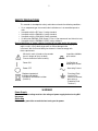
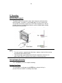
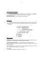
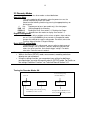
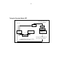
1
User’s
Manual
SR 10
Recorder
User’s Manual
IM 4D8B2-01E
YOKOGAWA
Yokogawa Electric Corporation
IM 4D8B2-01E
2nd Edition
2
Notes :
• The contents of this manual are subject to change without prior notice as a
result of improvements in the instruments performance and functions. Display
contents illustrated in this manual may differ slightly from what actually
appears on your screen.
• Every effort has been made in the preparation of this manual to ensure the
accuracy of its contents. However, should you have any questions or find any
errors, please contact your sales representative.
Disk No. MR32
nd
2 Edition : May 1999(YG)
All Rights Reserved, Copyright © 1998 Yokogawa Electric Corporation
IM 4D82-01E
3
Conventions Used in this Manual
Displayed Characters
Bold alphanumeric characters enclosed with [ ] refer to characters or
setting values are displayed on the screen.
Symbol
The following symbol marks are used to attract the operator’s
attention.
Affixed to the instrument. Indicates danger to personnel or
instrument and the operator must refer to the User’s manual.
ThinUser’s manual to indicate the reference.
Describes precautions that should be observed to prevent injury
or death to the user.
Describes precautions that should be observed to prevent minor
or moderate injury, or damage to the instrument.
Note:
Provides important information for the proper operation of the
instrument.
4
CONTENTS
SAFETY PRECAUTIONS
Using the User Manual
5
6
Chapter 1 Before Operation
1.1 Front/Rear Panels: Functions and Display
1.2 Handling Precautions
7
9
Chapter 2 Daily Operation
2.1
2.2
2.3
2.4
2.5
2.6
Recording
Selecting The Display
Recorder Mode
Loading chart paper
Installing/Replacing pens (Pen Model)
Installing/Replacing the Ribbon
Cassette(Dot Model)
10
11
12
14
16
18
Chapter 3 Maintenance
3.1 Periodic Inspection
3.2 Fuse
19
20
Chapter 4 Troubleshooting
4.1 Error Messages
4.2 Troubleshooting
Index
21
22
5
SAFETY PRECAUTIONS
This recorder is developed to satisfy and to be used under the following conditions:
It is a component type instrument to be installed on an instrumentation panel or
rack.
• It complies with the IEC class II safety standard.
• It complies with the EN61010-1 safety standard.
• It complies with the CSA1010-1 Safety standard.
• It is based on EN55011 (EMI) Group 1, Class A (for commercial and inclustrial use).
• It complies with the EN50082-2 (EMS) safety standard.
General definitions of safety symbols used on the recorder and in this manual:
Make sure to comply with the following safety precautions. Not complying
might result in injury, death of personal, or cause damage to the
instrument. We assume no liability for customer’s failure to comply with
these requirements.
•
Where this mark is found on the recorder
there is danger of injury or death.
Please check the manual carefully.
In-position of bitable
push control
Power ON
Out-Position of
bitable push control
Power OFF
Alternating Current
Equipment protected
throughout by double
insulation or reinforced insulation
(CLASS II)
Functional Earth
terminal(This
terminal should not
be used as a
“Protective Earth
Terminal.”)
WARNING
Power Supply
Ensure the source voltage matches the voltage of power supply before turning ON
the power.
Grounding
Make sure to ground the recorder before turning on the power.
6
Using the Users’s Manual
This manual contains information about the instrument’s functions and
operating producers as well as precautions that should be observed
during use. To ensure proper use of the instruments, please read this
manual thoroughly before operating it. Keep the manual in a safe place for
quick reference whenever the question arises.
Two manuals are provided with the instrument, including this User’s Manual.
Manual Name
User’s Manual
Manual No.
IM 4D8B2-01
Description
Basic Information for recorder
operators.
Technical
Manual
IM 4D8B2-04E
Detailed technical manual
for recorder engineer, including
mounting, wiring and setting
setting Information.
Read this manual first.
Structure of this Manual
1
Chapter Title
Before Operation
2.
Daily Operation
3
Maintenance
4
Troubleshooting
INDEX
Content
Explains basic functions and
display of the encoder and
contains the handling precautions.
Please read carefully.
Contains all Information needed
for simple daily operation of the
recorder, including instructions
on chart, pen and ribbon
cassette replacement.
About periodic inspection and
cleaning of the recorder.
Explains the meaning of some
basic error messages on recorder
display.
7
1.1
Front/Rear Panels: Functions and Display
Front Panel
1. Power Switch (Push-Button Type)
Pressing The Switch Turns The Power ON and OFF.
2. Key Panel (Push Key Type)
The Panel Contains the Following five Keys:
RCD key
Pressing the key starts or stops the recording.
DISP key ESC key
DISP function: Cycles through the modes of display in the order of AUTO,
MANUAL, and OFF. Also selects between the regular settings and operation
modes.
If this key is pressed for 3 sec. The recorders enter in regular setting mode.
ESC function: Exits from the menu in the middle of setting procedures.
Key
Selects setting parameters (numeric or command codes) selecting step
upward circulation.
If the recorder is a pen model, pressing this key for three seconds causes the
recorder to enter the pen-replacement mode.
FEED key, key
FEED Function: The chart is fed as long as this key is being pressed.
Key function: Changes the number of digits for setting the numeric values.
The digit moves from high to low.
CH UP key ENT key
CH UP function: Selects a channel; for which the display shows the screen in
the manual display mode.
Function: Makes a parameter entry or executes a function after selecting
parameters (numerals or command codes.) Pressing the key executes the
settings.
8
3. Chart Cassette: - Contains a Z-fold chart (width 100m, length 16m).
4. Status Display: - RCD indicator: illuminated when recording of measurement values
is in process. ALM indicator: illuminates when an alarm occurs.
5. Seven-Segment Character Display: - Used display data, setting screen, and so on.
•
•
DATA Display (left): Displays the channel no., type of alarm, and measured
data
Setting Screen (right): Displays various settings of the recorder.
Characters on Display
The display consists of seven segments, and therefore characters exist which are
difficult to display. Characters are presened on the display as shown in the following table:
Rear Panel
Below, the rear panel of the dot model recorder, for more details and the rear of the
pen model recorder see the Technical Manual, Section 1.7,and Wiring.
9
1.2
Handling Precautions
Safety Precautions
•
Before you use this recorder make sure to read the safety precautions on
Page No 2 of this module.
•
Do not touch the interior of this recorder. For the replacement of parts, please
contact the dealer of which you purchased the recorder.
•
Turn the recorder power switch OFF as soon as any symptoms of malfunction
such as unusual sound, smell, or smoke yield from the recorder. Also turn the
main power switch off.
If a malfunction occurs, contact dealer from which you purchased the
instrument.
General Handling Precautions
•
The recorder contains many plastic parts. To clean, use a soft, dry cloth. Do
not use chemicals such as benzene or thinner, since this may cause
discoloration or damage.
•
Do not bring any objects charged with static electricity near the signal
terminal. This might cause malfunction.
•
Do not allow any voltage substances to the front or key panel. Do not allow
rubber or vinyl to remain in contact with the recorder for long periods.
•
Whenever the recorder is not used, turn the power switch OFF.
10
2.1 Recording
Switching Power ON/OFF
The power switch is located at the lower right-hand corner of the front face
behind the door. The switch is a push-button type. Press the switch to turn
the recorder ON and Press again to turn OFF. After the power turns ON, the
recorder executes a self-diagnostic check for several seconds before starting
measurement and recording.
NOTE: • The warm-up time is approximately 30 minutes, however, after the initial start-up,
the recorder might need more time.
• If the input wiring is connected parallel with other equipment, do not turn the
power switch ON/OFF to prevent the functions in measuring values.
Starting/Stopping Recording
Press the RCD key to start or stop the recording.
Feeding Chart Paper
The chart paper is fed by pressing the FEED key as long as the key is
pressed. See also section 2.4, Loading Chart Paper.
11
2.2 Selecting the Display
Three different displays can be selected: Manual, and Display OFF. If the DISP key
is pressed you the recorder will change the display modes in the order of
AUTO>MANUAL>OFF,
Note that manual display can’t be selected on the 1-pen model.
Auto Display
Channel No and Measured values will appear on the display. Every Channel will be
shown approximately 2 sec. If the input is gather than the upper limit of the recording span,
------ will appear.
Manual Display
Pen Model: - The Measured values of specified channels are alternately displayed every 2
sec. The contents of the display are the same as that of auto mode.
Dot-Printing Model (Dot Model): - The Measured values of specified channels are
alternately displayed every measurement cycle. The contents of the display are the same as
that of auto mode.
Pressing the CH UP key changes the channel no. Being displayed (Channel No. Increases).
Manual display can’t be selected on the 1-pen model.
Display OFF
Turns OFF all displays except the status Display.
12
2.3 Recorder Modes
The recorder has three modes as described below:
Operation Mode
This is the mode for daily operation; when the power turns on, the
recorder automatically enters this mode.
Select from the following functions by pressing the appropriate keys on
the key panel.
Key
Replacement of pens (pen model only). See chart paper.
RCD Key
Starting/Stopping the recording.
FEED Key
Feeding the chart. See section 2.1, Feeding chart Paper.
DISP Key
Selection from the modes on display. See section 1.1.
Regular Setting Mode
In this mode, daily-used data such as alarm set points, date, and time
are set. Pressing the DISP key three seconds in the operation mode
changes the mode to the regular setting mode. For details, refer to the
Technical Manual Section 2, Regular Settings.
Basic (SETUP) setting Mode
In the basic (SETUP) setting mode, you can adjust a whole range of
detailed settings such as the pen’s position, dot printing position and
colors, the noise input filter, and remot4e trigger settings. For details,
refer to the Technical manual section 3.
Note
• While in the Basic (SETUP) mode, measurement, recording and alarm
detector are not carried out.
• Using the settings function, you can protect your settings by defining a
password when you enter the regular or basic (SETUP) mode. For Details on
the settings Protection Function, see Technical Manual Section 3.12
Turning the Recorder Modes ON
Power On while pressing
the CH UP (ENT) key.
Power ON
Operation
Mode
Regular
Setting mode
Mode changes to the other by pressing
the DISP key for three seconds.
Basic
SET UP mode
Leaving the Basic SET UP mode is
done by the SET UP END procedure.
13
Turing the Recorder Modes OFF
Power ON while pressing
the CH UP (ENT) key
Power ON
QUIT
SET UP
Password
Regular
Setting mode
Operation
Mode
*1
*1
Basic
SET UP model
Password
Leaving the Basic SET UP mode
is done by the SET UP END
* 1 Mode changes to the other by pressing
the DISP key for three seconds.
14
2.4 Loading Chart Paper
Installing/Replacing Chart Paper
1. Open the front door of the recorder, as shown below
2. Make Sure that recording is OFF. Power may be ON.
3. Riffle the chart thoroughly before loading.
4. While gently pressing the chart cassette stoppers, located at both front ends of
the cassette, lift and draw the cassette out of the recorder case.
5. Open the chart retainer backward on the cassette.
6. Pull and open the front transparent chart guide.
15
7. Load the chart paper into the chart compartment; the small perforation
should be at the left hand. Make sure that the sprocket teeth of the chart
drives are properly engaged in the chart paper p[perforations. Take care
not to load the chart paper backwards.
8. Close the chart retainer.
9. Close the chart guide (transparent plastic plate).
10. Replace the chart cassette back into the recorder case; hang the knurls of the
cassette to the grooves of the case, and move the cassette to trap the stopper.
16
11. Press the FEED key on the key panel to assure that the chart moves two or more
folds smoothly into the chart receiver. If it moves unsteadily, do the installing
procedure again from step (4).
NOTE
A red band with a ‘RENEW CHART’ Notice appears when the chart nears to its end
(length of remaining chat is approximately 40 cm) to suggest you to prepare a new chart.
2.5 Installing/Replacing Pens (Pen Model)
•
•
CAUTION
Do not press the felt tip to prevent deformation. Do not move the
penholders up or down scale to protect the driving mechanism.
Always make sure to remove the pen cap before installation.
Simple Replacement
1 Open the front door, and make sure that recording is OFF. Power may be ON.
17
2
Pull and open the display around the hinge.
CAUTION
•
•
Please take care not to apply any undue pressure in an upward or
downward direction to the display, to prevent the strain on the hinges.
Do not force the display open any further than about 1000 from being
closed.
3 Pull out the pen cartridge by pulling the protruding part of the cartridge from the
Pen holder.
Replacement under Pen-Replacement Mode
When a pen is located at a place where its replacement is difficult to do, relocate the
pen by following procedure:
1. Make sure that recording is OFF. The main power switch must be ON.
2. Press the key for three sec. To display [C_Pen] and press the ENT key.
3. Press the key to display [Yes], and press the ENT key. The pens will
move near to the center of the scale where the pens can be easily
replaced.
Note that a line is drawn on the chart when the pens move.
4. Replace the pen according to the ‘simple replacement’ 2, 3 and 4
described above.
5. After pen replacement the indicator shows [End], then press the ENT key.
6. To restart recording, press the RCD key.
18
2.6 Installing/Replacing the Ribbon Cassette (Dot Model)
CAUTION
* Improper cassette insertion may cause faulty print cooler or damage the cassette.
1. Open the front door and make sure that power is switched OFF.
2. Open the display by pulling its left end.
CAUTION
•
•
Please take care not to apply any undue pressure in an upward or
downward direction to the display, to prevent strain on the hinges.
Do not force the display open any further than about 1000 from being
closed.
3. Hold the printer carriage, and moves it to right.
4. Hold the left-hand part of the ribbon cassette, and pull it out from the
recorder case while releasing the cassette holder snap.
19
3.1 Periodic Inspection
Check following items periodically, and replace parts, if necessary.
Character Printing
Are recorded lines or printed characters clear, not blurred? To replace a
felt-tip pen, refer to the User’s manual section 2.6 Installing/Replacing
Ribbon Cassette to replace the ribbon cassette of a dot-printing model.
Chart Paper
Is there enough chart paper left in the chart compartment?
Remaining chart length (cm) is printed on the left margin of the chart at
interval of 20 cm. See also user’s manual section 2.4 loading chart
paper.
Cleaning the carriage shafts (Dot Model)
To maintain proper recording functions, it is recommended to, if
necessary, wipe up dust from the printer carriage with a piece of soft
cloth or paper without fluffing.
20
3.2 Fuse
WARNING
Don’t replace the fuse by yourself. Never take the recorder apart to
replace a fuse.
Please contact you’re nearest Yokogawa sales representative if the
fuse needs to be replaced.
Fuse Rating
Rated Voltage
Rated Current
Type
Approved Standard
: 250V
: 1.25A
: Time lag
: ICE/VDE
21
4.1 Error Massages
Error Code List
Please contact the dealer from which you purchased the recorder in case the
following errors appear. See the Technical Manual, Section 6, for more error
massages.
Error Codes
Meaning
Recovery
Main memory reading error
Main memory writing error
A/D converter memory reading error
A/D converter memory writing error
Calibration data error of A/D converter
System ROM failure
Contact the
dealer from
which you
purchased the
recorder.
System RAM failure
Ribbon shift, ribbon feed failure(dot model).
Printer failure(dot model).
Range memory reading/writing error
System failure.
Attempt replace pen(C_PEn) while
recording.
Stop recording.
22
4.2 Troubleshooting
See the Technical Manual Section 6, for more troubleshooting information.
Recorder is completely inoperative.
Is the power switch
ON? Does the switch
turn properly?
NO
Turn the switch on properly
NO
Contact the supply lines properly.
YES
Is the power supply
properly connected?
YES
NO
Does the power meet
the specified rating?
YES
Contact the dealer from which you
purchased the recorder.
Supply the power with specified
voltage/frequency.
23
INDEX
A
ALM indicator…………………………………………………….
8
B
Basic (SETUP) setting Mode……………………………………
12
C
C_Pen……………………………………………………………..
Carriage Shaft Cleaning (Dot Model)…………………………...
Cassette (Ribbon) Installing/Replacement…………………….
CH UP Key………………………………………………………..
Characters Display……………………………………………….
Copyright……………………………………………………………
17
19
18
7
8
2
D
DISP Key………………………………………………………….
Display
Auto………………………………………………………..
Characters…….…………………………………………..
Manual……….…………………………………………….
Of Status….….……………………………………………
Turning OFF………………………………………………
Dot Printing…..…………………………………………………..
7
11
3
11
8
10
12
E
ENT Key………………………………………………………….
Error Messages………………………………………………….
ESC Key………………………………………………………….
7
6
7
F
FEED Key…………………………………………………………
Feeding Chart Paper…………………………………………….
Functions………………………………………………………….
6
10
7
O
Operation Mode…………………………………………………..
12
P
Pen Model Recorder……………………………………………
Pens, Installing/Reporting (Dot Model)……………………
16,17
8
R
RCD indicator……………………………………………………
RCD Key…………………………………………………………
Rear Panel……………………………………………………….
Regular Setting Mode…………………………………………..
Ribbon cassette, Installing/Replacing…………………………
8
7
7
12
18
S
Safety Precautions……………………………………………
Starting/Stopping Recording…………………………………...
5,9
10
24
YOKOGAWA
Yokogawa Electric Corporation
Headquarters
2-9-32, Nakacho, Mushashino-shi, Tokyo, 180-8750, Japan.
State Headquarters
2-9-32, Nakacho, Mushashino-shi, Tokyo, 180-8750, Japan.
Yokagawa Branch Sales Offices
Nagoya, Osaka, Hiroshima, Fukuoka, Sapporo, Sendai, Ichihara, Toyoda, Kanazava, Takamatsu,
Okayama, and Kitakyusuyu.
Overseas Representative Officers/Service centers
Beijing, Shanghai, (The peoples Republic Of China), Jakarta (Indonesia), Kula Lumpur (Malaysia),
Bangkok (Thailand).
Yokagawa Corporation Of America
Headquarters
2.Dart Road, Newnan, Ga. 30265-1094, U.S.A.
Phone: 1-770-253-7000 Fax: 1-770-251-0029
Branch Sales Officers/ Detroit, Chicago, Los Angeles, Massachusetts, New Jersey, North Carolina,
Oklahoma, Pennsylvania, and Texas.
Yokagawa Europe B. V.
Headquarters
Databankweg 20 Amersfoort 3821 AL, The Netherlands
Phone: 31-334-64-1611 Fax: 31-334-64-1610
Branch Sales Offices/ Wien (Austria), Zaventem (Belgium), Ratingen (Germany), Madrid (Spain),
Runcorn (United Kingdom), Milano (Italy), Velizy Villacoublay (France), Johannesburg (Republic Of
South Africa.)
Yokagawa America Do Sul S.A.
Praca Akapulco, 31, santo amaro, sao Paulo/SP – Brazil
Phone: 55-11-5681-2400 Fax: 65-444-6252
Yokagawa Electric Asia PTE. Ltd
Head Office
5 Bedok South Road, 469270 Singapore
Phone 65-241-3-9933 FAX 65-444-6252
Yokagawa Electric Korea Co. Ltd.
Head Office’
420-5 Chongchon 2dong pupyyong ku lunchon 403-032 Korea
Phone 82-32-510-3107 Fax 82-32-529-6304
Yokogawa Australia PTY. LTD
Head Office (Sydney)
Center court D1 25-27 Paul Street North Ryde NSW 2113 Australia
Phone 61-2-98050699 Fax 61-2-9888-1844
Yokagawa Blue Star Ltd.
Head Office
40-4 leveler Road, Banglore 560001, India
Phone 91-80-2271513 Fax 91-80-2274270
====================================================