1
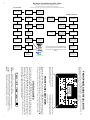
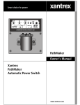
T
Xantrex Technology Inc.
Toll free 1 800 670 0707
Direct 1 604 422 2777
Fax 1 604 420 2145
[email protected]
www.xantrex.com
445-0197-01-01Rev. 1
Printed in the U.S.A.
i4.40
Xantrex
Link 2000-R
Regulator Option
Link 2000-R
Owner's Manual
2
TABLE OF CONTENTS
Front Panel and Status Lights
How the LINK 2000-R Charges
Equalizing Cautions!
Special Setup for the LINK 2000-R
Required Reading
Wiring Instructions
Standby Regulators
Warranty
Troubleshooting Flow Chart
Wiring Diagram
3
4–5
6
7
8
9–15
15
16
18
19
SUPPLEMENT TO THE LINK 2000 OWNER'S MANUAL
THIS DOCUMENT APPLIES TO LINK 2000-R SERIAL NUMBER 5000 AND ABOVE.
The Helping Hand is used to draw your attention to very important sections of this
manual or to indicate items of special interest. Please read these sections carefully.
s
INSTALLERS! THIS DOCUMENT IS IMPORTANT FOR
OPERATION. PLEASE LEAVE IT WITH THE OWNER!
The LINK 2000-R is an integrated battery monitor, inverter/charger
controller, and advanced alternator regulator. This manual pertains
only to the installation, wiring, and testing of the alternator regulator
portion of the system. All other features and functions concerning
monitor operation and Freedom Inverter/Charger operation are
described in the LINK 2000 Owner's Manual (Part number 445-019801-01). You must be familiar with that manual before using the LINK
2000-R.
For use only with externally regulated
12- or 24-volt "P" Field type alternators.
See "Required Reading," page 8.
Notice of Copyright
Xantrex Link 2000-R Battery Monitor © November 2002 Xantrex International. All rights reserved. Xantrex is a registered
trademark of Xantrex International.
Disclaimer
UNLESS SPECIFICALLY AGREED TO IN WRITING, XANTREX TECHNOLOGY INC. (“XANTREX”)
(a) MAKES NO WARRANTY AS TO THE ACCURACY, SUFFICIENCY OR SUITABILITY OF ANY TECHNICAL OR
OTHER INFORMATION PROVIDED IN ITS MANUALS OR OTHER DOCUMENTATION.
Email: [email protected]
(b) ASSUMES NO RESPONSIBILITY OR LIABILITY FOR LOSS OR DAMAGE, WHETHER DIRECT, INDIRECT,
CONSEQUENTIAL OR INCIDENTAL, WHICH MIGHT ARISE OUT OF THE USE OF SUCH INFORMATION. THE USE
OF ANY SUCH INFORMATION WILL BE ENTIRELY AT THE USER’S RISK.
Date and Revision: November 2002, Revision 1
Part Number: 445-0197-01-01
Contact Information Web: www.xantrex.com
Phone: 1 800 670 0707 (toll free in North America) 1 604 422 2777 (direct) Fax: 1 604 420 2145
19
18
Regulator Troubleshooting Flow Chart
Most regulation problems can be solved with the following flow chart
Terminals #1 through #10 are on the Monitor Terminal Board.
Wires referred to by color are in the wiring harness for the Ideal Regulator Output Module
NO OUTPUT
Do final progress
& startup test
described on page 14
OK
No or variable
alternator current
Check
alternatorbelts, field
wire,alternator
ground, & field gnd.
Is the Red CHG
LED on the Output
Module lit?
Is the wiring harness
from the Output
Module pluged in
correctly
HIGH VOLTAGE
FAIL TEST
Is the green ON LED
located on the
Output Module lit?
YES
YES
YES
Voltage OK, problem
in alternator. If not
OK, problem in wire
or connections.
Check for voltage at
the alternator end of
the blue field wire.
Should be 10 to 12V.
HIGH VOLTAGE,
REGULATOR NOT
IN CONTROL.
NO
NO
Is there 12V between
the black wire and
the brown wire REG
ON?
Is the Charge Cycle
status light lit on the
front panel of the
meter?
NO
YES
Alternator shunt sense
leads reversed and
current > 100.
Reverse sense leads.
Is there 12V between
black & red wires, if
not check fuse
supplying red wire
LIT
With engine off
make sure the
Green LED REG
ON is not lit.
NO
NOT LIT
Output Module is
bad. Replace it.
Is phone cord between
Monitor Board and
Output Module
plugged in correctly?
Is the oil pressure
switch jumpered or
the key turned on?
YES
Disconnect the
brown REG ON
wire, is the RED
LED still lit?
YES
Is the Red CHG LED
Output Module lit?
NO
YES
Check circuit
supplying the switch
(fuse & wire).
Is there about 5V
between term #1 and
the test point shown
on the Monitor TB?
If voltage is OK
problem is with
Monitor Terminal
board, replace it.
Is there about 5V
between term #1 and
the test point shown?
YES
Problem in ribbon
cable or meter. Try replugging cable
If not OK call us.
The problem is in
the alternator or the
external wiring.
NO
Be sure set up correct
for your battery
system. Is Bat#2
defeated? See manual.
NO
YES
Use this flow chart to assist in troubleshooting if
you encounter unexpected results during installation, start up, and operation of your new LINK
2000-R
NO
If there is no voltage
the problem is in the
phone cord or
connections.
Check battery voltage
sense leads. Do
progress test #1.
If alternator was
converted from
internal reg. was
diode trio removed?
FRONT PANEL AND STATUS LIGHTS
i4.40
Selecting TIME when the alternator regulator
is operating displays the alternator output
current. The current is displayed with an "A"
preceding the value.
The front panel operation of the LINK 2000-R is exactly the same as described in the
LINK 2000 owner's manual, with the exceptions noted below.
Status lights indicate which cycle the regulator
(and/or the charger) is in. The AC light will be
OFF if there is no external AC input.
FRONT PANEL SWITCHES
The operation of the front panel is the same as the LINK 2000 with the exception of the
TIME switch. When the alternator regulator is on (REG ON energized) and TIME is
A".
selected, the alternator output current is displayed. It is preceded with the character "A
For example, an alternator output current of 100 amps would be displayed as AI00.
STATUS LIGHTS
The status lights on the front of LINK 2000-R use LEDs (light-emitting diodes) to indicate
which cycle the alternator regulator is in during charging. The meaning of the lights is the
same as described in the LINK 2000 installation manual. The only difference is that when
there is no external AC power available, and the regulator is turned on, the status lights
indicate the charge cycle for the alternator regulator. If external AC power is available, the
charger is turned ON, and the alternator is also charging the battery, the status lights indicate
the cycle of both the charger and the alternator regulator.
AC IN:
Green LED on when AC is present.
CHARGE: Red LED on when charger/alternator is in bulk CHARGE Cycle.
Flashes Red LED when charger/alternator is in EQUALIZE Cycle.
ACCEPT: Orange LED on when charger/alternator is in ACCEPTANCE Cycle.
FLOAT: Green LED on when charger/alternator is in FLOAT Cycle.
3
4
HOW THE LINK 2000-R CHARGES
See page 18 of LINK 2000 manual for details of the Ideal Charge Curve.
Warning: Limitations On Use
Please refer to your product user manual for limitations on uses of the product. Specifically, please note that the Link 2000-R is not
intended for use in connection with life support systems and Xantrex makes no warranty or representation in connection with any use of
the product for such purposes.
Return Material Authorization Policy
Before returning a product directly to Xantrex you must obtain a Return Material Authorization (RMA) number and the correct factory
“Ship To” address. Products must also be shipped prepaid. Product shipments will be refused and returned at your expense if they are
unauthorized, returned without an RMA number clearly marked on the outside of the shipping box, if they are shipped collect, or if they are
shipped to the wrong location.
The serial number of your product
Information about the installation and use of the unit
Information about the failure and/or reason for the return
A copy of your dated proof of purchase
When you contact Xantrex to obtain service, please have your instruction manual ready for reference and be prepared to supply:
•
•
•
•
Return Procedure
2.
1.
3.
Package the unit safely, preferably using the original box and packing materials. Please ensure that your product is shipped fully insured
in the original packaging or equivalent. This warranty will not apply where the product is damaged due to improper packaging.
Include the following:
•
The RMA number supplied by Xantrex Technology Inc clearly marked on the outside of the box.
•
A return address where the unit can be shipped. Post office boxes are not acceptable.
•
A contact telephone number where you can be reached during work hours
•
A brief description of the problem
Ship the unit prepaid to the address provided by your Xantrex customer service representative.
TURNING THE REGULATOR ON
The regulator is turned on by supplying 12 V or 24 V to the REG ON (brown
wire) terminal. It must have power only when the engine is running. See page 13.
If you are returning a product from outside of the USA or Canada
In addition to the above, you MUST include return freight funds and are fully responsible for all documents, duties, tariffs, and deposits.
If you are returning a product to a Xantrex Authorized Service Center (ASC)
A Xantrex return material authorization (RMA) number is not required. However, you must contact the ASC prior to returning the product
or presenting the unit to verify any return procedures that may apply to that particular facility.
CHARGE CYCLE
Behavior: Alternator current at maximum and battery voltage increasing.
The Charge Cycle ensures fast charging without alternator overload. The
alternator current limit will not be exceeded. The FIELD output is varied to hold
the alternator at its current limit until the acceptance voltage is reached. When the
acceptance voltage has been attained by either battery, the Acceptance Cycle begins.
RAMPING UP
Behavior: Output of alternator increases over a 20-second period.
Ramping up the alternator output avoids shock-loading the belts with full
alternator output. The output on the FIELD terminal is increased over a 20-second
period until the alternator current limit (default value 100 A) is reached. The Charge
Cycle now begins. If the acceptance voltage is reached before the current limit,
the Acceptance Cycle begins.
DELAY START-UP
Behavior: No output on the Field terminal (blue wire).
Two-second delay allows time for the engine to start.
1) Terminal references for the Ideal Regulator Output Module.
2) Voltage values given are for 70 °F and liquid lead-acid batteries.
The LINK 2000-R uses the Ideal Regulator Output Module to control the alternator
to conform to the Ideal Charge Curve’s four defining cycles; Charge, Acceptance, Float,
and Equalize. The following discusses details of each of the cycles.
NOTES:
CYCLE
STATUS
LIGHT
RED
LED ON
ORANGE
LED ON
ACCEPTANCE CYCLE
Behavior: Battery amps falling, voltage at 14.4 V for 12 V systems, 28.8 for
24 V. (Voltage depends on battery type and ambient temperature settings.)
The Acceptance Cycle guarantees thorough charging by continuing to charge
the battery until the charging current becomes a small percentage of battery
capacity (2% default). The alternator output is varied to maintain the battery at
the acceptance voltage. During the Acceptance Cycle the alternator current limit
will not be exceeded even if a heavy load is placed on the system.
When the batteries have reached the acceptance voltage and the current is
below 2%, the Acceptance Hold Cycle begins. If the Acceptance Cycle has lasted
3.5 hours, the Float Cycle begins, even if the charged parameters have not been
met. If the voltage of either battery falls below the acceptance voltage for more
than two minutes, the Charge Cycle starts again.
17
16
LIMITED WARRANTY
What does this warranty cover?
This Limited Warranty is provided by Xantrex Technology, Inc. (“Xantrex”) and covers defects in workmanship and materials in your
Xantrex Link 2000-R. This warranty lasts for a Warranty Period of 12 months from the date of purchase at point of sale to you, the
original end user customer.
This Limited Warranty is transferable to subsequent owners but only for the unexpired portion of the Warranty Period.
What will Xantrex do?
Xantrex will, at its option, repair or replace the defective product free of charge, provided that you notify Xantrex of the product defect
within the Warranty Period, and provided that Xantrex through inspection establishes the existence of such a defect and that it is covered
by this Limited Warranty.
Xantrex will, at its option, use new and/or reconditioned parts in performing warranty repair and building replacement products. Xantrex
reserves the right to use parts or products of original or improved design in the repair or replacement. If Xantrex repairs or replaces a
product, its warranty continues for the remaining portion of the original Warranty Period or 90 days from the date of the return shipment
to the customer, whichever is greater. All replaced products and all parts removed from repaired products become the property of Xantrex.
Xantrex covers both parts and labor necessary to repair the product, and return shipment to the customer via a Xantrex-selected nonexpedited surface freight within the contiguous United States and Canada. Alaska and Hawaii are excluded. Contact Xantrex Customer
Service for details on freight policy for return shipments outside of the contiguous United States and Canada.
How do you get service?
If your product requires troubleshooting or warranty service, contact your merchant. If you are unable to contact your merchant, or the
merchant is unable to provide service, contact Xantrex directly at:
Phone: 1 800 670 0707 (toll free in North America) 1 604 422 2777 (direct)
Fax: 1 604 420 2145
Email: [email protected]
Direct returns may be performed according to the Xantrex Return Material Authorization Policy described in your product manual. For
some products, Xantrex maintains a network of regional Authorized Service Centers. Call Xantrex or check our Web site to see if your
product can be repaired at one of these facilities.
In any warranty claim, dated proof of purchase must accompany the product and the product must not have been disassembled or modified
without prior written authorization by Xantrex.
The dated purchase receipt from the original purchase of the product at point of sale to the end user, or
The dated dealer invoice or purchase receipt showing original equipment manufacturer (OEM) status, or
The dated invoice or purchase receipt showing the product exchanged under warranty
Proof of purchase may be in any one of the following forms:
•
•
•
What does this warranty not cover?
This Limited Warranty does not cover normal wear and tear of the product or costs related to the removal, installation, or troubleshooting
of the customer’s electrical systems. This warranty does not apply to and Xantrex will not be responsible for any defect in or damage to:
a) the product if it has been misused, neglected, improperly installed, physically damaged or altered, either internally or externally,
or damaged from improper use or use in an unsuitable environment;
b) the product if it has been subjected to fire, water, generalized corrosion, biological infestations, or input voltage that creates
operating conditions beyond the maximum or minimum limits listed in the Xantrex product specifications including high input
voltage from generators and lightning strikes;
the product if repairs have been done to it other than by Xantrex or its authorized service centers (hereafter “ASCs”);
the product if it is used as a component part of a product expressly warranted by another manufacturer;
the product if its original identification (trade-mark, serial number) markings have been defaced, altered, or removed.
c)
d)
e)
Disclaimer
Product
THIS LIMITED WARRANTY IS THE SOLE AND EXCLUSIVE WARRANTY PROVIDED BY XANTREX IN CONNECTION WITH
YOUR XANTREX PRODUCT AND IS, WHERE PERMITTED BY LAW, IN LIEU OF ALL OTHER WARRANTIES, CONDITIONS,
GUARANTEES, REPRESENTATIONS, OBLIGATIONS AND LIABILITIES, EXPRESS OR IMPLIED, STATUTORY OR OTHERWISE
IN CONNECTION WITH THE PRODUCT, HOWEVER ARISING (WHETHER BY CONTRACT, TORT, NEGLIGENCE, PRINCIPLES
OF MANUFACTURER’S LIABILITY, OPERATION OF LAW, CONDUCT, STATEMENT OR OTHERWISE), INCLUDING WITHOUT
RESTRICTION ANY IMPLIED WARRANTY OR CONDITION OF QUALITY, MERCHANTABILITY OR FITNESS FOR A
PARTICULAR PURPOSE. ANY IMPLIED WARRANTY OF MERCHANTABILITY OR FITNESS FOR A PARTICULAR PURPOSE TO
THE EXTENT REQUIRED UNDER APPLICABLE LAW TO APPLY TO THE PRODUCT SHALL BE LIMITED IN DURATION TO
THE PERIOD STIPULATED UNDER THIS LIMITED WARRANTY.
IN NO EVENT WILL XANTREX BE LIABLE FOR ANY SPECIAL, DIRECT, INDIRECT, INCIDENTAL OR CONSEQUENTIAL
DAMAGES, LOSSES, COSTS OR EXPENSES HOWEVER ARISING WHETHER IN CONTRACT OR TORT INCLUDING WITHOUT
RESTRICTION ANY ECONOMIC LOSSES OF ANY KIND, ANY LOSS OR DAMAGE TO PROPERTY, ANY PERSONAL INJURY, ANY
DAMAGE OR INJURY ARISING FROM OR AS A RESULT OF MISUSE OR ABUSE, OR THE INCORRECT INSTALLATION, INTEGRATION OR OPERATION OF THE PRODUCT.
Exclusions
If this product is a consumer product, federal law does not allow an exclusion of implied warranties. To the extent you are entitled to
implied warranties under federal law, to the extent permitted by applicable law they are limited to the duration of this Limited Warranty.
Some states and provinces do not allow limitations or exclusions on implied warranties or on the duration of an implied warranty or on the
limitation or exclusion of incidental or consequential damages, so the above limitation(s) or exclusion(s) may not apply to you. This
Limited Warranty gives you specific legal rights. You may have other rights which may vary from state to state or province to province.
ORANGE
LED ON
GREEN
LED ON
RED
LED
FLASH
ACCEPTANCE HOLD CYCLE
Behavior: Voltage at 14.4 V (28.8 V for 24 V), battery amps below 2%.
The Acceptance Hold Cycle ensures that the battery has accepted as much
charge as it can. During the Acceptance Hold Cycle the charged voltage is
maintained and charging current is monitored. Both the charged voltage and the
charged current % must continue to be satisfied for 10 minutes for the Acceptance
Hold Cycle to end. The Acceptance Hold Cycle is also terminated after 20
minutes from its beginning even if the battery current has not stayed below the
charged current for the entire time.
If the voltage of the batteries falls below the charged voltage for more than two
minutes, the Charge Cycle starts again.
FLOAT CYCLE
Behavior: Battery amps below 2%, voltage constant at 13.5 V (27 V FOR
24 V). (Voltage depends on battery type and ambient temperature setting.)
During the Float Cycle the float voltage is maintained. The alternator will
supply up to its current limit to maintain the float voltage and supply DC loads.
RESTARTING THE CHARGE CYCLE
MANUALLY: The Ramp Up Cycle may be manually restarted by turning off
the REG ON terminal and turning it back on again. This will require you to turn
off the key switch supplying REG ON or shutting off and restarting the engine
if REG ON is supplied by an oil pressure switch.
AUTOMATICALLY: The Charge Cycle is automatically restarted if the
voltage of the battery being charged drops 0.2 V (0.4 V for 24 V) below the float
voltage (0.3 V when charging with the inverter/charger) for more than two minutes.
EQUALIZE CYCLE
Behavior: Battery amps constant at 4%, voltage is rising to a maximum
of 16.0 V when charging with the alternator and 16.3 V when charging with
the inverter/charger. (Limited to acceptance voltage for gelled batteries.)
To start the Equalize Cycle press the SETUP BUTTON for five seconds until
the LED begins to flash. Now press both the VOLTS and the A hrs BUTTON
simultaneously. Hold them both down for five seconds until the red CHARGE
LED begins to flash and the “E” in the display goes out. To terminate the Equalize
Cycle and force the system into the float cycle, repeat the same procedure. The
cycle automatically terminates 3.5 hours after initiation, or when the current drops
to 2% of capacity at 16.0 V. (Equalize terminated in eight hours if using the
inverter/charger.)
The Equalize Cycle is a controlled overcharge to remove lead sulfate that is
not removed during normal charging. Liquid batteries should be equalized about
every 30 days when in deep cycling service.
5
6
EQUALIZING CAUTIONS!
Neither the GREEN or the RED LED should be ON when the engine
is off! If the RED LED is ON, and the green LED (labeled "ON") is OFF, it is an
indication that the FET is shorted or the field is connected to some other source.
DO NOT OPERATE THE SYSTEM UNTIL THIS IS RESOLVED!
It is now time to start up the engine and see how everything works. For this test
make sure the battery charger or any other charging sources are turned off.
Partially discharge the batteries (remove at least 20% of the capacity—it may take a few
hours at a relativity high discharge rate). Start the engine and watch the battery voltage to
see that it raises to and levels off at about 14.4 (28.8) volts in the Acceptance Cycle. With
the default values, when the battery current falls to about 4 amps (2% of the battery capacity)
the regulator will shift into the Float Cycle and maintain the batteries at the Float voltage.
Also check the alternator current by pressing the TIME button and using a milliVolt meter
to measure the voltage drop across the alternator shunt and comparing it to the reading on
the LINK 2000-R. The milliVolt reading multiplied by ten should about equal the LINK
2000-R alternator current reading. The alternator current measurement is inherently less
accurate than the battery current measurement—you may see up to + 3 amps error.
Turn off sensitive electronics before equalizing.
Equalizing causes the battery to gas. You should check the battery electrolyte
before and after equalization. Do not over-fill before equalization as the electrolyte may
expand and cause it to flow over the tops. You should be present during this type of
charging. Hydrogen and oxygen gas is generated during equalization. Make sure
there is adequate ventilation.
Batteries should not be equalized every charge/discharge cycle. Normally, the
battery is cycled between 50% charged and the 85% to 95% charged level reached by
the normal Charge and Acceptance Cycle. Every 30 days, though, the batteries should
be equalized to regain full capacity and extend life.
To equalize, first go through a complete Charge and Acceptance Cycle. Check the
electrolyte level, but do not overfill. Re-check and top off the electrolyte after equalizing.
Remember, equalizing is constant current charging with a small regulated
current that permits a higher maximum voltage. The goal is to use a small current
and gradually let the battery rise to its maximum voltage.
STANDBY REGULATORS
Install and test your standby regulator or any other spares you might carry
before cruising!
Part of our power system design philosophy is to consider spares and backup
systems before they are needed. We have designed the Ideal Regulator with this in
mind. The Ideal Regulator Output Module wiring harness is compatible with standard PField external regulators. Simply carry a spare regulator that is plug compatible and
just unplug the Output Module and plug in your standby regulator. You may use a simple,
adjustable, constant voltage regulator or we would suggest that you consider the Xantrex
Incharge Regulator, which provides three-stage charging, plug compatibility, and is fully
adjustable.
EQUALIZING GELLED BATTERIES
Gelled batteries are not normally equalized. However, if the battery has been
severely discharged, the voltage of the battery may easily reach the acceptance level
with a very small current. In fact, the current may be less than the 2% required to terminate the Acceptance Cycle. This can cause the system to believe that the battery is full
and switch to the Float Cycle. Equalization may be the only way to get the battery to
accept a charge. Be sure that the battery TYPE # is set to #1 or #2 before using this
cycle on gelled batteries. The equalization voltage is limited to the acceptance
voltage but the cycle lasts for 3.5 hours. (Eight hours if using the Freedom charger.)
Please consult your battery manufacturer regarding the appropriateness of this cycle
for their batteries.
15
14
ASHA TERMINAL (alternator shunt alternator side)
YELLOW WIRE must be terminated on the small screw on the alternator side of
the alternator shunt. This wire should be connected exactly as described to ensure proper
operation. Since this wire is at battery voltage it should be protected with a 2-amp fuse at
the shunt as shown; install the fuse after the wiring is connected. No other wires should be
connected here.
FINAL TEST AND ENGINE STARTUP
Do this test with the engine OFF!
If you cannot pass this test do not start the engine!
This is the final checkout. Plug the 8 conductor data cord (the larger of the two
phone cords) into the Monitor Terminal Board and the Regulator Output Module. Check
the battery amps—you should see the same low number as in PROGRESS CHECK #2.
The green ON LED on the Ideal Regulator Output Module must be off.
Now we want to simulate the engine running, so turn on the regulator by turning the
key switch to the ON position, or if normally open oil pressure switch is used, jumper
together its two terminals. For this test only we want to supply voltage to the REG ON
terminal while the engine is off. The GREEN ON LED should be ON. The red Charge Cycle
Status light on the Link 2000-R front panel should also be ON. The RED CHG LED on
the Output Module, which indicates that field voltage is being supplied, should gradually
increase in brightness during the next 30 seconds. Also check the TIME function
which should display "a000" indicating the alternator output current is zero.
To verify that current is actually flowing into the alternator field use the LINK
2000-R to check the number of amps flowing from whichever battery has been selected
by the main battery switch. You should see -3 to -5 amps of current flowing. This current
is being supplied to the alternator field, and perhaps, to other instrumentation that is also
turned on with the key switch if you are not using an oil pressure switch.
To verify that it is the alternator field consuming the current, turn off the power
to the REG ON terminal and disconnect the FIELD wire from the alternator field. Repeat
the test. The current should now be about 2 to 4 amps less than it was. This test assures
you that the regulator is supplying the field current.
Another easy way to test if the field is energized is to check the magnetism of the
rotor by touching the end of the alternator shaft with a steel screwdriver. Do it with the
regulator turned on (wait 20 seconds for ramp-up cycle) and with it turned off—there
should be a noticeable difference. If you cannot pass this test see the troubleshooting
flow chart. If you still need help, call your dealer or Xantrex Technology Inc.
SPECIAL SETUP FOR LINK 2000-R
The following is a list of special setups that may be necessary to tailor the LINK 2000-R to
your system. Please see pages 10–14 of the LINK 2000 Owner's Manual for details on
how to use the FUNC mode.
F10 - ALTERNATOR CURRENT LIMIT
DEFAULT = 100
RANGE = OFF, 30–220 AMPS
STEP = 10 A
This function is only used with the Link 2000-R (Alternator Regulator Model). It sets
a safety current limit for the alternator. This limits the maximum amount of current that the
alternator can deliver which in turn reduces heat and wear on belts and bearings. This value
is reset to 100 amps in the event of a reset to factory default values.
CAUTION: OFF defeats this safety feature and the alternator will be run at
full output until the Acceptance Voltage is reached. You can also use this feature
to troubleshoot the alternator current measuring/limiting feature.
F11 - BATTERY #2 USED FOR CONTROL
DEFAULT ON = BATTERY #2 USED FOR CONTROL
OFF = BATTERY #2 IS NOT USED FOR CONTROL
This function is used to defeat Battery #2 as a part of the charger and alternator
regulator control functions of the Link 2000-R. This is necessary for systems that have
both 12 V and 24 V batteries. Battery #1 must be the battery that is used by the Freedom
Inverter (or charged by the alternator when controlled by the Link 2000-R). You may also
wish to use this function if the main house battery (Bank #1) is substantially larger than
a separate engine battery (Bank #2) that is also monitored by the Link 2000-R. This will
prevent the Link 2000-R from making a premature transition to float based on the smaller
engine battery meeting the charged parameters substantially before the house battery.
NOTE: Function F11 is not changed in a reset to factory default values. If you
wish to change this function you must use the setup routine to change it.
7
8
REQUIRED READING
1) Read the REQUIRED READING section of the LINK 2000 owner's manual.
2) All wiring to the terminal board should be #16 AWG (#14 may be used).
The same 8 wire twisted pair cable recommended in the LINK 2000 manual may
3)
be used for the LINK 2000-R. The wiring diagram is color coded to this cable.
CAUTION! YOU MUST READ THIS SECTION!
4) The LINK 2000-R Ideal Regulator Output Module is designed to replace external "P"
type regulators. If your alternator is internally regulated, modification will be necessary. The
LINK 2000-R is not designed to regulate N-type alternators; that is, alternators that require
regulation by switching in the negative supply to the field. This includes most Japanese and
internally regulated alternators. If these alternators are to be converted to external regulation
you must disconnect the internal regulator and the diode trio in the alternator. This
should be performed by a qualified alternator shop. The warranty does not cover the
alternator, batteries, or any other devices, or equipment in the system. An
improperly converted alternator may cause damaging high voltages. Please be sure
to check the regulation voltage during initial operation to verify that the LINK 2000-R
is in control of the system.
5) The LINK 2000-R is designed to regulate alternators up to 230 amps, provided that
the field current does not exceed 10 amps total. It can also regulate two alternators in parallel,
charging the same battery, if they are the same size with a combined total capacity of less
than 230 amps, and combined field current less than 10 amps. If the alternators are on
different engines you must install a normally open oil pressure switch, or a relay activated
by the key switch, in series with the field of each alternator to avoid supplying field current
to an alternator whose engine is not running.
6) The alternator shunt is in series with the alternator output and carries the full alternator
current. The brass portions of the shunt are at +12 V (24 V) potential and should therefore
be protected from accidental contact to grounded objects or battery negative.
If a small alternator is being replaced by a high output alternator you must increase
7)
the size of the alternator wiring. Use the table below to find the appropriate wire size. The
total length of both the positive and negative runs must be measured.
ALTERNATOR MAXIMUM OUTPUT
CABLE SIZE (AWG)
10 FT OR LESS 11 TO 20 FT
35 A
#8
#8
60 A
#6
#4
75 A
#6
#4
100 A
#4
#2
130 A
#4
#1
170 A
#2
#1/0
200 A
#1
#2/0
8) Battery temperature should never exceed 120 °F. We recommend a 110 °F limit.
FIELD WIRE TERMINAL
BLUE WIRE is connected to the FIELD TERMINAL on the back of the alternator
and supplies alternator field current. The gray insulated plug connector may be plugged
directly into standard small case high output alternators. (NOTE: The white wire that is
stubbed out of the gray plug is for electronic tachometers and has no function related to
alternator regulation.) If the plug will not fit into the alternator it may be cut off and the blue
wire may be terminated with an insulated spade terminal or other appropriate connection
for the alternator field terminal on the alternator. (The RED LED, on the Ideal Regulator
Output Module, labeled CHG indicates field voltage is present on this BLUE WIRE. The
RED LED glows more brightly as the alternator output increases.)
CAUTION: The gray plug will fit into the typical DELCO internally regulated
alternator but the internal regulator must first be disabled. DO NOT attempt to use the
Link 2000-R with an internally regulated alternator without modifying it to use
external regulation! See #4 on page 8.
REG ON TERMINAL
BROWN WIRE supplies the voltage that turns on the Ideal Regulator Output
Module. It should be connected to a normally open oil pressure switch, or some other
switch (such as an ignition switch or relay), that is hot (+12 V / 24 V) when the engine is
running and off when the engine is off. If the system has a battery isolator, or separate
engine starting battery, the BROWN WIRE should be supplied from a stable 12 V / 24 V
source. This wire must not be connected to the oil pressure sensor for the oil pressure
gauge or to the oil pressure switch for the alarm system. A separate NORMALLY OPEN
oil pressure switch should be used. When this wire is energized the GREEN LED labeled
ON is lit.
The GREEN LED must be OFF when the engine is off! If the regulator is left
continuously ON it may destroy the Ideal Regulator Output Module, damage the
alternator, discharge the battery, and cause system failure.
+12 V/24 V TERMINAL
RED WIRE is the +12 V / 24 V supply. It is shown connected to the alternator
side of the alternator shunt (ASHA). Connecting it here ensures a stable voltage with little
voltage drop to supply the alternator field power. The 10-amp fuse shown should be
installed to protect the wiring.
If an isolator is in the system, the +12 V / 24 V (Red wire) must connect to the
battery side of the isolator.
GND (GROUND) TERMINAL
BLACK WIRE wire is power ground. It is connected to the alternator ground.
ASHB TERMINAL (alternator shunt battery side)
GREEN WIRE must be terminated on the small screw on the battery side of
the alternator shunt. This wire must be connected exactly as shown. Since this wire is
at battery voltage it should be protected with a 2-amp fuse at the shunt as shown;
install the fuse after the wiring is connected. No other wires should be connected here.
13
12
TERMINAL #10
YELLOW WIRE (B2SHB), is connected to the SMALL SCREW ON THE
BATTERY SIDE of the Battery #2 shunt (B2SHB). The TERMINAL #10 YELLOW
WIRE and TERMINAL #9 BROWN WIRE should be a twisted pair.
PROGRESS CHECK #2
Now it is time to check the battery current function. Plug the meter's ribbon cable into the
Monitor Terminal Board and/or insert the fuses. Turn off all DC loads and charging sources.
With everything off select Battery #1 or #2 Amps—the LINK 2000-R should read 0.0,
-0.0, or no more than -0.1 A. (The meter uses less than 0.1 A.) If there is a larger current
draw it normally means that not all the DC loads are turned off. There may be an alarm
system, a clock, or other instrumentation that is left on all the time intentionally. That is
okay as long as you find each load and decide that it is an acceptable continuous current
draw. Once your base-line current is known, remember it. If you cannot always turn off loads
and reach the same number of amps you should find out why. Turn on various loads and
make sure there is a minus sign in front of the display which indicates discharge. If the
number has no minus sign and there are no charging sources on, it means that the battery
shunt sense leads are reversed. If you have a problem call your dealer or Xantrex
Technology Inc. The wiring is now complete and the battery monitoring functions of the
meter now are fully operational.
The battery monitoring and inverter/charger functions of the LINK 2000-R may be
operated independently of the alternator regulator functions. Simply unplug the 8 conductor
data cord (described in the next section) between the Monitor Terminal Board and the Ideal
Regulator Output Module to disable the regulator. The alternator will freewheel harmlessly.
IDEAL REGULATOR OUTPUT MODULE WIRING
MOUNTING THE OUTPUT MODULE
The Ideal Regulator Output Module may be located anywhere convenient to the
alternator that is not subject to salt or fresh water spray. The components in this module
have been coated to resist corrosion but are not immune to, nor warranted against, abuse.
This module has on it the FET (field effect transistor) that actually does the work of
supplying power to the alternator field. While the reliability of this module is very high
it also does all of the real work. The system has been designed with on-site repairability
in mind, a spare Output Module or a standby regulator should be considered for longdistance cruising.
The harness that is supplied with this module is a standard alternator harness. It
is keyed so that it cannot be improperly plugged into the module. The colors mentioned
below correspond to the color code of the wiring harness. There is also a 25-foot 8
conductor data cord supplied to interconnect the Monitor Terminal Board and the Ideal
Regulator Output Module. The following discusses each of the wires connected to the
Ideal Regulator Output Module beginning from the left side of the module.
i4.40
WIRING INSTRUCTIONS
Refer to the wiring diagram while using these instructions.
7) Eight Conductor Data Cord: This 25' long cord
connects the Monitor Terminal Board to the Ideal
Regulator Output Module. This is the larger of the
two cords.
These two cords are not interchangeable.
6) Four Conductor Remote Cord: This 25' long
phone cord connects the LINK to the inverter/charger.
This is the smaller of the two cords.
5) The Alternator Shunt: Single 500 A,
50 mV shunt used to measure current
flowing out of the alternator.
4) The Monitor Terminal Board: The
wiring for battery monitoring terminates
here. The ribbon cable from the meter
plugs into this board. It also has a RJ-45
jack on it for the Ideal Regulator Module.
There are several components to LINK 2000-R METERS:
1) The LINK 2000-R
Meter: Contains the microprocessor and display. The
actual regulation program is
in the meter. It is terminated
with a ribbon cable. It also has
a RJ-11 jack for the remote
cord to the inverter/charger.
2) The Ideal Regulator
Output Module: Supplied
with a harness that connects
to the alternator. There is
also a RJ-45 jack and plugs
for the alternator shunt wiring
and red and green indicator
lights used for troubleshooting.
3) The Battery Shunt: Dual
500 A, 50 mV shunt used to
measure current flowing in or
out of the batteries.
Our Customer Service Manager says, "Be a genius—ensure a
successful installation by following our wire-by-wire instructions
and please do the two progress checks and the final startup test."
Be sure the battery shunt is installed before proceeding.
MONITOR BOARD INSTALLATION & WIRING
MOUNTING THE MONITOR TERMINAL BOARD
The Monitor Terminal board should be secured behind or adjacent to the meter. It
should be accessible and easy to see during hookup. The meter comes standard with an
18" ribbon cable.
Wiring is simplified by using our custom multiple conductor twisted pair cable
available from your dealer. See LINK 2000 manual. If you supply your own cable we
recommend 16 AWG. Larger wire is okay but not necessary. Do not use larger than #14
AWG, as it will make terminating the wires difficult. Use twisted pairs where specified. Use
the same color scheme as on the schematic to facilitate troubleshooting if required.
Begin hooking up from the bottom (terminal #1 ) of the terminal strip toward
the top.
9
10
TERMINAL #1
BLACK WIRE (AGND) is the Analog Ground. It is the reference for all
measurements. It must be connected on the BSHG (Grounded) side of the battery shunt.
The BSHG side of the shunt is the side opposite of the negative battery terminals. It must
have a good connection to one of the two #10 screws on the top of the battery shunt.
Do not connect anything else to this terminal.
TERMINAL #2 is not used.
TERMINAL #3
WHITE WIRE (LITE) turns on the monitor backlighting. It may be supplied from
a switch that controls other instrument lighting or it may be connected to TERMINAL #4
if you wish the lighting to be on all the time. Set at the default value the backlighting consumes
about 8 mA (0.008 A). If left on all the time it would use less than 0.2 Ah per day.
TERMINAL #4 <<Consider the options for this wire>>
RED WIRE (12 / 24 V) is the +12 V / 24 V power to supply the meter. The wiring
diagram shows two options. The preferred option is to jumper together TERMINALS
#4 and TERMINAL #5 as shown. Wired this way, the meter cannot accidentally be
de-powered. It has the disadvantage of always consuming a little bit of power from the
#1 Battery. The meter consumes about 28 mA (0.028 A). If left on all the time it would use
about 0.7 Ah per day.
If the system is left on for long periods (long enough to significantly discharge the
battery) with no charging sources available, then you should consider the option shown with
the dotted line. In this case the TERMINAL #4 RED WIRE is not jumped to the
TERMINAL #5 BLUE WIRE but supplied from the common of the battery switch. (Be
sure to install the 2 A fuse as near the battery switch as possible.) Then, whichever battery
is selected by the battery switch is the battery that supplies the power for the meter.
Caution: With this option, if the battery switch is turned off, the meter is de-powered
and this resets amp hours to zero. Therefore the battery switch should never be turned off
except when leaving the system for a long period of time. When the system is returned to
service you must resynchronize the meter by fully charging the battery.
Another option for the TERMINAL #4 RED WIRE is to install a separate on/off
switch in it before it connects to the terminal board. Just remember to turn off the meter
when leaving the system unattended. (Amp hours will be reset to zero when the unit is
repowered.)
TERMINAL #5 <<See TERMINAL #4 above for options>>
BLUE WIRE (B1V) supplies Battery #1 voltage to the Link 2000-R for sensing.
It should be supplied directly from Battery #1 positive. Be sure to install the 2-amp fuse
shown in the drawing as near the battery as possible.
TERMINAL #6 <<if one battery to be monitored, jumper TERMINAL #5 & #6>>
VIOLET WIRE (B2V) supplies Battery #2 voltage to the Link 2000-R for sensing.
It should be supplied directly from Battery #2 positive. Be sure to install the 2-amp fuse
shown in the drawing.
PROGRESS CHECK #1
The wires hooked up so far allow you to check the voltage monitoring functions. Install
the fuse that supplies TERMINAL #4 - Red Wire (+12 V / +24 V) and carefully plug
the ribbon cable into the Monitor Terminal Board, note the connector index key
and be sure the pins are lined up correctly.
From now on you may de-power the meter by unplugging the ribbon cable.
If you remove the fuse that supplies TERMINAL #4 - RED WIRE with the ribbon
cable plugged in, you must be careful when reinstalling it. It must be a deliberate
action. If the power to the meter is turned on and off in less than five-second intervals
it can cause the microprocessor to interrupt its initialization process. De-powering
and re-powering by using the ribbon cable avoids this problem.
Check each of the battery voltages. It is best to have a separate, accurate digital
voltmeter to compare the voltages shown on the Link 2000-R against the actual battery
voltage. They should be within a few hundredths of a volt. If they are not, check your
voltage sense lead fuses and fuse holders. Any problems must be resolved before
proceeding. If you have questions, call your dealer or Xantrex Technology Inc.
Unplug the ribbon cable before proceeding, or remove the fuses in the wires to
terminals #4, 5, & 6 before continuing.
<<The next four wires are for the dual battery shunt sense leads.>>
See "Required Reading" in the LINK 2000 installation manual regarding the special
care required in the installation of the shunt and its wiring.
TERMINAL #7 - Jumper to TERMINAL #9 for single bank current measurement.
GREEN WIRE (B1SHG) which is connected to the SMALL SCREW ON THE
GROUND SIDE, OR LOAD SIDE, of the Battery #1 shunt (B1SHG). This wire must be
located exactly as described to ensure accuracy of current measurements. This GREEN
WIRE AND ORANGE WIRE attached to Terminal #8 should be a twisted pair.
TERMINAL #8 - Jumper to TERMINAL #10 for single bank current measurement.
ORANGE WIRE (B1SHB) is connected to the SMALL SCREW ON THE
BATTERY SIDE of the battery #1 shunt (B1SHB). This wire should be located exactly
as described to ensure accuracy in current measurements.
NOTE: If only one current input is used, jumper terminals #7 & #9 together
and terminals #8 & #10 together. This hookup will display the same current
information for both the Battery #1 and #2 selection.
TERMINAL #9
BROWN WIRE (B2SHG) is connected to the SMALL SCREW ON THE
GROUNDED, OR LOAD SIDE, of the battery #2 shunt (B2SHG). The TERMINAL #10
YELLOW WIRE and TERMINAL #9 BROWN WIRE should be a twisted pair.
11