1
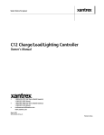
Installation & Service Manual for the X3001 REbus™ Inverter
Revision Table
Revision
1.0
1.1
1.2
1.3
1.4
Date
2012-06-27
2012-09-17
2012-11-10
2014-01-01
2014-10-24
Changes
Initial Release
Changes from UL1741 and CSA review
Changes for Intertek listing report
Updates for Gamma build
REbus wiring conventions & additional troubleshooting steps
1
General Remarks
Congratulations! You have purchased the Pika Energy X3001 REbus™ bidirectional DC/AC inverter, a
dependable, efficient component of your clean energy system. The X3001 is the result of the Pika team’s
careful development and testing, building on decades of experience in the fields of power electronics
and renewable energy systems.
The X3001 is an electrically non-isolated single-stage inverter designed for high-efficiency bidirectional
conversion between a REbus™ Microgrid and 220-240 VAC 60 Hz split-phase utility service. This inverter
is passively cooled for high reliability and low noise. A replaceable capacitor bank ensures that even in
the unusual event of capacitor failure, an easy remedy is available. An illuminated display and intuitive
system of menus enable you to display the energy output of every component of your renewable energy
system, including the energy exported by the inverter to the grid. The inverter also serves as an
information gateway, enabling monitoring and control of your entire renewable energy system.
Unlike conventional inverters, which only connect to one type of energy source, Pika’s X3001 is designed
to operate as the hub for an expandable network of renewable energy devices, based on the REbusTM
renewable energy standard.
What is REbusTM?
The underlying technology behind Pika Energy’s X3001 Inverter is an innovative energy management
technology or ‘smart microgrid’ called REbus™. REbus™ is a DC energy network that operates alongside
the existing AC infrastructure, enabling customers to build cost-effective, scalable renewable energy
systems. The REbusTM network is designed to serve as an open interconnection standard for networking
next-generation energy technology – like Wi-Fi or USB for green energy!
IMPORTANT! Only REbusTM compatible components may be used in connection with this inverter. Do
not connect the output of a PV array or any other non-REbusTM electrical source to the inverter
terminals. Serious property damage and/or personal injury may result.
2
Contents
1 Regarding this Document ......................................................................................................................... 4
1.1 Symbols used in this document .......................................................................................................... 4
1.2 Standards ............................................................................................................................................ 4
1.3 Data Label ........................................................................................................................................... 4
2 Important safety information and instructions ......................................................................................... 5
2.1 Appropriate Usage .............................................................................................................................. 5
2.2 AC Output Details................................................................................................................................ 5
3 Notes concerning installation and operation ............................................................................................ 6
3.1 Intended (normal) use ........................................................................................................................ 6
3.2 Pika Energy Factory Limited Warranty................................................................................................ 6
3.3 Service ................................................................................................................................................. 8
4 The REbusTM Microgrid............................................................................................................................... 9
4.1 Simple and efficient power distribution ............................................................................................. 9
4.2 Integrated Power Line Carrier (PLC) communications ........................................................................ 9
4.3 REbus™ Control Protocol (RCP)........................................................................................................... 9
5 Designing a REbus™ system ..................................................................................................................... 10
6 Installation ............................................................................................................................................... 11
6.1 Checking for shipping damage.......................................................................................................... 11
6.2 Inverter mounting ............................................................................................................................. 11
6.3 Electrical connection notes ............................................................................................................... 15
6.4 AC utility connection ......................................................................................................................... 16
6.5 REbus™ DC connection ..................................................................................................................... 16
6.6 Wiring the inverter............................................................................................................................ 17
6.7 Commissioning the inverter .............................................................................................................. 19
6.8 Operation .......................................................................................................................................... 19
7 Troubleshooting ....................................................................................................................................... 20
3
1 Regarding this Document
This manual contains important instructions for the X3001 Inverter that must be followed during
installation and maintenance of the inverter. The X3001 is designed and tested according to
international safety requirements, but as with all electrical and electronic equipment, certain
precautions must be observed when installing and/or operating the X3001. To reduce the risk of
personal injury and to ensure the safe installation and operation of the X3001, you must carefully read
and follow all instructions, cautions and warnings in this user manual.
Store this manual so that it is always easily accessible.
1.1 Symbols used in this document
WARNING: This indicates a fact or feature very important for the safety of the user to
prevent injury or death and/or which can cause serious hardware damage if not
applied appropriately.
CAUTION: Presents information to prevent damage to this product
EARTH GROUND SYMBOL
1.2 Standards
The Pika X3001 Bidirectional REbus™ Inverter is certified by Intertek to be compliant with the UL
1741/IEEE 1547 standards as they apply to utility-interactive inverters.
1.3 Data Label
A permanently affixed label indicating the device specifications, serial number, and manufacturing date
is located on the bottom surface of the inverter enclosure. Tampering with label can void warranty.
4
2 Important safety information and instructions
IMPORTANT SAFETY INSTRUCTIONS
SAVE THESE INSTRUCTIONS
This manual contains important instructions for model X3001 that shall be followed during installation
and maintenance of the Pika X3001 Inverter.
WARNING: Before installing the Pika Energy X3001 Inverter, read all instructions and caution
markings in this manual and on the X3001 as well as on other REbus™ devices.
WARNING: Electrical installation in the United States shall be done in accordance with all local
electrical codes and/or the National Electrical Code (NEC), ANSI/NFPA 70.
WARNING: Electrical installation in Canada shall be done in accordance with all local electrical
codes and/or the Canadian Electrical Code.
WARNING: Connecting the X3001 to the electric utility grid must only be done after receiving
prior approval from the utility company and installation completed only by qualified personnel/licensed
electrician(s).
2.1 Appropriate Usage
The X3001 is an electrically non-isolated single-stage inverter designed for high-efficiency bidirectional
conversion between a REbus™ microgrid and a 220-240 VAC split-phase utility. Refer to this inverter
installation manual for detailed information about the product and its intended use. The inverter may
only be operated with REbus™ devices. Do not use the inverter for purposes other than those described
here. Alternative uses, modifications to the inverter or the installation of components not expressly
recommended or sold by the manufacturer void the warranty claims and operating permission. Contact
the Pika Energy technical support if you need clarification regarding proper use of the inverter.
2.2 AC Output Details
The X3001 is to be connected to a split-phase 220-240VAC utility only. This means 120VAC from line to
neutral and 240VAC from line to line. The AC neutral is not bonded to ground in the inverter. It is the
responsibility of the installer to bond neutral to ground externally. The input and output circuits are
isolated from the enclosure. System grounding to the ground lugs provided in the wiring box is the
responsibility of the installer.
5
3 Notes concerning installation and operation
3.1 Intended (normal) use
Your inverter is strictly constructed according to approved safety requirements. Improper use may lead
to lethal hazards for operators and/or damage to devices and property. The X3001 is certified to comply
with the UL 1741 standard for utility-interactive devices, and includes important safety features
including ‘anti-islanding’, which shuts down the inverter in the event of a grid power failure to avoid
back-feeding power during a grid outage, which could result in injury to utility repair personnel.
Improper use or modification of the X3001 may result in serious property damage, personal injury or
death.
REBUS™ INPUT ONLY! The X3001 is designed to accept regulated direct current (DC) from REbusTMcompatible devices (e.g. REbusTM-compatible wind turbine, REbusTM-compatible PV Link unit) into gridcompatible alternating current (AC). DO NOT CONNECT PHOTOVOLTAIC MODULES DIRECTLY TO THE
REBUS™ INPUTS OF THE X3001 INVERTER. DOING SO WILL VOID THE WARRANTY AND MAY DAMAGE
THE INVERTER.
The X3001 is typically operated in conjunction with a fixed connection to the utility grid, however it may
be operated in conjunction with an approved standalone inverter as listed in the X3001 AC Coupling
Application Note, available by contacting Pika Technical Service. This unit is provided with fixed trip
limits and shall not be aggregated above 30 kW on a single Point of Common Connection.
Any use other than the specified intended use shall not be deemed intended or normal use, and may
result in property damage, personal injury or death. Pika is not liable for damage or injuries caused by
unintended use.
Damage caused by unintended use is at the sole risk of the operator.
“Intended use” shall also include adherence to the operating and installation instructions.
Your trained and authorized installer must obtain all necessary permits and agreements from your local
government and your utility company for a legal and code-compliant installation of your REbus™ Smart
Microgrid system. See the User Manual for more detail.
3.2 Pika Energy Factory Limited Warranty
Pika Energy LLC (“Pika”) has developed a reliable, efficient inverter, designated X3001 (“Inverter”), that
is designed to withstand normal operating conditions when used in accordance with its intended use
and in compliance with instructions in the accompanying Installation Manual and User Manual shipped
with the unit. The Pika limited warranty (“Limited Warranty”) covers defects in workmanship and
materials of the Pika Inverter (“Defective Product”) for a period of five (5) years from the date of original
purchase of such Inverter at point of sale to the originally-installed end user location (the “Warranty
Period”). During the Warranty Period, the warranty is transferable to a different owner as long as the
Inverter remains installed at the originally-installed end user location.
6
During the Warranty Period, if Pika determines through inspection the existence of a defect that is
covered by the Limited Warranty, Pika will at its option, either (1) repair or replace the Defective
Product free of charge, or (2) provide a credit or refund to the owner of the system at the originally
installed end user location in an amount not to exceed the then-current price of (a) a “like kind” inverter
that is available for purchase by the system owner at the time of the Limited Warranty claim, or (b) the
original cost of the Pika Inverter that is subject to a Limited Warranty claim.
If Pika elects to repair or replace the Defective Product, Pika will, at its option, use new and/or
reconditioned parts in repairing or replacing the Defective Product. Pika reserves the right to use parts
or products of original or improved design in the repair or replacement of Defective Product. If Pika
repairs or replaces a Defective Product, the Limited Warranty continues on the repaired or replacement
product for the remainder of the original Warranty Period or ninety (90) days from the date of Pika’s
return shipment of the repaired or replacement product, whichever is later. The Limited Warranty
covers both parts and labor necessary to repair the Defective Product (if Pika elects to repair the
Defective Product), but does not include labor costs related to (i) un-installing the Defective Product or
(i) if applicable, re-installing a repaired or replacement product. To the extent applicable, the Limited
Warranty also covers the costs of shipping a repaired or replacement product from Pika, via a nonexpedited freight carrier selected by Pika, to locations within the United States (including Alaska and
Hawaii) and Canada, but not to other locations outside the United States or Canada. The Limited
Warranty does not cover, and Pika will not be responsible for, shipping damage or damage caused by
mishandling by the freight carrier and any such damage is the responsibility of the freight carrier.
To obtain repair or replacement service, credit or refund (as applicable) under this Limited Warranty,
the customer must comply with the following policy and procedure:
• Many problems can be addressed in the field. Prior to returning a product, customer must
contact Pika technical support to evaluate and troubleshoot the problem in the original
installation setting.
• All Defective Product must be returned with a Return Merchandise Authorization Number
(RMA) which customer must request from Pika.
• Requests for RMA must include the following information:
o Proof-of-purchase of the Defective Product in the form of (1) the dated purchase
receipt from the original purchase of the product at point of sale to the end user, or (2)
the dated dealer invoice or purchase receipt showing original equipment manufacturer
(OEM) status, or (3) the dated invoice or purchase receipt showing the product
exchanged under warranty
o Model number of the Defective Product
o Serial number of the Defective Product
o Detailed description of the defect.
o Shipping address for return of the repaired or replacement product (as applicable).
• All Defective Product authorized for return must be returned in the original shipping container
or other packaging that is equally protective of the product.
• The returned Defective Product must not have been disassembled or modified without the prior
written authorization of Pika.
Pika Inverters are designed to withstand normal operating conditions and typical wear and tear when
used for their original intent and in compliance with the installation and operating instructions supplied
with the original equipment. The Limited Warranty does not apply to, and Pika will not be responsible
7
for, any defect in or damage to any Pika inverter: (1) that has been misused, neglected, tampered with,
altered, or otherwise damaged, either internally or externally; (2) that has been improperly installed,
operated, handled or used, including use under conditions for which the product was not designed, use
in an unsuitable environment, or use in a manner contrary to the Pika User Manual or applicable laws or
regulations; (3) that has been subjected to fire, water, generalized corrosion, biological infestations, acts
of God, or input voltage that creates operating conditions beyond the maximum or minimum limits
listed in the Pika Inverter specifications, including high input voltage from generators or lightning strikes;
(4) that has been subjected to incidental or consequential damage caused by defects of other
components of the system; or (5) if the original identification markings (including trademark or serial
number) of such Inverter have been defaced, altered, or removed. The Limited Warranty does not cover
costs related to the removal, installation or troubleshooting of the customer’s electrical systems. The
Limited Warranty does not extend beyond the original cost of the Pika Inverter.
THE LIMITED WARRANTY IS THE SOLE AND EXCLUSIVE WARRANTY GIVEN BY PIKA AND, WHERE
PERMITTED BY LAW, IS MADE EXPRESSLY IN LIEU OF ALL OTHER WARRANTIES, EXPRESS OR IMPLIED,
STATUTORY OR OTHERWISE, INCLUDING, WITHOUT LIMITATION, WARRANTIES OF TITLE, QUALITY,
MERCHANTABILITY, FITNESS FOR A PARTICULAR PURPOSE OR NONINFRINGEMENT OR WARRANTIES AS
TO THE ACCURACY, SUFFICIENCY OR SUITABILITY OF ANY TECHNICAL OR OTHER INFORMATION
PROVIDED IN MANUALS OR OTHER DOCUMENTATION. IN NO EVENT WILL PIKA BE LIABLE FOR ANY
SPECIAL, DIRECT, INDIRECT, INCIDENTAL OR CONSEQUENTIAL DAMAGES, LOSSES, COSTS OR EXPENSES
HOWEVER ARISING, WHETHER IN CONTRACT OR TORT, INCLUDING WITHOUT LIMITATION ANY
ECONOMIC LOSSES OF ANY KIND, ANY LOSS OR DAMAGE TO PROPERTY, OR ANY PERSONAL INJURY.
To the extent any implied warranties are required under applicable law to apply to the Pika Inverter,
such implied warranties shall be limited in duration to the Warranty Period, to the extent permitted by
applicable law. Some states and provinces do not allow limitations or exclusions on implied warranties
or on the duration of an implied warranty or on the limitation or exclusion of incidental or consequential
damages, so the above limitation(s) or exclusion(s) may not apply. This Limited Warranty gives the
customer specific legal rights, and the customer may have other rights that may vary from state to state
or province to province.
3.3 Service
WARNING: Do not attempt to repair the X3001 Inverter. The inverter contains no userserviceable parts.
If the Pika X3001 Inverter fails, first contact Pika customer service at (207) 887-9105 for troubleshooting
help. See the Warranty section for details on terms and conditions for repair or replacement under
warranty. You must obtain an RMA (Returned Merchandise Authorization) number prior to returning
the unit. Obtain the assistance of a skilled and qualified installer to safely disconnect the inverter for
shipment.
Technical Support Information:
•
•
•
Support department hours: 9AM to 5PM, Monday – Friday (excluding holidays)
Phone: (207) 887-9105
Email: [email protected]
8
4 The REbusTM Microgrid
The REbusTM Microgrid is the underlying technology that allows for the efficient and robust
interconnection of different types of renewable energy products and loads. This section is informational
only and not required knowledge for operation of your Pika X3001 Inverter.
4.1 Simple and efficient power distribution
The REbusTM Microgrid architecture was designed with renewable energy in mind. A clean-sheet
approach to power distribution resulted in the most practical and efficient interconnection technology
available. The microgrid operates at variable voltage in a defined band, between +/- 180-200 V relative
to ground which simultaneously allows for efficient power transmission, reduced shock hazard, and
simplified electronics for a bidirectional utility grid converter such as the X3001. The variable voltage
communicates energy availability to the attached REbus™ devices, which allows for prioritized energy
storage and load shedding. The microgrid is designed to support many different types of renewable
energy sources and power converters, as well as accommodating future DC loads that are presently in
development.
4.2 Integrated Power Line Carrier (PLC) communications
The REbus™ microgrid standard also specifies an optional power line carrier communication technology
that enables devices on the same microgrid to communicate with one another. The X3001 uses this
capability to gather information about your system such as the status and energy production of your
Pika T701 Wind Turbine or your solar array, which connects to the REbus™ microgrid through the Pika
S2001 PV Link.
4.3 REbus™ Control Protocol (RCP)
REbus™ Control Protocol is a communications protocol developed specifically for the transfer of data
between REbus™-compatible power converters and data management products. RCP is an openstandard protocol which enables independent developers to interface with REbus™ products and create
software and applications to enhance user experience. Please visit the Pika Energy website to learn
more about RCP and the software applications that are currently available.
9
5 Designing a REbus™ system
Your trained and qualified installer will work with the Pika Energy technical support team to design the
right system for your site. Please consult with Pika Energy sales department at (207) 887-9105 or on the
web at http://www.pika-energy.com to find an installer near you.
The Pika Energy product system is designed from the ground up for unmatched flexibility. First and
foremost, the X3001 Inverter accepts input from any combination of REbus™-compatible sources. In
fact, the X3001 Inverter supports up to 32 devices on the REbus™ microgrid network, and the automatic
power management capability of REbus™ allows the total power rating of sources on the network to
exceed the inverter power rating by up to 2X. As of publication, Pika Energy offers the following REbus™
products in addition to the X3001 Inverter:
•
•
•
•
T701 Wind Turbine
S2001 PV Link
B801 Battery Charge Controller
REport Data Monitor
Check the Pika Energy website at http://www.pika-energy.com for the latest selection of REbus™compatible product offerings.
10
6 Installation
6.1 Checking for shipping damage
The X3001 Inverter is thoroughly checked and tested before it is shipped. The inverters can be damaged
in shipping, despite the carefully designed cardboard packaging.
Please inspect the inverter thoroughly after it is delivered. If any damage is seen please immediately
notify the shipping company. If there is any question about potential shipping damage, contact Pika
Energy. Please capture a photograph of the damage if possible.
Do not accept unit if visibly damaged or note visible damage when signing shipping company receipt.
Report damage immediately to the shipping company. Do not remove the unit from its packaging. If it is
determined that the unit must be returned, a RMA# must be obtained from Pika Energy.
6.2 Inverter mounting
The X3001 Inverter is a powder-coated steel enclosure (see Figure 1 for dimensions). The inverter is
shipped complete and does not require a separate mounting bracket. A wall mounting bracket to permit
mounting on a narrow structural member (e.g. stud) may be available, contact Pika Energy for details.
•
•
•
•
•
•
•
For the longest possible life, the X3001 should be mounted out of direct rain, either under a
weather proof overhang or indoors.
The inverter should be restricted from direct sun exposure by mounting on the North side of a
building or structure, indoors, or behind a sun shield. This will best prevent power derating due
to inverter heatsink temperatures above 50 C. The maximum ambient temperature is 60 C. See
Operations manual for additional details.
If feasible, the inverter should be installed away from areas where animals congregate, as the
high frequency (33 kHz) switching of the electronics may disturb them.
During operation, the inverter heatsink may be hot and should be situated in locations where it
will not be subject to incidental contact.
Installation in close proximity to the AC distribution panel may eliminate the need for a
supplemental AC service disconnect. Consult local inspectors or the NEC for details.
The passive cooling system in the Pika X3001 will work best when the inverter is mounted on a
flat, smooth, vertical wall.
Minimum clearances must be maintained, as shown in Figure 2 below.
11
Figure 1 Pika X3001 Dimensions
12
Figure 2 Inverter Minimum Clearance
Mounting surface must be suitable for installing #10 (~M5) pan head screws (suitable for tightening with
screwdriver). These screws can be installed in wood, metal, or masonry. If screw anchors are used (e.g.
concrete expansion anchor), they must be rated to hold the 11 kg (25 lb) inverter with appropriate
safety factor. Drywall is not a recommended mounting surface for the inverter. Mounting surface should
be vertical.
13
Figure 3 Mounting Hole Diagram
Figure 4 Mounting Screw Diagram
Use the included mounting template to accurately mark and drill holes for installing the X3001. Install
two of the included screws into mounting surface 345.8 mm (13.6 in.) apart as shown in Figure 4. Leave
a minimum of a 3 mm gap between the head of the screw and the mounting surface to accept the
enclosure foot. Install inverter over these two screws. Remove M3 screws securing inverter cover and
open cover. Install second two #10 (or equivalent) screws in lower mounting holes. Tighten all screws.
14
6.3 Electrical connection notes
Figure 5 Example X3001 system layout with S2001 PV Link and T701 Wind Turbine
WARNING: All electrical installations in the United States shall be done in accordance with all
local electrical codes and/or the National Electrical Code (NEC), ANSI/NFPA 70.
WARNING: Electrical installation in Canada shall be done in accordance with all local electrical
codes and/or the Canadian Electrical Code.
WARNING: To reduce the risk of fire, always connect the inverter to a dedicated 15A (or 20A) 2pole circuit breaker without multiwire branch circuits.
The X3001 Inverter is equipped with concentric electrical knockouts suitable for ½ or ¾” conduit fittings.
Pika Energy recommends the use of conduit fittings (hubs)which are raintight or wet location hubs that
comply with the requirements in the Standard for Fittings for Conduit and Outlet Boxes, UL 514B. AC &
DC terminals allow for 14 to 8 AWG copper conductors. Earth ground terminals allow for 14 to 8 AWG
copper or aluminum conductors.
15
6.4 AC utility connection
WARNING: The wiring of the inverter’s AC connections must only be done with the AC
distribution panel circuit breaker off.
WARNING: Perform a high potential test on all existing wiring before any connections are made!
Never trust existing wiring until a high potential test has been performed. Pika recommends 1kV testing
on all REbusTM wiring. Failure to high potential test existing wiring before installation will void warranty!
For questions concerning high potential testing contact Pika Technical Support.
The X3001 is a 240V/60Hz AC grid-connected inverter. Specifically, a split-phase connection with a
neutral is required. It cannot be used with a 120 V AC single-phase connection. A dedicated 15 (or 20)
amp 2–pole circuit breaker is required for each inverter. An AC service disconnect may be required by
local codes or the NEC.
Multiple X3001 units can be used at the same location/facility assuming all codes are followed including
NEC, local building codes and area utility guidelines. If multiple units are used, each inverter should have
its own dedicated circuit breaker. Contact Pika about configuring the power line communications in
applications with adjacent inverters.
For 50Hz applications, contact Pika Energy for a X3001/50Hz product.
6.5 REbus™ DC connection
WARNING: The wiring of the inverter’s REbus™ connections must only be done with the AC
distribution panel circuit breaker off and REbus™ sources (e.g. S2001 PV Link, T701 Wind Turbine) either
disabled or generation capability removed. Completely cover the surface of all PV arrays with opaque
(dark) material, remove string fuses, or use other methods to ensure PV cannot output power to the
S2001 PV Link. Lower T701 to ground and secure blades from spinning. Alternatively, disable S2001 PV
Link or T701 Wind Turbine using X3001 Inverter interface. Confirm with a meter that the REbus™
Microgrid is below 50 VDC before performing any wiring operations.
WARNING: Hazardous voltage is still present on the REbus™ inverter after disconnection of all
inputs (AC and DC). Allow 3 minutes for the inverter to discharge the DC voltage completely.
WARNING: Perform a high potential test on all existing wiring before any connections are made!
Never trust existing wiring until a high potential test has been performed. Pika recommends 1kV testing
on all REbusTM wiring. Failure to high potential test existing wiring before installation will void warranty!
For questions concerning high potential testing contact Pika Technical Support.
16
Figure 5 Wiring Diagram
6.6 Wiring the inverter
1. Open inverter cover by hinging up, position the kickstand on the right side to catch and support
the lid.
2. Remove electrical conduit knockouts, either ½” or ¾”, on the side or bottom surface of inverter.
Install electrical conduit.
3. The AC distribution panel circuit breaker should be off and REbus™ sources (e.g. S2001 PV Link,
T701 Wind Turbine) either disabled or generation capability removed before any wiring is
connected. Completely cover the surface of all PV arrays with opaque (dark) material, remove
string fuses, or use other methods to ensure PV cannot output power to the S2001 PV Link.
17
Lower the T701 to ground and secure blades from spinning. Confirm with a voltmeter that the
REbus™ is below 50 VDC before performing any wiring operations.
4. Run wires from AC distribution panel to inverter, connect to terminals (reference Figure 5 for
wiring locations), torque to 2.1 Nm (18.5 in-lb)
WARNING:
5.
REbus
TM
Before wiring the DC (REbus™) side of the inverter, ensure all
wiring in follows the wiring convention described below:
RE+ : Red wire (alternatively, white wire marked with at least three continuous
wraps of red electrical tape at all terminations, as shown below)
RE-
: Blue wire (alternatively, black wire marked with at least three continuous
wraps of blue electrical tape at all terminations, as shown below)
Ground: Green wire (alternatively, bare wire)
6. Run wires from REbus™ DC sources to inverter, connect to terminals (reference Figure 5 for
wiring locations), torque to 2.1 Nm (18.5 in-lb). See Figure 6 REbus™ Wiring Color Code for
wiring reference.
Figure 6 REbus™ Wiring Color Code
18
7. Connect earth ground wires, torque to as follows:
Wire Size
8 AWG
10-14 AWG
Screw Torque
4.5 Nm (40 in-lb)
4.0 Nm (35 in-lb)
WARNING: Make a final check for correctness of all AC and DC wiring to the inverter and in the
system. In particular, check that the polarity of the DC wiring is correct throughout the entire system.
Reverse polarity will damage system components, may create a fire hazard and will void inverter
warranty!
8. Close inverter cover and install two cover screws.
6.7 Commissioning the inverter
Once the inverter is mounted, and both AC and REbus™ microgrid connections have been made, ensure
the inverter enclosure lid is securely attached with its mounting screws. Ensure no wiring is accessible by
personnel (install covers on junction boxes, attach shroud on turbine, etc). The inverter is now ready to
power ON in accordance with the following steps:
1. Turn on the system DC disconnect (if the system is equipped with optional DC disconnect)
2. Turn on the dedicated 2-pole circuit 240/208VAC circuit breaker on the home/building electrical
panel
3. Turn on the system AC disconnect (if the system is equipped with additional AC disconnect)
4. Turn on the power switch on the bottom surface of the inverter.
5. Watch the LCD for initialization sequence.
6. Use the arrow keys to scroll to the inverter page. Enable the inverter by pressing the center
button, selecting “Enable” and press “Confirm”. If this is the first time powering up the inverter,
devices connected on REbusTM will be automatically discovered.
7. See the X3001 Operation Manual for enabling REbusTM devices, connecting to Wi-Fi and other
system configuration.
6.8 Operation
Please consult the Pika X3001 User Manual for instruction and important safety precautions related to
the operation of your new inverter. Inverter operation is best performed by persons who have read and
understand the user manual.
19
7 Troubleshooting
The following table offers a few initial actions to try in the event that the inverter is not functioning as
expected. Contact technical service if the symptoms persist.
WARNING: Disconnect all AC power and disable sources of DC power before troubleshooting
any wiring. Always check wiring with a voltmeter to ensure safe working conditions! Do not open the lid
of the inverter without turning off all sources of power connected to it.
Symptom
Unit does not power up
Ground Fault
Unit displays waiting state
LCD Screen displays solid black or solid
white
Inverter display does not show connected
REbus™ devices OR connected devices
have status “offline” although the
inverter is operating.
Inverter shows devices that are no longer
connected to REbusTM
Action
1) Check that AC power in the range of 110-130 VAC is
present between each of the AC line terminals and
ground
2) Toggle the power switch on the bottom side of the
inverter
1) Turn off the AC breaker that feeds the inverter.
Verify no voltage is present on AC or DC wiring and
disconnect the REbus™ (DC) side wiring and ensure
it is not touching anything. Power ON the inverter
and make sure the ground fault message is no
longer displayed.
2) Check the wiring on the REbus™ (DC) side. Ensure
that none of the DC wires are touching the
enclosure or earth ground wires. RE+ and REshould measure >1MΩ to ground with a
multimeter. Some possible scenarios: incorrect
REbus™ wiring, lightning arrestor failed, chaffed
wire insulation, or broken wire.
1) Some fault conditions warrant a 5 minute timeout,
if the unit does not return to normal operation after
5 minutes contact technical service.
1) Turn the unit off using the power switch on the
bottom, wait 1 minute and turn it back on again.
1) Check that ground wire on REbus™ side is
connected to the lug in the wiring compartment.
There must be a continuous ground wire from the
X3001 to the device for communications to work
properly.
2) Reseat the cable that attaches the LCD screen to
the main board within the X3001. Note this is a
polarized connector. It may be dislodged during
shipping or installation.
3) Call technical support for further troubleshooting.
1) Delete unwanted devices by selecting “Remove”
under the device page. Reference X3001 Operations
Manual for further detail.
20
21