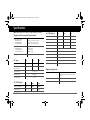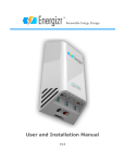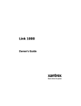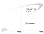
1
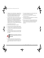
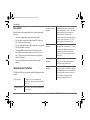
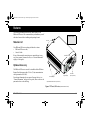
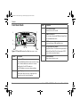
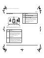
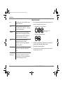
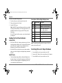
PROWatt SW Inverter NA.book Page 1 Wednesday, August 5, 2009 2:24 PM
TM
TM
FA
PO
T
UL
W ER
RE
MO
TE
PROwatt SW 600 shown.
Owner’s Guide
Sine Wave Inverter
PROwatt SW 600
PROwatt SW 1000
PROwatt SW 2000
PROWatt SW Inverter NA.book Page 2 Wednesday, August 5, 2009 2:24 PM
PROWatt SW Inverter NA.book Page i Wednesday, August 5, 2009 2:24 PM
About Xantrex
Date and Revision
Xantrex Technology Inc. (www.xantrex.com), a subsidiary of Schneider Electric, is a
world leader in the development, manufacturing and marketing of advanced power
electronic products and systems for the renewable and mobile power markets. The
company's products convert and control raw electrical power from any central,
distributed, renewable, or backup power source into high-quality power required by
electronic equipment and the electricity grid. Xantrex is headquartered in Vancouver,
Canada, with facilities in the United States, Germany, Spain, and a joint venture in
China.
August 2009 Rev B
Trademarks
Document Part Number
975-0529-01-01
Product Numbers
PROwatt SW 600: 806-1206
PROwatt SW 1000: 806-1210
PROwatt SW 2000: 806-1220
Xantrex, PROwatt, and Smart choice for power are trademarks of Schneider
Electric, registered in the U.S. and other countries. Other trademarks, registered
trademarks, and product names are the property of their respective owners and are
used herein for identification purposes only.
Contact Information
Telephone:
1 800 670 0707 (toll free North America)
1 408 987 6030 (direct)
Notice of Copyright
Fax:
1 800 994 7828 (toll free North America)
Xantrex PROwatt™ SW Sine Wave Inverter Owner’s Guide © August 2009 Xantrex
Technology Inc. All rights reserved. No part of this document may be reproduced in
any form or disclosed to third parties without the express written consent of: Xantrex
Technology Inc., 161-G South Vasco Road, Livermore, California, USA 94551.
Xantrex Technology Inc. reserves the right to revise this document and to
periodically make changes to the content hereof without obligation or organization of
such revisions or changes unless required to do so by prior arrangement.
Email:
[email protected]
Web:
www.xantrex.com
Exclusion for Documentation
UNLESS SPECIFICALLY AGREED TO IN WRITING, XANTREX TECHNOLOGY INC. (“XANTREX”)
(A) MAKES NO WARRANTY AS TO THE ACCURACY, SUFFICIENCY OR SUITABILITY OF ANY
TECHNICAL OR OTHER INFORMATION PROVIDED IN ITS MANUALS OR OTHER DOCUMENTATION;
(B) ASSUMES NO RESPONSIBILITY OR LIABILITY FOR LOSSES, DAMAGES, COSTS OR EXPENSES,
WHETHER SPECIAL, DIRECT, INDIRECT, CONSEQUENTIAL OR INCIDENTAL, WHICH MIGHT ARISE
OUT OF THE USE OF SUCH INFORMATION. THE USE OF ANY SUCH INFORMATION WILL BE ENTIRELY
AT THE USER ’S RISK; AND
(C) REMINDS YOU THAT IF THIS MANUAL IS IN ANY LANGUAGE OTHER THAN ENGLISH,
ALTHOUGH STEPS HAVE BEEN TAKEN TO MAINTAIN THE ACCURACY OF THE TRANSLATION, THE
ACCURACY CANNOT BE GUARANTEED. APPROVED XANTREX CONTENT IS CONTAINED WITH THE
ENGLISH LANGUAGE VERSION WHICH IS POSTED AT WWW.XANTREX.COM.
975-0529-01-01
i
PROWatt SW Inverter NA.book Page ii Wednesday, August 5, 2009 2:24 PM
About This Guide
Purpose
The purpose of this Owner’s Guide is to provide explanations and
procedures for operating, installing, maintaining, and troubleshooting the
PROwatt™ SW Sine Wave Inverter.
Scope
The Guide provides safety guidelines, as well as information about
operating, installing, and troubleshooting the inverter. It does not provide
details about particular brands of batteries. You need to consult individual
battery manufacturers for this information.
Xantrex recommends that installation should be handled by qualified
installers including licensed technicians and electricians. Qualified
installers have knowledge and experience in installing electrical equipment,
knowledge of the applicable installation codes, and awareness of the
hazards involved in performing electrical work and how to reduce those
hazards.
Audience
CAUTION
Cautions identify conditions or practices that could result in
damage to the unit or other equipment.
Important: These notes describe things which are important for you to
know, however, they are not as serious as a caution or warning.
Related Information
You can find more information about Xantrex Technology Inc. as well as
its products and services at www.xantrex.com.
The product marking on the left (yellow background, black
exclamation point) when found imprinted on electrical and
electronic units and appliances means that you are to refer to
this guide for cautions and warnings.
The Guide is intended for users and operators of the PROwatt™ SW Sine
Wave Inverter.
Conventions Used
The following conventions are used in this guide.
WARNING
Warnings identify conditions that could result in personal injury
or loss of life.
ii
Xantrex PROwatt™ SW Sine Wave Inverter Owner’s Guide
PROWatt SW Inverter NA.book Page iii Wednesday, August 5, 2009 2:24 PM
Important Safety Instructions
3.
IMPORTANT: READ AND SAVE THIS OWNER’S GUIDE FOR FUTURE
REFERENCE.
This chapter contains important safety instructions for the PROwatt™ SW
Sine Wave Inverter.
Before using the PROwatt™ SW Sine Wave Inverter, READ ALL
instructions and cautionary markings on or provided with the PROwatt™
SW Sine Wave Inverter, the batteries, and all appropriate sections of this
guide.
4.
5.
WARNING: Shock, fire, and heat hazard. Risk of
injury to persons.
Do not operate the PROwatt™ SW Sine Wave Inverter if it has
received a sharp blow, been dropped, or otherwise damaged in any
way. If the PROwatt™ SW Sine Wave Inverter is damaged, see the
Warranty section.
Do not disassemble the PROwatt™ SW Sine Wave Inverter. It
contains no user-serviceable parts. See Warranty for instructions on
obtaining service. Attempting to service the PROwatt™ SW Sine
Wave Inverter yourself may result in a risk of electrical shock or fire.
Internal capacitors remain charged after all power is disconnected.
To reduce the risk of electrical shock, disconnect DC power from the
PROwatt™ SW Sine Wave Inverter before attempting any
maintenance or cleaning or working on any circuits connected to the
PROwatt™ SW Sine Wave Inverter. Turning off controls will not
reduce this risk.
Precautions When Working With Batteries
1.
2.
Do not expose the PROwatt™ SW Sine Wave Inverter to rain, snow,
spray, or bilge water. To reduce risk of fire hazard, do not cover or
obstruct the ventilation openings. Overheating may result.
To avoid a risk of fire and electric shock, make sure that wiring is in
good condition, adequately rated, and not undersized. Do not operate
the PROwatt™ SW Sine Wave Inverter with damaged or substandard
wiring.
975-0529-01-01
WARNING: Explosion or fire hazard.
1.
Follow all instructions published by the battery manufacturer and the
manufacturer of the equipment in which the battery is installed to
reduce the risk of battery explosion.
iii
PROWatt SW Inverter NA.book Page iv Wednesday, August 5, 2009 2:24 PM
2.
3.
4.
5.
6.
7.
Working in the vicinity of lead-acid batteries is dangerous. Batteries
generate explosive gases during normal operation. Therefore, you
must read this guide and follow the instructions exactly before
installing or using your PROwatt™ SW Sine Wave Inverter.
This equipment contains components which tend to produce arcs or
sparks. To prevent fire or explosion, do not operate the PROwatt™
SW Sine Wave Inverter in compartments containing batteries or
flammable materials, or in locations that require ignition-protected
equipment. This includes any space containing gasoline-powered
machinery, fuel tanks, as well as joints, fittings, or other connections
between components of the fuel system.
Make sure the area around the battery is well ventilated.
Never smoke or allow a spark or flame near the engine or batteries.
Use caution to reduce the risk or dropping a metal tool on the battery.
It could spark or short circuit the battery or other electrical parts and
could cause an explosion.
If you need to remove a battery, always remove the ground terminal
from the battery first. Make sure all accessories are off so you don’t
cause a spark.
9.
Have someone within range of your voice or close enough to come to
your aid when you work near a lead-acid battery.
10. Have plenty of fresh water and soap nearby in case battery acid
contacts skin, clothing, or eyes.
11. Wear complete eye protection and clothing protection. Avoid touching
your eyes while working near batteries.
12. If battery acid contacts skin or clothing, wash immediately with soap
and water. If acid enters your eye, immediately flood it with running
cold water for at least twenty minutes and get medical attention
immediately.
WARNING: Risk of personal injury due to burns
or battery acid.
8.
iv
Remove all metal items, like rings, bracelets, and watches when
working with lead-acid batteries. Lead-acid batteries produce a short
circuit current high enough to weld metal to skin, causing a severe
burn.
Xantrex PROwatt™ SW Sine Wave Inverter Owner’s Guide
PROWatt SW Inverter NA.book Page v Wednesday, August 5, 2009 2:24 PM
FCC Statement
WARNING
This device complies with Part 15 of the FCC rules. Operation
is subject to the following two conditions:
(1) This device may not cause harmful interference and
(2) this device must accept any interference received, including
interference that might cause undesired operation.
NOTE: This equipment has been tested and found to comply
with the limits for a Class A digital device, pursuant to part 15
of the FCC Rules. These limits are designed to provide
reasonable protection against harmful interference when the
equipment is operated in a commercial environment. This
equipment generates, uses, and can radiate radio frequency
energy and, if not installed and used in accordance with the
instruction manual, may cause harmful interference to radio
communications. Operation of this equipment in a residential
area is likely to cause harmful interference in which case the
user will be required to correct the interference at his own
expense.
975-0529-01-01
v
PROWatt SW Inverter NA.book Page vi Wednesday, August 5, 2009 2:24 PM
PROWatt SW Inverter NA.book Page vii Wednesday, August 5, 2009 2:24 PM
Contents
Important Safety Instructions . . . . . . . . . . . . . . . . . . . . . . . . . . . . . . . . . . . . . . . . . . . . . . . . . . . . . . . . . . . . . . . . . . . . . . . . . . . .iii
Introduction . . . . . . . . . . . . . . . . . . . . . . . . . . . . . . . . . . . . . . . . . . . . . . . . . . . . . . . . . . . . . . . . . . . . . . . . . . . . . . . . . . . . . . . . . 1
Features . . . . . . . . . . . . . . . . . . . . . . . . . . . . . . . . . . . . . . . . . . . . . . . . . . . . . . . . . . . . . . . . . . . . . . . . . . . . . . . . . . . . . . . . . . . . 3
Installation . . . . . . . . . . . . . . . . . . . . . . . . . . . . . . . . . . . . . . . . . . . . . . . . . . . . . . . . . . . . . . . . . . . . . . . . . . . . . . . . . . . . . . . . . . 6
Operation . . . . . . . . . . . . . . . . . . . . . . . . . . . . . . . . . . . . . . . . . . . . . . . . . . . . . . . . . . . . . . . . . . . . . . . . . . . . . . . . . . . . . . . . . . 15
Troubleshooting . . . . . . . . . . . . . . . . . . . . . . . . . . . . . . . . . . . . . . . . . . . . . . . . . . . . . . . . . . . . . . . . . . . . . . . . . . . . . . . . . . . . . 19
Specifications . . . . . . . . . . . . . . . . . . . . . . . . . . . . . . . . . . . . . . . . . . . . . . . . . . . . . . . . . . . . . . . . . . . . . . . . . . . . . . . . . . . . . . . 21
Warranty and Return Information . . . . . . . . . . . . . . . . . . . . . . . . . . . . . . . . . . . . . . . . . . . . . . . . . . . . . . . . . . . . . . . . . . . . . . . 22
PROWatt SW Inverter NA.book Page viii Wednesday, August 5, 2009 2:24 PM
PROWatt SW Inverter NA.book Page 1 Wednesday, August 5, 2009 2:24 PM
Introduction
Thank you for purchasing the PROwatt™ SW Sine Wave Inverter.
The PROwatt SW Inverter is a high quality, true sine wave output
inverter. It is designed to operate AC loads as if these loads were
operating from grid/utility supplied power in household AC outlets.
To get the most out of your PROwatt™ SW Sine Wave Inverter,
carefully read and follow the instructions in this guide.
PROwatt SW Inverter Series
There are three PROwatt SW Inverter models in the series namely:
• PROwatt SW 600,
• PROwatt SW 1000, and
• PROwatt SW 2000.
Quality Power
The PROwatt SW Inverter is a professional-quality, mid-range
inverter designed to handle a variety of applications including
compact microwaves, TVs, VCRs, coffee makers, and small power
tools.
• The PROwatt SW Inverter provides optimal continuous power,
making it ideal for large single loads, intermittent loads, or
multiple smaller loads.
• The inverter’s high surge capability lets you handle many hardto-start loads, including large TVs, refrigerators, and freezers.
This Guide contains information about all three models. Unless
specified by the model name, all features, functions, and instructions will pertain to all models. All the models of the inverter will be
referred to collectively as PROwatt SW Inverter.
•
975-0529-01-01
Model
Continuous
Surge Power
PROwatt SW 600
540 watts
1200 watts
PROwatt SW 1000
900 watts
2000 watts
PROwatt SW 2000
1800 watts
3000 watts
The unit’s low standby battery demand means you don’t have
to worry about excessive drain on your battery if you leave the
inverter on for a few days. When the inverter is on but no power
is being supplied to a load, the inverter draws less than 800 mA
from the battery.
1
PROWatt SW Inverter NA.book Page 2 Wednesday, August 5, 2009 2:24 PM
Introduction
Ease of Use
Superior features and rugged durability have been combined with
ease of use:
• The unit is compact, light weight, and easy to install.
• You can power loads directly from the dual GFCI-protected
AC receptacles on the front panel.
• Easy-to-read digital display on the front panel lets you monitor
system performance at a glance.
• The optional PROwatt Remote Panel lets you control the
inverter from a convenient location—up to 25 feet (7.6 m)
away—while the inverter itself is mounted out of sight and
close to the batteries.
• A convenient USB port powers most modern electronic
products.
Comprehensive Protection
The PROwatt SW Inverter is equipped with the following protection
features:
GFCI protection
De-energizes the AC circuits and thereby
protects the user from electric shock if a ground
fault occurs.
Low battery voltage
alarm
Alerts you if the battery has become discharged
to 11 V or lower.
2
Low battery voltage
shutdown
Automatically shuts the inverter down if the
battery voltage drops below 10.5 V. This feature
protects the battery from being completely
discharged. Within five minutes after
shutdown, the unit recovers automatically once
the battery voltage reaches above 11.5 Vdc.
After five minutes, the unit turns itself off.
High battery voltage
shutdown
Shuts the inverter down automatically if the
input voltage rises to more than 15.5 V. Within
five minutes after shutdown, the unit recovers
automatically once the battery voltage falls
below 15.5 Vdc. After five minutes, the unit
turns itself off.
AC output overload
shutdown
Shuts the unit down automatically if a short
circuit occurs or if the loads attached to the
inverter exceed the operating limits.
Over temperature
shutdown
Turns the inverter off if its temperature rises
above an acceptable level. Within five minutes
after shutdown, the unit recovers automatically
once the temperature of the unit cools down.
After five minutes of operating in high
temperature, the unit turns itself off.
Xantrex PROwatt™ SW Sine Wave Inverter Owner’s Guide
PROWatt SW Inverter NA.book Page 3 Wednesday, August 5, 2009 2:24 PM
Features
The following information describes the main features of the
PROwatt SW Inverter. We recommend that you familiarize yourself
with these features before installing and operating the unit.
Owner’s Guide
DC Input
Materials List
Your PROwatt SW Inverter package includes these items:
• PROwatt SW Inverter unit,
• Owner’s Guide.
If any of these materials are missing or are unsatisfactory in any
way, please contact Customer Service (see “Contact Information”
on page i of this guide).
ventilation openings
Optional Accessory
The PROwatt SW Inverter can also be installed with the PROwatt
Remote Panel that comes with a 25-foot (7.6 m) communications
cable (part number 808-9001).
For ordering information, please contact Customer Service (see
“Contact Information” on page i of this guide). Please reference the
part number above when ordering.
LT
FAU
WER
PO
OTE
REM
Digital Display
AC Outlets
(GFCI-protected)
Mounting flanges
Optional PROwatt Remote Panel (not shown)
Figure 1 PROwatt SW Inverter (PROwatt SW 600 shown)
975-0529-01-01
3
PROWatt SW Inverter NA.book Page 4 Wednesday, August 5, 2009 2:24 PM
Features
Front Panel Details
1
7
POWER
Description
3
Power Switch Button
Turns the inverter ON or OFF.
4
Remote Switch Port
Use to connect the optional PROwatt Remote Panel
via a communications cable.
5
USB Port
Powers and charges USB-enabled devices.
6
GFCI-protected AC Outlets
Equipped with two AC outlets that are protected by a
standard Ground Fault Circuit Interruptor (GFCI)
device with reset and test buttons.
7
Ventilation Holes
Allows internal heat to escape.
FAULT
2
3
Feature
6
REMOTE
4
5
Figure 2 PROwatt SW Inverter Front Panel (PROwatt SW 600 shown)
Feature
Description
1
Indicator LEDs
Green LED indicates that the unit is on and receiving
power. When a shutdown occurs due to an error
condition the Green LED remains on.
Red LED indicates an error or alarm condition.
2
Digital Display
Shows input voltage (in volts), output power (in
kilowatts), and error code information.
4
Xantrex PROwatt™ SW Sine Wave Inverter Owner’s Guide
PROWatt SW Inverter NA.book Page 5 Wednesday, August 5, 2009 2:24 PM
Features
Serial No.
Back Panel Details
4
Feature
Description
3
Chassis Ground (GND) Terminal
4
Negative (–) DC Terminal
Accepts lug or ring connectors appropriate to the
cable size being used. See Table 1 : Voltage Drop
Per Foot of DC Cable on page 10 for
recommendations.
1
2
3
Figure 3 PROwatt SW Inverter Back Panel (PROwatt SW 600 shown)
Feature
Description
1
Positive (+) DC Terminal
Accepts lug or ring connectors appropriate to the
cable size being used. See Table 1 : Voltage Drop
Per Foot of DC Cable on page 10 for
recommendations.
2
Cooling Fan
Automatically turns on when internal temperature
reaches more than 122 °F (50 °C). It turns off when
the internal temperature falls below 122 °F (50 °C).
975-0529-01-01
5
PROWatt SW Inverter NA.book Page 6 Wednesday, August 5, 2009 2:24 PM
Installation
Guidelines
Tools and Materials
Follow all instructions from this guide and instructions including
safety guidelines from the battery manufacturer. Installing battery
cables require some electrical knowledge and local electrical codes.
•
•
WARNING
If you do not have some electrical knowledge and
knowledge of local electrical codes or are not comfortable
installing cables yourself, use a qualified installer
including a licensed technician and electrician. Qualified
installers have knowledge and experience in installing
electrical equipment, knowledge of the applicable
installation codes, and awareness of the hazards involved
in performing electrical work and how to reduce those
hazards.
6
•
•
•
•
Adjustable wrench for fastening DC terminal bolts,
Two battery cables (copper, appropriately sized according to
application) with connectors already crimped by the company
or store where you purchased the cables,
Ground cable (copper, appropriately sized) for attaching to the
ground chassis,
DC-rated fuses (and fuse holders),
Screwdriver (flathead and Philips), power screwdriver, or
power drill for use in mounting the inverter,
Mounting screws (4) size #10.
Basic Installation Steps
1.
Determine battery capacity.
2.
Determine a charging system.
3.
Choose a location.
4.
Mount the inverter.
5.
Connect the chassis ground.
6.
Connect the battery cables.
Xantrex PROwatt™ SW Sine Wave Inverter Owner’s Guide
PROWatt SW Inverter NA.book Page 7 Wednesday, August 5, 2009 2:24 PM
Installation
Determine Battery Capacity
Battery type and battery size strongly affect the performance of the
PROwatt SW Inverter. Therefore, you need to identify the type of
loads your inverter will be powering and how much you will be
using them between charges. Once you know how much power you
will be using, you can determine how much battery capacity you
need. Xantrex recommends that you purchase as much battery
capacity as possible.
Choose A Location
CAUTION: Risk of inverter damage.
The PROwatt SW Inverter contains components that tend
to produce arcs or sparks. To prevent fire or explosion, do
not install the inverter in compartments containing
batteries or flammable materials or in locations that
require ignition-protected equipment.
CAUTION: Risk of inverter damage.
WARNING: Risk of electrical shock.
The PROwatt SW Inverter must only be connected to a
battery that has a nominal output of 12 volts. The PROwatt
SW Inverter will:
• Not operate if connected to a 6 volt battery and
• Be damaged if connected to a 24 volt battery.
Do not install the PROwatt SW Inverter in a wet
environment or in any other environment where moisture
can occur and enter the inverter enclosure through the
ventilation openings. This unit is not intended for marine
applications.
Determine A Charging System
The charging system must be appropriate for your particular
installation. A well-designed charging system will ensure that
power is available when you need it and that your batteries remain
in top condition. Inadequate charging will degrade system
performance and the wrong type of charger will reduce battery life.
For a list of Xantrex Battery Chargers, go to www.xantrex.com or
contact Customer Service (see “Contact Information” on page i of
this guide).
975-0529-01-01
WARNING
To reduce the risk of fire, do not cover or obstruct the
ventilation openings. Do not install the PROwatt SW
Inverter in a zero-clearance compartment. Overheating
may result.
7
PROWatt SW Inverter NA.book Page 8 Wednesday, August 5, 2009 2:24 PM
Installation
Mount The Inverter
Dry
Do not allow water or other liquids to drop or
splash on the inverter.
Cool
Ambient air temperature should be between
32 ºF and 104 º F (0 ºC and 40 º C)—the cooler
the better within this range.
Ventilated
Allow at least 2 inches (5 cm) of clearance
around the inverter for air flow. Ensure that
ventilation openings on the DC end and the
bottom of the unit are not obstructed.
1.
Select an appropriate mounting location and orientation. The
unit can be oriented in any way, such as:
•
Horizontally on a vertical surface or
DC connections should NOT
point up or down.
•
On or under a horizontal surface.
POWER
FAULT
REMOTE
REMOTE
FAULT
Do not install the inverter in the same
compartment as batteries or in any
compartment capable of storing flammable
liquids like gasoline.
Close to battery Do not use excessive DC cable lengths: they
increase wire resistance and reduce input
power.
Protected from
battery gases
8
POWER
Safe
2.
Hold the inverter against the mounting surface and mark the
positions using the mounting flanges as guide.
3.
Pilot-drill the four mounting holes.
4.
Fasten the inverter to the mounting surface using corrosionresistant hardware sized #10.
Do not mount the inverter where it will be
exposed to gases produced by the batteries.
These gases are very corrosive and prolonged
exposure will damage the inverter.
Xantrex PROwatt™ SW Sine Wave Inverter Owner’s Guide
PROWatt SW Inverter NA.book Page 9 Wednesday, August 5, 2009 2:24 PM
Installation
Connect the Chassis Ground
WARNING: Risk of electrical shock.
Never operate the PROwatt SW Inverter without
connecting it to the ground. Electrical shock hazard could
result.
The PROwatt SW Inverter has a screw terminal labeled CHASSIS
GND on the outside of the rear panel as shown in Figure 3,
“PROwatt SW Inverter Back Panel (PROwatt SW 600 shown)” on
page 5.
Follow the guidelines below to connect the inverter’s chassis to the
ground.
Grounding Locations
The chassis ground terminal must be connected to a grounding
point. The grounding point varies depending on where you install
the PROwatt SW Inverter. Follow the guidelines that correspond to
your type of installation.
Recreational
Vehicle
975-0529-01-01
Connect the CHASSIS GND screw to the
vehicle’s chassis using a minimum 8 AWG
copper wirea (preferably with green/yellow
insulation).
Fixed Location
Connect the CHASSIS GND screw to your
system’s DC grounding point using a minimum
6 AWG wirea. The system’s grounding point is
usually the AC service entrance grounding
point or a separate ground rod. For a solar PV
(photovoltaic) installation, this is usually the
same rod used to ground the PV array.
a.Xantrex recommends that the grounding conductor (grounding wire) should be the same wire
size as the DC cables.
Connect The Battery Cables
Important: Use of a qualified installer strongly recommended.
To operate safely and effectively, the PROwatt SW Inverter needs
proper DC cables and DC-rated fuse(s). Because the PROwatt SW
Inverter has low-voltage and high-current input, low-resistance
wiring between the battery and the inverter is essential to deliver the
maximum amount of usable energy to your load.
9
PROWatt SW Inverter NA.book Page 10 Wednesday, August 5, 2009 2:24 PM
Installation
Cabling Guidelines
Follow these guidelines and refer to Table 1 : Voltage Drop Per
Foot of DC Cable on page 10 to determine battery cable lengths.
• Use 4 AWG copper (90 ºC insulation rating) as the smallest
battery cable size. This will minimize the voltage drop between
the battery and the inverter. If the cables cause an excessive
voltage drop, the inverter may shut down when drawing higher
currents because the voltage at the inverter input drops below
10.5 volts.
• Keep all cables as short as possible, and ensure that each cable
between the inverter and the battery is no longer than 6 feet
(1.8 m).
• Have all wires and cables terminated with correct and
appropriately-sized connectors and have the connectors
crimped at the place of purchase.
• Do not use aluminum. It has about 1/3 more resistance than
copper cable of the same size, and it is difficult to make good,
low-resistance connections to aluminum wire.
Table 1 : Voltage Drop Per Foot of DC Cable
Inverter
Output (W)
600
1000
1500
3000
Current (A)
60
100
150
300
Wire
Size
(AWG)
Resistance
(ohms/ft)
@ 25 °C
4
0.000253
0.0152
0.0253
0.0380
0.0759
3
0.000201
0.0121
0.0201
0.0302
0.0603
2
0.000159
0.0096
0.0159
0.0239
0.0477
1
0.000126
0.0076
0.0126
0.0189
0.0378
0
0.000100
0.0060
0.0100
0.0150
0.0300
2/0
0.000079
0.0048
0.0079
0.0119
0.0237
3/0
0.000063
0.0038
0.0063
0.0095
0.0189
4/0
0.000050
0.0030
0.0050
0.0075
0.0150
Voltage Drop per Foot
Note: Xantrex recommends a size 0 cable with a maximum cable
length of 6 feet (1.8 m).
For example:
Note: Voltage Drop per foot = Current value × Resistance value
So for a 600 W inverter output with a DC cable of size 0, multiply
the maximum current of 60 A with 0.000100. The result is 0.00600
voltage drop per feet. If the cable is 6 feet long, the total voltage
drop is 0.00600 × 6 ( × 2) = 0.072. (Cable length multiplied by 2.)
So for a battery operating at 12.6 V at battery terminal the voltage at
the inverter terminal drops to 12.53 V.
10
Xantrex PROwatt™ SW Sine Wave Inverter Owner’s Guide
PROWatt SW Inverter NA.book Page 11 Wednesday, August 5, 2009 2:24 PM
Fuse/Circuit Breaker Sizing Guidelines
Because batteries can produce thousands of amps, you are required
to install DC-rated fuses (or circuit breakers) that can safely
withstand the short-circuit current batteries can produce.
To select the correct fuse type and size:
1.
Determine the total cold cranking amp rating for your
battery(s).
Note: The cold cranking amp rating of each battery is displayed
on the battery case. If it is not, contact the battery manufacturer
to find out.
For example:
• If you are using one battery to power your inverter and its
rating is 500, the total cold cranking amp rating is 500.
• If you are powering your inverter with two batteries in
parallel, and each has a rating of 500, the total cold
cranking amp rating is 1000.
2.
Installation
Note: The AIC is the amount of battery short-circuit amperage
that the fuse can safely withstand.
• If the Total Cold Cranking Amps indicate that the AIC is
2,700 amps or less, see Table 3 for the correct ANL fuse.
• If the Total Cold Cranking Amps indicate that the AIC is
up to 200,000 amps or if you require a “code fuse”, see
Table 3 for the correct Class T fuse.
Table 2 Cold Cranking Amps / AIC
Total Cold Cranking
Amps
Ampere Interrupting Capacity
(AIC)
650 or less
1500
651–1100
3000
over 1100
5000
Table 3 Fuse Ratings
Model
ANL Fuse
Class T
PROwatt SW 600
80 A
80 A
PROwatt SW 1000
150 A
150 A
PROwatt SW 2000
250 A
250 A
Once you have determined the total cold cranking amp rating of
your batteries, identify the corresponding Ampere Interrupting
Capacity (AIC) of the fuse or breaker required for your system
by referring to Table 2.
975-0529-01-01
11
PROWatt SW Inverter NA.book Page 12 Wednesday, August 5, 2009 2:24 PM
Installation
Cabling Procedure
TO VEHICLE
Consult the following configurations and determine a match
specific to your installation and follow the installation procedure
“To connect the battery cables:” that comes next.
FROM ALTERNATOR
OR CHARGER
VEHICLE
STARTING
BATTERY
ISOLATOR
GROUND TO
VEHICLE
CHASSIS
FROM ALTERNATOR
OR CHARGER
FUSE OR
CIRCUIT
BREAKER
ISOLATOR
BATTERY
SELECTOR
SWITCH
GROUND TO
VEHICLE
CHASSIS
TO OTHER
DC LOADS
FUSE OR
CIRCUIT
BREAKER
ALL
1
OFF
2
FUSE OR
CIRCUIT
BREAKER
DEEP-CYCLE
BATTERY
DEEP-CYCLE
BATTERY
GROUND TO
VEHICLE
CHASSIS
TO OTHER
DC LOADS
DEEP-CYCLE
AUXILIARY
BATTERY
DEEP-CYCLE
BATTERY
VEHICLE
STARTING
BATTERY
FUSE OR
CIRCUIT
BREAKER
GROUND TO
VEHICLE
CHASSIS
TO VEHICLE
FUSE OR
CIRCUIT
BREAKER
DEEP-CYCLE
BATTERY
BATTERY
SELECTOR
SWITCH
FUSE OR
CIRCUIT
BREAKER
ALL
1
OFF
2
GROUND TO
VEHICLE
CHASSIS
GROUND TO
VEHICLE
CHASSIS
Figure 5 Configuration for Heavy Loads
Figure 4 Configuration for Normal Loads
12
To connect the battery cables:
1.
Make sure the inverter is off and assemble the terminated
cables (cables with connectors) that you bought.
2.
Line up the connectors that will join the cables to the battery,
battery selector switch, and fuse (or circuit breaker).
Xantrex PROwatt™ SW Sine Wave Inverter Owner’s Guide
PROWatt SW Inverter NA.book Page 13 Wednesday, August 5, 2009 2:24 PM
Installation
WARNING: Risk of electrical shock or fire.
CAUTION: Risk of inverter damage due to
reverse polarity.
The PROwatt SW Inverter does not come with a DC-rated
fuse (or circuit breaker) to safely withstand the shortcircuit current batteries can produce. To avoid the risk of
electrical shock or fire, install a DC-rated fuse (and fuse
holder) on the positive battery terminal.
3.
Install a DC-rated fuse on the positive battery terminal.
Alternatively, install a DC-rated circuit breaker that connects to
the positive battery terminal.
The fuse (or circuit breaker must have an Ampere Interrupting
Capacity (AIC) that exceeds the short-circuit current available
from the battery. For guidance, see “Cold Cranking Amps /
AIC” on page 11.
4.
When configuring for heavy loads (see Figure 5), install a
battery selector switch and connect it to the DC-rated fuse (or
circuit breaker).
5.
On the inverter side, attach the connectors of the positive and
negative cables into the cabling terminals of the inverter.
Note: Make a secure connection. Loose connectors cause
excessive voltage drop and may cause overheated wires and
melted insulation.
Note: The red terminal is positive (+) and the black terminal is
negative (–). Power connections to the PROwatt SW Inverter
must be positive to positive and negative to negative.
975-0529-01-01
A reverse polarity connection (positive to negative) will
blow a fuse in the inverter and may permanently damage
the unit. Damage caused by a reverse polarity connection
is not covered by your warranty.
6.
Attach the connector on the positive cable to the DC-rated fuse
(or circuit breaker) which is connected to the positive terminal
of the battery.
When configuring for heavy loads (see Figure 5), attach the
connector on the positive cable to the battery selector switch
that is already connected to the DC-rated fuse (or circuit
breaker).
Note: Make a secure connection. Loose connectors cause
excessive voltage drop and may cause overheated wires and
melted insulation.
WARNING: Risk of explosion or fire.
Do not complete the next step if flammable fumes are
present. Explosion or fire may result. Thoroughly ventilate
the battery compartment before making this connection.
13
PROWatt SW Inverter NA.book Page 14 Wednesday, August 5, 2009 2:24 PM
Installation
7.
Attach the connector on the negative cable to the negative
battery terminal.
Note: This is the last cable connection. You may observe a
spark when making this last connection.
Note: Make a secure connection. Loose connectors cause
excessive voltage drop and may cause overheated wires and
melted insulation.
8.
If you have installed a battery selector switch, use it to select
one of the batteries or battery banks.
9.
Turn on the inverter.
10. Check the front panel of the inverter. The digital display should
show 12–13 volts, depending on the voltage of the battery. If it
does not, check your battery and the connection to the inverter.
The other indicators should be off.
14
Xantrex PROwatt™ SW Sine Wave Inverter Owner’s Guide
PROWatt SW Inverter NA.book Page 15 Wednesday, August 5, 2009 2:24 PM
Operation
Turning the Inverter On and Off
Turning the Inverter Off Between Charges
The power switch on the inverter’s front panel turns the control
circuit in the PROwatt SW Inverter on and off.
To toggle the inverter on and off from its front panel:
When the power switch is on but no power is being supplied to a
load, the inverter draws less than 800 mA from the battery. This is a
low current draw. It would take a week to discharge a 150 Ah
battery at this current, so you don’t have to worry about excessive
drain on your battery if you leave the inverter switched on for a few
days.
If you are not planning to recharge your battery within a week or so,
switch the inverter off.
1.
Press the inverter’s power switch button (for half a second) to
turn On the inverter (from Off).
2.
Press the inverter’s power switch button (for one second) to
turn Off the inverter (from On).
Note: When the inverter’s power switch button is Off, the
inverter draws no current from the battery.
WARNING: Risk of electrical shock.
The unit’s power switch when turned off does not
disconnect power from the PROwatt SW Inverter.
Operating Several Loads at Once
If you are going to operate several loads from the PROwatt SW
Inverter, turn them on separately after you have turned the inverter
on.
This will ensure that the inverter does not have to deliver the
starting current for all the loads at once.
975-0529-01-01
GFCI-Protected AC Outlets
The AC outlets are Ground Fault Circuit Interrupter (GFCI) outlets.
This protects you against hazardous electrical shocks that could be
caused by dampness, faulty mechanism in the appliance, worn
insulation, etc. GFCI-protected outlets cut off hazardous electrical
shocks quickly enough so an adult in normal health is not seriously
injured (infants and small children may still be affected).
Important: Test the GFCI periodically to make sure it is operating
correctly.
15
PROWatt SW Inverter NA.book Page 16 Wednesday, August 5, 2009 2:24 PM
Operation
To test (or reset) the GFCI protection:
1.
Press the unit’s power switch to turn the inverter On.
2.
Plug a test lamp into the AC outlet.
3.
Push the TEST button.
Note: The RESET button should pop out and the power should
turn Off (the lamp should go out). If the lamp remains lit, or if
the RESET button does not pop out, the GFCI may not be
functioning.
If the GFCI trips by itself at any time, reset it and perform the
preceding test.
Reading the Front Panel Indicators
Description of LED and Digital Display Codes
LED
Digital Display
Description
Green
1.3.5.
Example: 13.5 volts
Green
0.2.5.
Example: 0.25 Kw (250 watts)
Red
E.0.1.
Under voltage alarm and/or
Under voltage shutdown
Red
E.0.2.
Over voltage shutdown
Red
E.0.3.
Over load shutdown
Red
E.0.4.
Over temperature shutdown
Red
E.1.0.
Short circuit or output circuit
overheat
Indicator LEDs
•
•
If the Green LED is On, it indicates that the unit is On. Under
normal operating conditions, the AC outlets and USB port have
power. However, even under an error condition such as a
shutdown, the Green LED may still remain On.
If the Red LED is on, it indicates an error or alarm condition
and an error code is displayed on the digital display underneath
the LED.
Digital Display
•
•
16
Under normal operating conditions, the digital display shows
the input voltage (in volts) and the output power (in kilowatts).
Under error or alarm conditions, the digital display shows an
error code and the Red LED turns on.
Note: The audio alarm will sound for five minutes. After five
minutes, the unit will turn off.
Restarting After an AC Output Shutdown
1.
Press and hold the unit’s power switch to turn it Off.
2.
Remove all AC loads or let the unit cool down for 15 minutes.
3.
Press and hold the unit’s power switch to turn it On.
Xantrex PROwatt™ SW Sine Wave Inverter Owner’s Guide
PROWatt SW Inverter NA.book Page 17 Wednesday, August 5, 2009 2:24 PM
Operation
Operating Limits
Power Output
The PROwatt SW Inverter will deliver the following power
continuously, depending on input voltage and ambient temperature.
The inverter will deliver more than 10% of its continuous power
rating for approximately five minutes. The inverter must cool down
for 15 minutes before it can resume operation above its continuous
power rating.
Model
Powera
Output Input
Currentb Voltage
PROwatt SW 600
540 W
4.5 A
PROwatt SW 1000
900 W
7.5 A
PROwatt SW 2000
1800 W
15 A
13 Vdc
Tempera
ture
Input Voltage
The input voltage limits are shown in the following table.
Voltage Range
Comment
Normal
10.5–15.5 V
n/a
975-0529-01-01
13–14.5 V
n/a
Low Voltage Alarm
Voltage is
11.0 V or less
The audible low battery
alarm sounds.
Operating
Condition
Voltage Range
Comment
Low Voltage
Shutdown
Voltage is
10.5 V or less.
The unit shuts down to
protect the battery from
being over-discharged.
High Voltage
Shutdown
Voltage is
The unit shuts down to
15.5 V or more. protect itself from
excessive input voltage.
Note: Although the
PROwatt SW Inverter
incorporates overvoltage protection, it can
still be damaged if input
voltage exceeds 16 V.
Unit restarts after
low voltage
shutdown
11.5 V
Ambient
25 °C
(77 °F)
a.Applies to resistive loads such as incandescent lights.
b.Applies to reactive loads such as motors.
Operating
Condition
Peak Performance
The unit will not restart
unless the battery
voltage is acceptable for
running the load.
17
PROWatt SW Inverter NA.book Page 18 Wednesday, August 5, 2009 2:24 PM
Operation
The PROwatt SW Inverter will operate many AC loads within its
power rating. However, some appliances and equipment may be
difficult to operate. Please see “Exceptional Loads” below carefully.
diameter of the battery cables are appropriate. Check that the battery
connections are good and that the battery is fully charged. If the
cables are sized correctly, the connections are good, and the battery
is charged, but the voltage still drops below 11 volts, you may need
to use a larger battery.
USB Loads
Battery Charging Frequency
A lot of USB-powered devices such as portable music (MP3)
players, mobile phones, and video game players can be charged and
powered safely via the standard USB port. However, some devices
such as portable GPS receivers and certain cameras may not work
and even cause damage even if you use the USB cable that came
with the product. Be sure that the device only accepts 5 volts and
can be charged or powered using other sources of power. See the
device’s owner’s guide under specifications for information.
When possible, recharge your batteries when they are about 50%
discharged or earlier. This gives them a much longer life cycle than
recharging when they are almost completely discharged. For
information about battery chargers, see our web site at
www.xantrex.com.
Inverter Loads
Exceptional Loads
Some induction motors used in freezers, pumps, and other motoroperated equipment need high surge currents to start. The PROwatt
SW Inverter may not be able to start some of these motors even
though their rated current draw is within the inverter’s limits.
If a motor refuses to start, observe the VOLTS indicator while you
are trying to start the motor. If the indicator drops below 11 volts
while the PROwatt SW Inverter is trying to start the motor, this may
explain why the motor won’t start. Make sure the length and
18
Maintenance
Routine maintenance is required to keep your PROwatt SW Inverter
operating properly. Periodically you should:
• Clean the exterior of the unit with a damp cloth to prevent the
accumulation of dust and dirt.
• Tighten the screws on the DC input terminals.
Xantrex PROwatt™ SW Sine Wave Inverter Owner’s Guide
PROWatt SW Inverter NA.book Page 19 Wednesday, August 5, 2009 2:24 PM
Troubleshooting
WARNING: Electrical shock and burn hazard.
Do not dismantle the PROwatt SW Inverter. It does not
contain any user-serviceable parts. Attempting to service
the unit yourself could result in an electrical shock or burn.
Troubleshooting Reference
Condition
Possible Cause
Solution
E.0.1.
Under Voltage (low
input) shutdown
Recharge the battery.
Check cables and
connection if secure.
E.0.1.
with persistent low
battery alarm.
Poor DC wiring
and/or poor battery
condition
Use proper cable and
make secure
connections.
Charge the battery or
install a new battery.
E.0.2.
Over Voltage (high
input) shutdown
Make sure the
inverter is connected
to a 12 V battery.
975-0529-01-01
Condition
Possible Cause
Solution
E.0.3.
Overload shutdown
Reduce the load
within the inverter’s
continuous power
rating.
E.0.4.
Heavy load is
connected then AC
output becomes
unavailable.
Over temperature
shutdown
Allow the inverter to
cool off and reduce
the load if
continuous operation
is required.
E.0.4.
Normal load is
connected then AC
output becomes
unavailable.
Over temperature
shutdown
Improve ventilation
and make sure the
inverter’s ventilation
openings are not
obstructed.
Reduce the ambient
temperature, if
possible.
19
PROWatt SW Inverter NA.book Page 20 Wednesday, August 5, 2009 2:24 PM
Troubleshooting
Condition
Possible Cause
Solution
Condition
Possible Cause
Solution
E.1.0.
No output voltage.
Short circuit
Check the AC
wiring for a short
circuit.
No output voltage;
no voltage
indication.
Very heavy load
Remove the load.
The unit is off.
No power to the
inverter.
Inverter fuse open.
Reverse DC polarity.
Output circuit
overheat
Turn the unit off.
Let the unit cool
down, check the fan
for any obstructions
and clear it, or
reduce the load.
Turn the unit back
on.
Turn the inverter on.
Check wiring to the
inverter.
Have a qualified
service technician
check and replace
the fuse if necessary.
Have a qualified
service technician
check and replace
the fuse, making
sure to observe
correct polarity.
The unit is on and
running but there is
no AC output.
The GFCI device
tripped.
Reset the GFCI. See
page 16 for
instructions.
20
Xantrex PROwatt™ SW Sine Wave Inverter Owner’s Guide
PROWatt SW Inverter NA.book Page 21 Wednesday, August 5, 2009 2:24 PM
Specifications
Note: Specifications are subject to change without prior notice.
Physical and Environmental Specifications
AC / USB Output
600
1000
Surge power
1200 W
2000 W
3000 W
Output current (continuous)
4.6 A
7.5 A
15 A
Output current (max)
5.8 A
9.6 A
19.2 A
No load current draw
< 600 mA
< 600 mA
< 800 mA
Length × Width × Height
•
PROwatt SW 600
•
PROwatt SW 1000
•
PROwatt SW 2000
12.2×8.7×3.5 inch. (31×22×8.9 cm)
14×9×3.5 inch. (35×22×8.5 cm)
13.8×11.8×3.9 inch. (35×30×10 cm)
Weight
•
PROwatt SW 600
•
PROwatt SW 1000
•
PROwatt SW 2000
6.5 lbs. (3.0 kg)
7.2 lbs. (3.3 kg)
10.6 lbs. (4.8 kg)
Output voltage (nominal)
Operating temperature
32–104 °F (0–40 °C)
Output waveform
True sine wave
Output frequency
60 Hz ±0.5Hz
DC Input
600
Output voltage range
1000
2000
Efficiency
USB Output
Input power (max at full load)
720 VA
1200 VA
2400 VA
Input current
(max at full load)
60 A
93 A
200 A
120 Vac RMS ±5%
104–127 Vac
Approximately 85–90%
5 Vdc, 500 mA
Regulatory Approvals
Input voltage range
10.5–15.5 Vdc
Low battery alarm
Audible, 11 V
Low battery cutout
10.5 V
AC / USB Output
600
1000
2000
Peak power (5 minutes)
600 W
1000 W
2000 W
Continuous power
540 W
900 W
1800 W
975-0529-01-01
2000
UL 458 5th edition
Power Converters/Inverters and Power Converter/
Inverter Systems for Land Vehicles and Marine
Crafts
CSA 107.1-01
General Use Power Supplies
FCC Part 15, Class A
Electromagnetic Compatibility (EMC)
21
PROWatt SW Inverter NA.book Page 22 Wednesday, August 5, 2009 2:24 PM
Warranty and Return Information
Warranty
What does this warranty cover and how long does it last? This
Limited Warranty is provided by Xantrex Technology Inc.
("Xantrex") and covers defects in workmanship and materials in
your PROwatt™ SW Sine Wave Inverter. This warranty period
lasts for 24 Months from the date of purchase at the point of sale to
you, the original end user customer, unless otherwise agreed in
writing (the “Warranty Period”). You will be required to
demonstrate proof of purchase to make warranty claims.
This Limited Warranty is transferable to subsequent owners but
only for the unexpired portion of the Warranty Period. Subsequent
owners also require original proof of purchase as described in
"What proof of purchase is required?"
What will Xantrex do? During the Warranty Period Xantrex will,
at its option, repair the product (if economically feasible) or replace
the defective product free of charge, provided that you notify
Xantrex of the product defect within the Warranty Period, and
provided that Xantrex through inspection establishes the existence
of such a defect and that it is covered by this Limited Warranty.
Xantrex will, at its option, use new and/or reconditioned parts in
performing warranty repair and building replacement products.
Xantrex reserves the right to use parts or products of original or
improved design in the repair or replacement. If Xantrex repairs or
replaces a product, its warranty continues for the remaining portion
of the original Warranty Period or 90 days from the date of the
22
return shipment to the customer, whichever is greater. All replaced
products and all parts removed from repaired products become the
property of Xantrex.
Xantrex covers both parts and labor necessary to repair the product,
and return shipment to the customer via a Xantrex-selected nonexpedited surface freight within the contiguous United States and
Canada. Alaska, Hawaii and outside of the United States and
Canada are excluded. Contact Xantrex Customer Service for details
on freight policy for return shipments from excluded areas.
How do you get service? If your product requires troubleshooting
or warranty service, contact your merchant. If you are unable to
contact your merchant, or the merchant is unable to provide service,
contact Xantrex directly at:
Telephone: 1 800 670 0707 (toll free North America)
1 408 987 6030 (direct)
Fax:
1 800 994 7828 (toll free North America)
Email:
[email protected]
Website:
www.xantrex.com
Direct returns may be performed according to the Xantrex Return
Material Authorization Policy described in your product manual.
For some products, Xantrex maintains a network of regional
Authorized Service Centers. Call Xantrex or check our website to
see if your product can be repaired at one of these facilities.
Xantrex PROwatt™ SW Sine Wave Inverter Owner’s Guide
PROWatt SW Inverter NA.book Page 23 Wednesday, August 5, 2009 2:24 PM
What proof of purchase is required? In any warranty claim,
dated proof of purchase must accompany the product and the
product must not have been disassembled or modified without prior
written authorization by Xantrex.
Proof of purchase may be in any one of the following forms:
• The dated purchase receipt from the original purchase of the
product at point of sale to the end user; or
• The dated dealer invoice or purchase receipt showing
original equipment manufacturer (OEM) status; or
• The dated invoice or purchase receipt showing the product
exchanged under warranty.
What does this warranty not cover? Claims are limited to repair
and replacement, or if in Xantrex's discretion that is not possible,
reimbursement up to the purchase price paid for the product.
Xantrex will be liable to you only for direct damages suffered by
you and only up to a maximum amount equal to the purchase price
of the product.
This Limited Warranty does not warrant uninterrupted or error-free
operation of the product or cover normal wear and tear of the
product or costs related to the removal, installation, or
troubleshooting of the customer's electrical systems. This warranty
does not apply to and Xantrex will not be responsible for any defect
in or damage to:
a) the product if it has been misused, neglected, improperly
installed, physically damaged or altered, either internally or
externally, or damaged from improper use or use in an
unsuitable environment;
b) the product if it has been subjected to fire, water, generalized
corrosion, biological infestations, or input voltage that creates
975-0529-01-01
Warranty and Return Information
operating conditions beyond the maximum or minimum limits
listed in the Xantrex product specifications including but not
limited to high input voltage from generators and lightning
strikes;
c) the product if repairs have been done to it other than by Xantrex
or its authorized service centers (hereafter "ASCs");
d) the product if it is used as a component part of a product
expressly warranted by another manufacturer;
e) component parts or monitoring systems supplied by you or
purchased by Xantrex at your direction for incorporation into
the product;
f) the product if its original identification (trade-mark, serial
number) markings have been defaced, altered, or removed;
g) the product if it is located outside of the country where it was
purchased; and
h) any consequential losses that are attributable to the product
losing power whether by product malfunction, installation error
or misuse.
23
PROWatt SW Inverter NA.book Page 24 Wednesday, August 5, 2009 2:24 PM
Warranty and Return Information
Disclaimer
Exclusions
Product
If this product is a consumer product, federal law does not allow an
exclusion of implied warranties. To the extent you are entitled to
implied warranties under federal law, to the extent permitted by
applicable law they are limited to the duration of this Limited
Warranty. Some states, provinces and jurisdictions do not allow
limitations or exclusions on implied warranties or on the duration of
an implied warranty or on the limitation or exclusion of incidental
or consequential damages, so the above limitation(s) or exclusion(s)
may not apply to you. This Limited Warranty gives you specific
legal rights. You may have other rights which may vary from state
to state, province to province or jurisdiction to jurisdiction.
THIS LIMITED WARRANTY IS THE SOLE AND EXCLUSIVE WARRANTY
PROVIDED BY XANTREX IN CONNECTION WITH YOUR XANTREX
PRODUCT AND IS, WHERE PERMITTED BY LAW, IN LIEU OF ALL OTHER
WARRANTIES, CONDITIONS, GUARANTEES, REPRESENTATIONS,
OBLIGATIONS AND LIABILITIES, EXPRESS OR IMPLIED, STATUTORY OR
OTHERWISE IN CONNECTION WITH THE PRODUCT, HOWEVER ARISING
(WHETHER BY CONTRACT, TORT, NEGLIGENCE, PRINCIPLES OF
MANUFACTURER'S LIABILITY, OPERATION OF LAW, CONDUCT,
STATEMENT OR OTHERWISE), INCLUDING WITHOUT RESTRICTION ANY
IMPLIED WARRANTY OR CONDITION OF QUALITY, MERCHANTABILITY
OR FITNESS FOR A PARTICULAR PURPOSE. ANY IMPLIED WARRANTY
OF MERCHANTABILITY OR FITNESS FOR A PARTICULAR PURPOSE TO
THE EXTENT REQUIRED UNDER APPLICABLE LAW TO APPLY TO THE
PRODUCT SHALL BE LIMITED IN DURATION TO THE PERIOD
STIPULATED UNDER THIS LIMITED WARRANTY.
IN NO EVENT WILL XANTREX BE LIABLE FOR: (a) ANY SPECIAL,
INDIRECT, INCIDENTAL OR CONSEQUENTIAL DAMAGES, INCLUDING
LOST PROFITS, LOST REVENUES, FAILURE TO REALIZE EXPECTED
SAVINGS, OR OTHER COMMERCIAL OR ECONOMIC LOSSES OF ANY
KIND, EVEN IF XANTREX HAS BEEN ADVISED, OR HAD REASON TO
KNOW, OF THE POSSIBILITY OF SUCH DAMAGE; (b) ANY LIABILITY
ARISING IN TORT, WHETHER OR NOT ARISING OUT OF XANTREX'S
NEGLIGENCE, AND ALL LOSSES OR DAMAGES TO ANY PROPERTY OR
FOR ANY PERSONAL INJURY OR ECONOMIC LOSS OR DAMAGE CAUSED
BY THE CONNECTION OF A PRODUCT TO ANY OTHER DEVICE OR
SYSTEM; AND (c) ANY DAMAGE OR INJURY ARISING FROM OR AS A
RESULT OF MISUSE OR ABUSE, OR THE INCORRECT INSTALLATION,
INTEGRATION OR OPERATION OF THE PRODUCT BY PERSONS NOT
AUTHORIZED BY XANTREX.
24
Xantrex PROwatt™ SW Sine Wave Inverter Owner’s Guide
PROWatt SW Inverter NA.book Page 25 Wednesday, August 5, 2009 2:24 PM
Warranty and Return Information
Return Material Authorization Policy
Return Procedure
For those products that are not being repaired in the field and are
being returned to Xantrex, before returning a product directly to
Xantrex you must obtain a Return Material Authorization (RMA)
number and the correct factory "Ship To" address. Products must
also be shipped prepaid. Product shipments will be refused and
returned at your expense if they are unauthorized, returned without
an RMA number clearly marked on the outside of the shipping box,
if they are shipped collect, or if they are shipped to the wrong
location.
When you contact Xantrex to obtain service, please have your
instruction manual ready for reference and be prepared to supply:
• The serial number of your product
• Information about the installation and use of the unit
• Information about the failure and/or reason for the return
• A copy of your dated proof of purchase
Record these details on page 26.
Package the unit safely, preferably using the original box and
packing materials. Please ensure that your product is shipped fully
insured in the original packaging or equivalent. This warranty will
not apply where the product is damaged due to improper packaging.
Include the following:
• The RMA number supplied by Xantrex Technology Inc.
clearly marked on the outside of the box.
• A return address where the unit can be shipped. Post office
boxes are not acceptable.
• A contact telephone number where you can be reached
during work hours.
• A brief description of the problem.
Ship the unit prepaid to the address provided by your Xantrex
customer service representative.
If you are returning a product from outside of the USA or
Canada In addition to the above, you MUST include return freight
funds and are fully responsible for all documents, duties, tariffs, and
deposits.
If you are returning a product to a Xantrex Authorized Service
Center (ASC) A Xantrex return material authorization (RMA)
number is not required. However, you must contact the ASC prior to
returning the product or presenting the unit to verify any return
procedures that may apply to that particular facility and that the
ASC repairs this particular Xantrex product.
975-0529-01-01
25
PROWatt SW Inverter NA.book Page 26 Wednesday, August 5, 2009 2:24 PM
Warranty and Return Information
Information About Your System
As soon as you open your PROwatt™ SW Sine Wave Inverter
package, record the following information and be sure to keep your
proof of purchase.
❐ Serial Number
❐ Product Number/s
______________________
806-1206
806-1210
806-1220
❐ Purchased From
______________________
❐ Purchase Date
______________________
If you need to contact Customer Service, please record the
following details before calling. This information will help our
representatives give you better service.
❐ Type of installation (e.g.
❐ Battery type (e.g. flooded,
______________________
sealed gel cell, AGM)
❐ DC wiring size and length
______________________
❐ Alarm sounding?
______________________
❐ Description of indicators
______________________
on front panel
❐ Appliances operating
______________________
when problem occurred
❐ Description of problem
______________________
________________________________________________
________________________________________________
______________________
RV, truck)
❐ Length of time inverter
______________________
has been installed
❐ Battery/battery bank size
26
______________________
Xantrex PROwatt™ SW Sine Wave Inverter Owner’s Guide
PROWatt SW Inverter NA.book Page i Wednesday, August 5, 2009 2:24 PM
PROWatt SW Inverter NA.book Page ii Wednesday, August 5, 2009 2:24 PM
Xantrex Technology Inc.
1 800 670 0707 Tel toll free NA
1 408 987 6030 Tel direct
1 800 994 7828 Fax toll free NA
[email protected]
www.xantrex.com
975-0529-01-01
Printed in China