1
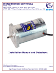
RHINO MOTION CONTROLS
RMCS-1110 v1.0
Hybrid AC Driver with ENABLE
(Max. 80Vdc and 7A per phase)
Installation Manual and Datasheet
http://www.rhinomc.com
Page 1
Hybrid AC Driver [RMCS-1110]
RHINO MOTION CONTROLS
RMCS-1110 v1.0
Hybrid AC Driver with ENABLE
(Max. 80Vdc and 7A per phase)
Key Features
•
•
•
•
•
•
•
•
•
•
Smooth and quiet operation at all speeds and extremely low motor heating
Industrial grade performance for an alternating current servo motor
Field oriented control based low voltage servo loop
Fully configurable position and velocity loop
Input supply voltage from 18VDc to 80VDC
Delivers up to 7amps of continuous current
Selectable gear-ratio for encoder with counts from 4000 to 10000 per revolution
PULSE, DIRECTION and ENABLE inputs with opto-isolated interface
Short-circuit protection for the motor outputs, over-voltage and under-voltage protection
LED indication for power and error states
Description
Thank you for purchasing RMCS-1110, Hybrid AC Driver. RMCS-1110 is Rhino Motion Controls
introductory hybrid low voltage AC drive designed for smooth and quiet operation without compromising
on torque and control at higher speeds. It has short-circuit protection for the motor outputs, over-voltage
and under-voltage protection and will survive accidental motor disconnects while powered-up.
The RMCS-1110 delivers a low-voltage servo performance using a field oriented control (FOC) current
loop for two-phase hybrid PMSM motors. It also provides a fully configurable position and velocity loop
with feed-forward variables to achieve close to zero lag in servo performance.
Two phase PMSM servo systems give an advantage of higher speed, faster response and very low motor
heating.
The RMCS-1110’s FOC control gains are calibrated on start-up based on motor characteristics and also
adjusted dynamically while the motor is in motion. This control algorithm makes it capable of achieving
better torque at higher speeds in comparison to comparable drives in its range.
The PULSE/STEP, DIRECTION and ENABLE inputs are optically isolated. Both inputs work with 2.5V, 3.3V
or 5V logic drive signals. The input drive current is 5mA at 2.5V so almost all logic family (74LS, 74HC,
etc.) can be used to drive these inputs.
The RMCS-1110 hybrid AC drive is warranted to be free of manufacturing defects for six months from the
date of purchase. Please see the section on service, support and warranty at the end of this document.
http://www.rhinomc.com
Page 2
Hybrid AC Driver [RMCS-1110]
RHINO MOTION CONTROLS
RMCS-1110 v1.0
Hybrid AC Driver with ENABLE
(Max. 80Vdc and 7A per phase)
Technical Specifications
Specification
Supply Voltage
Phase Current
Servo Loop Speed
Power Dissipation
Short-Circuit Current
PUL and DIR Voltage
Ambient Temp.
Humidity
Step Frequency
Direction Setup time
Min
18
0.5
500
0
7
2.5
0
0
—
500
Max
80
7
1000
15
10
7
70
95%
200
—
Units
Volts DC
Amps
Hz
Watts
Amps
Volts DC
Celsius
Comments
Between +Ve and GND
As demanded by load
—
In case of motor terminal short
Between + and – input pins
Non condensing
kHz
ns
Steps is clocked on positive edge
Mechanical Specifications
Specification
Dimensions (L * W * H)
Weight
Heat Sink
Mounting Screw Holes
Details
110mm * 77mm *33mm
155gms
Anodized Aluminum 3mm thickness
3.6mm minimum diameter
Caution
•
•
•
•
•
•
•
•
•
•
Read this document carefully before installing and using you drive
Inputs voltage to the drive must not exceed the maximum of 80VDC or it may damage the drive
Reversing polarity power supplied to the drive will damage the drive or power supply
Connecting the power supply wires to the terminals outputs of the motor coils will damage the
drive
Short-circuiting the motor terminals to +Ve power or to each other or to GND may damage the
drive
Excess humidity or condensation on the drive may damage the drive
Voltage in excess of 7V between the PULSE+ and PULSE- or DIR+ and DIR- or ENA+ and ENAinput terminals may damage the opto-isolators
Reverse voltage in excess of 7V between the PULSE- and PULSE+ or DIR- and DIR+ or ENA+ and
ENA- input terminals may damage the opto-isolators
Heat sink is designed to dissipate heat from the drive circuitry as long as the ambient temperature
is less that 70 degrees Celsius. Ambient temperature in excess of that may damage the drive
Do not un-plug the terminals of the motor while the drive is powered up and running
http://www.rhinomc.com
Page 3
Hybrid AC Driver [RMCS-1110]
RHINO MOTION CONTROLS
RMCS-1110 v1.0
Hybrid AC Driver with ENABLE
(Max. 80Vdc and 7A per phase)
Power and Motor Terminal Assignments
Terminal No.
Terminal 1
Terminal 2
Terminal 3
Terminal 4
Terminal 5
Terminal 6
Terminal Name
AA+
BB+
+V
GND
Description
Motor Coil Phase AMotor Coil Phase A+
Motor Coil Phase BMotor Coil Phase B+
Power +Ve (18VDC to 80VDC Max wrt. GND)
Power Ground or Power –Ve
Encoder Terminal Assignments
Terminal No.
Terminal 1
Terminal 2
Terminal 3
Terminal 4
Terminal 5
Terminal 6
Terminal Name
GND
+V
AA+
BB+
Wire Colour
BLACK
RED
GREEN
YELLOW
WHITE
BLUE
Description
Power Ground or Power –Ve
Power +Ve (5VDC wrt. GND)
Motor Coil Phase AMotor Coil Phase A+
Motor Coil Phase BMotor Coil Phase B+
Pulse and Direction Input Assignments
Terminal No.
Terminal 1
Terminal 2
Terminal 3
Terminal 4
Terminal 5
Terminal 6
Terminal Name
ENAENA+
DIRDIR+
PULPUL+
Description
Enable (Motor Free) -Ve optically isolated input
Enable (Motor Free) +Ve optically isolated input
Direction -Ve optically isolated input
Direction +Ve optically isolated input
Pulse -Ve optically isolated input
Pulse +Ve optically isolated input
Switch Selection Table for Step Selection
Resolution
1/10
1/5
1/2
1x
SW1
ON
OFF
ON
OFF
SW2
ON
ON
OFF
OFF
Switch (4): Sets Direction
SW4 ON – Forward Direction
SW4 OFF – Reverse Direction
http://www.rhinomc.com
Page 4
Hybrid AC Driver [RMCS-1110]
RHINO MOTION CONTROLS
RMCS-1110 v1.0
Hybrid AC Driver with ENABLE
(Max. 80Vdc and 7A per phase)
RS-232 command port
A 4pin command port is available on the drive for debug and tuning routines. This port is assessable on
the main drive board after opening the drive cover. The communication setting are given below along with
a command list. A cable for connecting a RS-232 DB9 to the port is usually shipped with the drive.
After connecting it to a computer the drive can be accessed by simple commands using any terminal
software. The baud rate of 115200bps is default with no flow control, 8 bit data and 1 stop bit.
The below list of commands can be used to read or write a register. A new line and carriage return is
required to process any command.
Command and Register Table
Command List
A
B
C
D
E
F
G
H
I
J
K
L
N
O
R
Register Description
Default
Max
Position Proportional Gain
Velocity Proportional Gain
Velocity Integral Gain
Velocity Damping
No. of Poles in Motor Construction
Encoder Counts Per Revolution
Current Loop P-Gain
Current Limit
Position Error Limit
Current Loop I-Gain
Acceleration Feed-Forward
Home Position in Counts
Velocity Feed-Forward
Position Integral Gain
LED Trigger Level for Current
256
4000
25
100
50
4000
96
2400
8
48
7
0
65
48
1200
30000
30000
30000
30000
100
10000
1000
4000
200
1000
100
0
30000
1000
4000
Description
Default
Max
Go To Absolute Position
Go To Relative Position
Start Data Stream
Stop Data Stream
Go to Acceleration and Deceleration
Go to Velocity Setting
0
0
0
0
1
0
+/-32767
+/-32767
Additional Commands
Command List
P
M
S
T
a
s
1000
2000
http://www.rhinomc.com
Page 5
Hybrid AC Driver [RMCS-1110]
RHINO MOTION CONTROLS
RMCS-1110 v1.0
Hybrid AC Driver with ENABLE
(Max. 80Vdc and 7A per phase)
X
Y
Set Defaults
Save to EEPROM
Power Supply Selection
The general rule of thumb to get the most out of the motor is to drive it with a supply voltage that is atleast 3 to 4 times its rated supply voltage. A DC regulated power supply with good low-ESR decoupling
capacitors on its output is recommended for best performance of this drive.
LED Status and Error Codes
There is a single LED on this drive for power and error status messages. In case the LED is blinking or
flickering please check all connections and powered-down, wait for 5 seconds and then power-up the drive
once again.
LED State
Green LED ON and steady
Red LED Flickering randomly
Red LED blinking
Message
Powered up and calibrated
Current Trigger Level Achieved
Short circuit on motor terminals or drive message to connection error
Guide to General Problems
Problem Symptom
Motor is not rotating
Motor rotates in the wrong direction
LED is blinking
Drive is not powering up (no LED)
Erratic Motion on Motor
Possible Reasons and Solutions
Drive is not powered up
Motor is not connected properly to the drive
Drive is in an error state, check LED status
Pulse and Direction inputs are not connected properly or are not supplying
enough current
Motor Phase connections may be reversed
Check LED status messages in this document and check connections and voltages
accordingly
Drive might be damaged due to incorrect installation or handling
Check that the connectors to the drive are tightly plugged in
Check the supply voltage is adequate and in correct polarity
Drive might be damaged due to incorrect installation or handling
Power supply voltage not stable or regulated
Motor Coil damaged or not connected to the drive correctly
Current setting on the motor too high
Control signals of Pulse or Direction are not connected properly or not supplying
enough voltage and current
http://www.rhinomc.com
Page 6
Hybrid AC Driver [RMCS-1110]
RHINO MOTION CONTROLS
RMCS-1110 v1.0
Hybrid AC Driver with ENABLE
(Max. 80Vdc and 7A per phase)
Motor stalls during accelerating
Excessive Motor or Drive Heating
Control signal interference due to power supply or environmental noise
Motor load is too high
Acceleration is too high
Gain settings is too low of the Motor
Power Supply is too low for Motor or Speed
Drive is damaged
Power supply voltage is too high
Not enough cooling or ventilation for motor or drive
Control Signal Connection NPN pull-down
In this connection technique all the signal +ve inputs are connected to a common high voltage VCC. The
opto-isolators LED is turned–on by a pull-down on the –Ve terminals by an NPN-transistor output
Control Signal Connection PNP pull-up
In this connection technique all the signal -ve inputs are connected to a common low voltage GND. The
opto-isolators LED is turned–on by a pull-up on the +Ve terminals by an PNP-transistor output
http://www.rhinomc.com
Page 7
Hybrid AC Driver [RMCS-1110]
RHINO MOTION CONTROLS
RMCS-1110 v1.0
Hybrid AC Driver with ENABLE
(Max. 80Vdc and 7A per phase)
Control Signal Connection Differential
In this connection technique each input is differential controlled and no necessity for a common voltage
2-phase, 4-lead Motors Connections
4 lead motors are the least flexible but easiest to wire. Speed and torque will depend on winding
inductance. In setting the drive output current, multiply the specified phase current by 1.4 to determine
the peak output current.
http://www.rhinomc.com
Page 8
Hybrid AC Driver [RMCS-1110]
RHINO MOTION CONTROLS
RMCS-1110 v1.0
Hybrid AC Driver with ENABLE
(Max. 80Vdc and 7A per phase)
Service and Support
Service and support for this product are available from the Rhino Motion Controls Web site (http://www.rhinomc.com) and
our customer service email: [email protected]
Six-Month Warranty
Rhino Motion Controls (rhinomc.com) warrants its products against defects in materials and workmanship for a period of 6
months from shipment delivery. During the warranty period, Rhino Motion Controls will either, at its option, repair or
replace products which proved to be defective.
Exclusions
The above warranty does not extend to any product damaged by reasons of improper or inadequate handlings by
customer, improper or inadequate customer wirings, unauthorized modification or misuse, or operation beyond the
electrical specifications of the product and/or operation beyond environmental specifications for the product.
Obtaining Warranty Service
To obtain warranty service, please contact our customer service department at [email protected] before returning
product for service. Please make sure that you have gone through this entire installation manual and datasheet before
deciding that your product is liable for replacement or repair under this 6-month warranty Customer shall prepay shipping
charges for products returned to Rhino Motion Controls for warranty service, and Rhino Motion Controls shall pay for
return of products to customer.
Warranty Limitations
http://www.rhinomc.com
Page 9
Hybrid AC Driver [RMCS-1110]
RHINO MOTION CONTROLS
RMCS-1110 v1.0
Hybrid AC Driver with ENABLE
(Max. 80Vdc and 7A per phase)
Rhino Motion Controls makes no other warranty, either expressed or implied, with respect to the product. Rhino Motion
Controls specifically disclaims the implied warranties of merchantability and fitness for a particular purpose. Some
jurisdictions do not allow limitations on how long and implied warranty lasts, so the above limitation or exclusion may not
apply to you. However, any implied warranty of merchantability or fitness is limited to the 6-month duration of this written
warranty.
Disclaimer
Copyright © Rhino Motion Controls, 2012
Neither the whole nor any part of the information contained in, or the product described in this manual, may be adapted or
reproduced in any material or electronic form without the prior written consent of the copyright holder.
This product and its documentation are supplied on an as-is basis and no warranty as to their suitability for any particular
purpose is either made or implied.
This document provides preliminary information that may be subject to change without notice.
http://www.rhinomc.com
Page 10
Hybrid AC Driver [RMCS-1110]