1
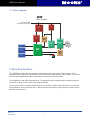
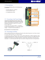
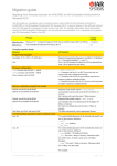
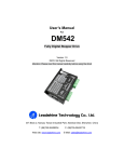
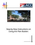
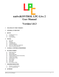
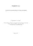
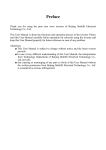
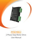
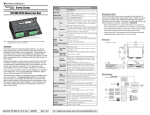
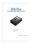
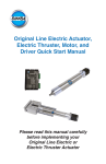
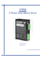
3SR8
3 Phase Step Motor Drive
User Manual
Rev. 1.0
AMP & MOONS’ AUTOMATION
3SR8 User Manual
Contents
1 Introduction................................................................................... 3
1.1 Overview.............................................................................................3
1.2 Features..............................................................................................3
1.3 Block diagram.....................................................................................4
2 Mounting the Drive....................................................................... 4
3 Connections................................................................................. 5
3.1 Connecting to the Power Supply........................................................5
3.2 Connecting to a Motor........................................................................5
3.3 Connecting to the Inputs and Output..................................................6
3.3.1 Step & Direction Inputs.................................................................................6
3.3.3 Fault Output..................................................................................................8
4 Switch Selection........................................................................... 9
4.1
4.2
4.3
4.4
Running Current.................................................................................9
Idle Current.........................................................................................9
Microstepping.....................................................................................9
Self test.............................................................................................10
6 Error Codes................................................................................ 12
7 Reference Materials................................................................... 13
7.1 Mechanical Outline ..........................................................................13
7.2 Specifications....................................................................................13
7.2.1 Electrical Specifications..............................................................................13
7.2.2 Environmental Specifications.....................................................................14
7.3 Torque Curves..................................................................................14
8 Contacting MOONS’................................................................... 15
Rev. 1.0
9/15/2010
2
3SR8 User Manual
1 Introduction
Thank you for selecting the MOONS’ 3SR8 Motor Drive. We hope our commitment to
performance, quality and economy will make a successful motion control project.
1.1 Overview
The 3SR8 series drives are cost-effective, high performance 3 phase step drives. The design is
based on PID current control technology, and features high torque, low noise, and low vibration.
The running current and microstep resolution are switch selectable.
1.2 Features
• Power Supply - operates from a 24 to 75 volt DC power supply
• Output Power - 3 position switch selectable, 8 settings, maximum 7.8 amps peak
• Current Control - advanced digital current control provides excellent high speed torque
• Microstep Resolution - 3 position switch selectable, 8 settings: 1000, 1600, 2000, 3200, 4000,
5000, 6400, 51200 step/rev
• Speed Range - speeds up to 1800 rpm
• Anti Resonance - raises the system-damping ratio to eliminate midrange instability and allow
stable operation throughout the speed range of the motor.
• Auto Setup - measures motor parameters and configures motor current control and antiresonance gain settings
• Microstep Emulation - performs high resolution stepping by synthesizing coarse steps into fine
micro-steps
• Control Modes - Step & Direction (contact factory for CW/CCW pulse option)
• Input Digital Filters - 150K Hz or 2M Hz digital filter for high speed inputs
• Motor Type Select - a 16 bit rotary switch is used to select the desired motor database which
is pre-loaded at the Factory
• Load Inertia Select - as part of the motor database each motor can be selected for use with
low or high load inertia.
• Idle Current - switch selectable for 50% or 90% idle running current reduction 1 second after
the motor stops
• Self Test - switch selectable, the drive will perform a 2 rev, 1 rps, CW/CCW move test
3
Rev. 1.0
9/15/2010
3SR8 User Manual
1.3 Block diagram
3SR8
Block Diagram
24-75VDC(3SR8)
External Power Supply
15V
5V
switching
reg
3.3V
reg
reg
Voltage
Det.
Gate
Drivers
(3)
Rotary code
switch
Optical
Isolation
DSP
MOSFETs
(6)
motor
Over
Current
Det.
8-bit
switch
LED
2 Mounting the Drive
The 3SR8 Step Drive can be mounted on the wide or the narrow side of the chassis. If it is
mounted on the wide side, M3 screws should be used through the four corner holes. For narrow
side mounting applications, M3 screws can be used in the two side holes.
The amplifiers in the drive generate heat. To operate the drive continuously at maximum power
forced air cooling, as from a fan, should be provided.
Never use the drive in a space where there is no air flow or where other devices can cause the
surrounding air to be more than 40 °C. Never put the drive where it can get wet or where metal
particles can fall into it.
Rev. 1.0
9/15/2010
4
3SR8 User Manual
3 Connections
To use the 3SR8 Step Drive, the following items
are needed:
LED
Rotary switch
• A power supply (24 - 75 VDC)
• Pulse & Direction signal
FAULT+/-
OUTOUT+
• A compatible step motor
Logic Connector
STEP+/-,DIR+/-,ENA+/-
Running current,
Step resolution,
Idle current reduction
and Self test.
3.1 Connecting to the Power Supply
If the power supply does not have a fuse on the
output or some kind of short circuit current limiting
device, a fast acting fuse is required. A 7 amp fast
acting fuse should be installed in line with the “+”
power supply lead.
ENEN+
DIRDIR+
STEPSTEP+
SW8
SW7
SW6
SW5
SW4
SW3
SW2
SW1
NC.
Motor Connector
W
V
U
Power Connector
Grounding screw
VV+
Connect the motor power supply “+” terminal to
the drive terminal labeled “V+”. Connect the power
supply “-” to the drive terminal labeled “V-”.
Be careful not to reverse the wires.
3.2 Connecting to a Motor
Never connect the motor to or disconnect it from the drive when the power is on. Never connect
the motor leads to ground or to a power supply.
A 3-phase step motor’s winding is either a star or delta configuration. A delta connection is best
for high speed applications, while a star connection is best for low speed. The 3SR8 drives and
MOONS’ motors are set up for delta connection. Connect the motor leads to the drive screw
terminals U, V, and W. Any two leads may be reversed to change the motor’s running direction.
5
Rev. 1.0
9/15/2010
3SR8 User Manual
3.3 Connecting to the Inputs and Output
3.3.1 Step & Direction Inputs
The 3SR8 Step Drive has two high speed optically isolated inputs called STEP and DIR. They
accept 5 to 24 volt single-ended or differential signals, up to 2MHz. The maximum voltage that can
be applied to the input is 28V.
The motor executes one step with the falling edge of the STEP signal.
The direction of rotation is controlled by the DIR signal level. A low level signal (0 level) will result
in clockwise rotation, and a high level signal (1 level) will result in counterclockwise rotation.
DIR+
+5v to +24v out
Indexer
with
Sinking
Outputs
DIR
3SR8
5 – 24V
High
Speed
Inputs
DIRSTEP+
STEP
STEP-
Connecting to Indexer with Sinking Outputs
Indexer
with
Sourcing
Outputs
DIR
DIR+
COM
DIR-
STEP
STEP+
STEP-
3SR8
5 – 24V
High
Speed
Inputs
Connecting to Indexer with Sourcing Outputs
Indexer
with
Differential
Outputs
DIR+
DIR+
DIR-
DIR-
STEP+
STEP+
STEP-
STEP-
3SR8
5 – 24V
High
Speed
Inputs
Connecting to Indexer with Differential Outputs
Many high-speed indexers have differential outputs
Rev. 1.0
9/15/2010
6
3SR8 User Manual
3.3.2 EN Input
The EN input enables or disables the drive amplifier. It is an optically isolated input that accepts
a 5 to 24 volt single-ended or differential signal. The maximum voltage that can be applied to the
input is 28V.
When EN input is closed, the driver amplifier is deactivated. All the MOSFETs will shut down, and
the motor will be free. When EN input is open, the drive is activated.
When the drive has encountered an error and the fault is removed from system, a falling signal
into the EN input will reset the error status and activate the drive amplifier again.
5 to 24
volt
Power
Supply
+
EN+
Switch or Relay
(closed = logic low)
-
3SR8
Drive
EN-
Connecting the Input to a Switch or Relay
5 to 24
volt
Power
Supply
+
-
EN+
+
NPN
Proximity
Sensor
−
output
3SR8
Drive
EN-
Connecting an NPN type Proximity Sensor to an input
(when prox sensor activates, input goes low)
5 to 24
volt
Power
Supply
+
+
PNP
Proximity
Sensor
-
-
output
EN+
3SR8
Drive
EN-
Connecting an PNP type Proximity Sensor to an input
(when prox sensor activates, input goes low)
7
Rev. 1.0
9/15/2010
3SR8 User Manual
3.3.3 Fault Output
The FAULT Output is optically isolated. The maximum collector current is 100mA, and the
maximum collector to emitter voltage is 30 volts. The output can be wired to sink or source current.
When drive is working normally, the output is open. When the drive encounters an error, the output
closes.
5 – 24 volt
Power Supply
+
3SR8
Drive
-
Load
OUT+
OUT-
Connecting a Sinking Output
5 – 24 volt
Power Supply
+
3SR8
Drive
-
OUT+
COM
OUT-
IN
PLC
Connecting a Sourcing Output
5 – 24 volt
Power Supply
+
3SR8
Drive
-
OUT+
COM
PLC
OUT-
IN
Connecting a Sourcing Output again
5 – 24 volt
Power Supply
relay
+
3SR8
Drive
OUT+
OUT-
1N4935 suppression diode
Driving a Relay
Rev. 1.0
9/15/2010
8
-
3SR8 User Manual
4 Switch Selection
SW1
SW2
SW3
Running current
SW4
SW5
Idle current
SW6
SW7
Microstepping
SW8
Self test
4.1 Running Current
The output current of the 3SR8 Step Drive is set by the SW1, SW2, and SW3 switches and can be
changed as necessary. There are 8 settings available according to the ON/OFF combination of the
switches.
Peak
SW1
SW2
SW3
1.5A
ON
ON
ON
2.0A
OFF
ON
ON
3.0A
ON
OFF
ON
4.0A
OFF
OFF
ON
5.2A
ON
ON
OFF
5.8A
OFF
ON
OFF
7.0A
ON
OFF
OFF
7.8A
OFF
OFF
OFF
3SR8
1.5A
2.0A
3.0A
4.0A
5.2A
5.8A
7.0A
7.8A
4.2 Idle Current
The running current of the 3SR8 drive is automatically reduced anytime the motor isn’t moving
for 1S. Setting the SW4 switch to ON reduces the current to 50% of it running value. Setting
this switch to OFF maintains 90% of the running current. This 90% setting is useful when a high
holding torque is required. To minimize motor and drive heating it is highly recommended that the
idle current reduction feature be set to 50% unless the application requires the higher setting.
4.3 Microstepping
The microstep resolution is set by the SW5, SW6 and SW7 switches. There are 8 settings.
Microstep (step/rev)
SW5
SW6
SW7
1000
ON
ON
ON
1600
OFF
ON
ON
2000
ON
OFF
ON
3200
4000
OFF
ON
OFF
ON
5 6 7
ON
SW5
SW6
SW7
OFF
5000
OFF
ON
OFF
6400
ON
OFF
OFF
51200
OFF
OFF
OFF
9
5 6 7
5 6 7
5 6 7
5 6 7
1000
1600
2000
3200
5 6 7
5 6 7
5 6 7
5 6 7
4000
5000
6400
51200
Rev. 1.0
9/15/2010
3SR8 User Manual
4.4 Self test
Setting switch SW8 to ON after the drive is powered up will cause the drive to perform a self test
move of 2 revolutions both CW and CCW at 1rps. Setting switch SW8 to OFF will disable this
feature.
5 Motor selection
Each position of the 16-bit rotary switch selects a different motor, and
automatically sets the configuration parameters in the drive. The 3SR8 drive
comes programmed with up to 8 typical motors as factory defaults. Drives
can be customized with specially selected motors when required.
The rotary switch also selects a low or high inertia for each motor to allow
for various load conditions. The low setting is 1:1, and the high setting is
10:1. Each motor in the loaded database has unique settings to optimize
the anti-resonance. See the table below.
When the motor selection is changed, the drive power supply will need to be cycled.
Switch Setting
Motor
Switch Setting
Motor
0
-L
8
H
1
24HC4301-L
9
24HC4301-H
2
24HC4303-L
A
24HC4303-H
3
24HC2301-L
B
24HC2301-H
4
24HC3301-L
C
24HC3301-H
5
34HC0302-L
D
34HC0302-H
6
-L
E
-H
7
-L
F
-H
Motor selections ending in L are for low inertia and those ending in H are for high inertia.
Rev. 1.0
9/15/2010
10
3SR8 User Manual
5.1 Recommended motors
21±0.5
24HC Series 1.2°
+0.2
4-Ф5-0.1
49.85±0.20
L
49.85±0.20
0
Ф36-0.05
C
C
60.2Max
15±0.2
1.6±0.2
300±10
6±0.3
C-C(2:1)
Parameters
PART#
7.5±0.1
0
Ф8-0.013
MOTOR
COIL
COIL
MOTOR
MOTOR
MOTOR
MOTOR
WIRING
LENGTH
RESISTANCE /
RESISTANCE /
CURRENT
HOLDING
DETENT
INERTIA
WEIGHT
DIAG
(mm)
PHASE
PHASE
(A)
TORQUE
TORQUE
(g·cm2)
(Kg)
(ohms)
(mH)
(mN·m)
(mN·m)
0.8
24HC2301
E
54.5
0.32
0.76
5.8
900
40
260
24HC3301
E
76.5
0.45
1.30
5.8
1500
70
460
1.3
24HC4303
E
45.5
0.26
0.45
5.8
540
25
180
0.62
49.85±0.20
45.3±0.8
4-M5
49.85±0.20
20±0.3
AA
1.6±0.2
6±0.3
8
490±10
≤0.82
1.6
0
Ф36-0.05
A
60.2Max
38.1±0.5
24HC4301-04
AWG22 UL1007
VIEW A
A-A(2:1)
6.35±0.1
Ink Jet
Label
0
Ф8-0.013
Parameters
PART#
24HC4301-04
MOTOR
COIL
COIL
WIRING
LENGTH
RESISTANCE /
RESISTANCE /
CURRENT
DIAG
(mm)
PHASE
PHASE
(A)
(ohms)
(mH)
6
10.2
E
45.3
11
1.5
MOTOR
MOTOR
MOTOR
MOTOR
HOLDING
DETENT
INERTIA
WEIGHT
(g·cm2)
(Kg)
169
0.62
TORQUE
TORQUE
(mN·m)
(mN·m)
540
25
Rev. 1.0
9/15/2010
3SR8 User Manual
66.5±1
30.2±0.5
85MAX
69.6±0.2
34HC Series1.2°
Ф6.5±0.2
69.6±0.2
C
C
85MAX
Ф73.03±0.025
25±0.2
2±0.2
0
Ф12.7-0.013
90°
11.5±0.1
C-C(2:1)
300±10
10±0.3
11.5±0.1
Parameters
PART#
34HC0302-01
MOTOR
COIL
COIL
WIRING
LENGTH
RESISTANCE /
RESISTANCE /
DIAG
(mm)
E
66.5
PHASE
PHASE
(ohms)
(mH)
0.38
2.4
CURRENT
(A)
5.8
MOTOR
MOTOR
MOTOR
MOTOR
HOLDING
DETENT
INERTIA
WEIGHT
(g·cm2)
(Kg)
1100
1.6
TORQUE
TORQUE
(mN·m)
(mN·m)
2000
100
6 Error Codes
The 3SR8 Step Drive has one bicolor (red/green) LED to indicate status. When the motor is
enabled, the green LED flashes slowly. When the green LED is solid, the motor is disabled. If the
red LED flashes, an error has occurred. Errors are indicated by a combination of red and green
flashes as follows:
Code
Rev. 1.0
9/15/2010
Error
Solid green
Motor disabled
Flashing green
Motor enabled
3 red,2 green
Bad internal voltage
4 red,1 green
Over voltage
4 red,2 green
Under voltage
5 red,1 green
Over current/short circuit
6 red,1 green
Open motor winding
12
3SR8 User Manual
7 Reference Materials
7.1 Mechanical Outline
22.5
33
2-4.5
112
3
118
22.5
22.5
75.5
4-Ф3.5
M3
112
3
Unit:mm
7.2 Specifications
7.2.1 Electrical Specifications
Parameter
Min.
Typ.
Max.
Unit
Power Supply
24
-
75
VDC
Output Current (Peak)
1.5
-
7.8
VDC
STEP/DIR Input Signal Average Forward Current
6
10
15
Amps
Step Frequency
2
-
2M
Hz
STEP Minimum Pulse Width Hi and Low
250
-
-
ns
DIR Minimum Pulse Width
50
-
-
us
Under Voltage Protection
-
20
-
VDC
Over Voltage Protection
-
85
-
VDC
STEP/DIR Input Signal Voltage
4.0
-
28
VDC
OUT Maximum Output Current
-
-
100
mA
OUT Maximum Output Voltage
-
-
30
V
Driver Initialization Time
-
-
2.5
S
13
Rev. 1.0
9/15/2010
3SR8 User Manual
7.2.2 Environmental Specifications
Heat Sinking Method
Natural cooling or fan-forced cooling
Surrounding Air Conditions
Avoid dust, oily mist and corrosive air
Operating Temperature
0 - 40°C (32 - 104°F)
Maximum Ambient Humidity
90% non-condensing
Shock
5.9m/s² maximum
Storage Temperature
-10 - 70°C (14 - 158°F)
7.3 Torque Curves
24HC2301
Drive: 3SR8
Microstep: 10000 steps/rev
Current: 5.8A(Peak)
24HC3301
24V
48V
Drive: 3SR8
Microstep: 10000 steps/rev
Current: 5.8A(Peak)
75V
Torque(N m)
Torque(N m)
. 0.9
0.4
0.2
0
5
10
15
Speed(rps)
20
25
0.6
0.3
0
30
24HC4303
Drive: 3SR8
Microstep: 10000 steps/rev
Current: 5.8A(Peak)
0
5
10
15
Speed(rps)
20
25
30
34HC0302
24V
48V
Drive: 3SR8
Microstep: 10000 steps/rev
Current: 5.8A(Peak)
75V
24V
48V
75V
2.5
0.5
2.0
Torque(N m)
0.4
Torque(N m)
75V
1.2
0.8
. 0.6
. 1.5
. 0.3
0.2
0.1
0
48V
1.5
1.0
0
24V
0
Rev. 1.0
9/15/2010
5
10
15
Speed(rps)
20
25
30
1.0
0.5
0
14
0
5
10
15
Speed(rps)
20
25
30
3SR8 User Manual
8 Contacting MOONS’
Headquarters
168 Mingjia Road, Minhang District,
Shanghai 201107, P.R.China
Tel: +86 (0)21 52634688
Fax: +86 (0)21 52634098
Shenzhen Branch Office
Room 2209, 22/F, Kerry Center, 2008 Renminnan Road, Luohu District,
Shenzhen 518001, P.R.China
Tel: +86 (0)755 25472080
Fax: +86 (0)755 25472081
Beijing Branch Office
Room 202,Unit 2,7th Building, Huilongsen International Science & Technology
Industry Park, No.99,kechuang 14th street, Beijing 101111 ,P.R. China
Tel: +86 (0)10 59755578
Fax: +86 (0)10 59755579
Nanjing Branch Office
Room 302, Building A, Tengfei Creation Center, 55 Jiangjun Road, Jiangning District,
Nanjing 211100, P.R. China
Tel: +86 (0)25 52785841
Fax: +86 (0)25 52785485
Qingdao Branch Office
Room E, 10th Floor, 73 Wangjiao Mansion, Hongkong Middle Road, Shinan District,
Qingdao 266071, P.R. China
Tel: +86 (0)532 85879625
Fax: +86 (0)532 85879512
Europe Branch: Moons' Industries (Europe) S.R.L.
Via Torri Bianche n.1 20059 Vimercate(MB) Italy
Tel: +39 039 62 60 521
Fax: +39 039 96 31 409
Service Center
+86-400-820-9661
15
Rev. 1.0
9/15/2010