1
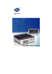
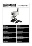
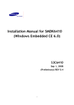
Carlos Daboin
Project Advisor: Dr. Janusz Zalewski
Florida Gulf Coast University
Robotic Arm Connectivity User Manual
August 13, 2009
1. Introduction
The purpose of this document is to give instructions to a new user, how to set up, operate
and program eBox 2300 Robotic Arm Server. The ebox is programmed to operate and use
devices connected to it: web camera, and servo-motors. The specification of devices used in this
project is given in the next sections.
1.1 Hardware required
The equipment used in this project is composed of the following hardware items.
1) eBox 2300 thin client, as a target.[1]
2) Windows PC (XP/VISTA), as a host computer.
3) Logitech Quick Cam Pro 5000.[2]
2
4) Servo Controller for 8 servo motors.[3]
5) Power Supply.[3]
6) Arm Frame for servos.[4]
3
7) Servos Needed.[4]
•
•
•
3 X Servos HS-422
1 X Servo HS-475HB
1 X Servo HS 755HB
8) Cables and connectors.[4]
•
•
•
3 servo extender cable 6"
3 servo extender cable 12"
3 servo extender cable 24"
9) Keyboard and a mouse (single USB cable connection is recommended).
10) Network infrastructure (LAN).
4
1.2
Hardware Assembly
This section present the steps to assemble the robot arm frame with the embedded servo
motors. Then, the section will cover the connectivity between the arm, the controller, and the
eBox 2300. The following steps that explain the assembly of the robotic arm structure are a copy
of the online assembly guides from Lynxmotion website. [4]
1.2.1 Arm Frame Assembly
This section cover all the details to assemble the robotic arm, the section cover the
assembly of the arm base, the arm frame, and the arm gripper.
1.2.1.1 Arm Base
The steps to assemble the rotating arm base are the following:
Step 1.
Insert the stainless steel pins into the plastic
bearings as shown in figure 1.
5x
Figure 1. Plastic Bearings
5
Step 2.
Install the bearings into the base as shown.
They will fit snugly.
Note, the notch in the bottom edge of the base
indicates the back shown in figure 2
Figure 2. Plastic Base
Step 3.
Lay a piece of 400 grit sandpaper on a flat
surface and move the base (upside down) in
small circles on it. This will remove any
imperfections on the bearings. As shown in
figure 3
Figure 3. Plastic Base
6
Step 4.
Figure 4 shows the circle pattern on the
sandpaper and the inset shows the bearings
after any imperfections have been removed.
As shown in figure 4
Figure 4. Base with Bearings Installed
Step 5.
Figure 5 illustrates a typical standard-size
servo with its output horn (the round white
part) at center position. Make sure your servo
looks like the image, and then carefully
remove the servo horn screw and pull the horn
straight off of the servo. As shown in figure 5
Figure 5. Servo Motor
7
Step 6.
Place the servo in the base as shown and
screw it in tightly using four #4 tapping
screws. As shown in figure 6 and figure 7
4x
Figure 7.
Figure 6. Servo Base Installation
Step 7.
Attach the ASB-201 bracket onto the base top,
using four 2-56 x .250" phillips head machine
screws and four 2-56 nuts as shown. Note, the
bracket is included in the arm kit, not the
base kit. As shown in figure 8, and figure 9
4x
4x
Figure 8
Figure 9. Bracket Base Top Installed
8
Step 8.
Add a drop of 3-in-1 oil to each bearing. As
shown in figure 10
Figure 10. Base Top
Step 9.
Install the base top. The hole pattern should
line up as shown in Figure 9, with one line
pointing to the servo wire hole, and all of the
lines pointing between the mounting tabs.
Note, this top piece is manufactured to be a
tight fit. You might have to press very hard.
Attach the top with the servo horn screw. As
shown in figure 11
Figure 11. Base Completed Assembly
9
Step 10.
Route the base servo's cable through the hole
in the back of the base. This will keep the base
level to the mounting surface. As shown in
figure 12
Figure 12. Base Cable Exit
10
1.2.1.2 Arm Frame Assembly
The steps to connect the arm brackets to the servos, and to the arm base are the
following:
Lexan Preparation.
The lexan pieces have a protective covering
that needs to be removed before assembly.
When the laser cuts, the covering melts into
the cut edge which can make removal difficult.
If you gently scrape the cut edge with a flat
blade screwdriver, the covering can easily be
lifted and peeled off. Refer to figure 13.
On smaller pieces the coverings can be more
difficult to remove. If you have trouble you
can gently scrape the cut edge, then use duct
tape to lift the covering off.
Figure 13. Lexan Preparation.
Step 1.
Connect the "C" bracket to the large "C"
bracket as shown. Use two 2-56 x 1/4" screws
and 2-56 nuts as shown in figure 14.
2x
2x
Figure 14. C Brackets
11
Step 2.
Install the mechanical dampening panels as
shown. Use four #2 tapping screws as shown
in figure 15.
Figure 15. C bracket Dampening Connection
Step 3.
Insert the 4-40 x .5" Phillips head screw
through the hole in the multi-purpose bracket
as shown. Secure with a steel nut as shown as
figure 16.
1x
1x
Figure 16. Multi-Purpose Bracket
12
Step 4.
Slide the large "C" bracket end of the bracket
assembly over the screw as shown, and secure
with a nylon insert lock nut. The amount of
friction can be adjusted by tightening or
loosening the lock nut as shown in figure 17.
Start with the nut loose, and if the arm seems
to wobble a bit, you can tighten this joint to
correct the wobble. Caution - don't overtighten this! If the arm is operated with
the mechanical dampeners too tight, the
servo WILL heat up and CAN be damaged!
1x
Figure 17. C Bracket Base Installed
Step 5.
Figure 5 show a typical mega-size servo with
its default servo horn at center position. You
will need to replace this black servo horn with
the round nylon servo horn .
Remove the servo horn screw, being careful to
not rotate the servo horn itself. Pull the servo
horn off, then press the nylon servo horn in
place, as close to the alignment shown as
possible. Replace the servo horn screw.
Make sure your servo looks like figure 18. The
arrows in figure 18 point to the screw holes
you will use.
Figure 18. Servo Motors
13
Step 6.
Attach the HS-755HB servo to the base
bracket as shown using the 3mm hardware;
follow the diagram below. Use two #2 x 1/4"
tapping screws to secure the bracket to the
servo horn. Route the shoulder servo wires
underneath the servo. Plug the servo into
channel 1 on the SSC-32. Carefully rotate the
base to an extreme, and use a wire tie to take
up the slack in the servo cable as shown in
figure 19.
2x
Figure 19. Servo Motor Base Installed
14
Step 7.
Attach two of the tubing connector hubs to the
short side of the "L" brackets, using four 2-56
x .250 screws and 2-56 nuts as shown in
figure 20.
4x
4x
Figure 20. Connector Hubs
Step 8.
Connect the hubs to the 1.50" tube using two
4-40 x .250" screws. Tighten these down
tightly as shown in figure 21.
2x
Figure 21. 1.50” Tube
15
Step 9.
Attach the tubing structure to two MultiPurpose brackets as shown, using four 2-56 x
.250 screws and 2-56 nuts as shown in figure
22.
4x
4x
Figure 22. Multi-Purpose Brackets
Step 10.
Insert the 4-40 x .5" Phillips head screw
through the hole in the multi-purpose bracket
as shown. Secure with a steel nut as shown in
figure 23.
1x
1x
Figure 23. Multi-Purpose Bracket
16
Step 11.
Slide the screw on the forearm assembly
through the dampening discs as shown, and
secure with a nylon insert lock nut. The
amount of friction can be adjusted by
tightening or loosening the lock nut. Start with
the nut loose, and if the arm seems to wobble
a bit, you can tighten this joint to correct the
wobble as shown in figure 24. Caution - don't
over-tighten this! If the arm is operated
with the mechanical dampeners too tight,
the servo WILL heat up and CAN be
damaged!
1x
Figure 24. Arm Frame
Step 12.
Figure 12 illustrates a typical standard-size
servo with its output horn (the round white
part) at center position. Make sure your servo
looks like the image. The arrows in the image
point to the screw holes you will use as shown
in figure 25.
Figure 25. Servo Motor
17
Step 13.
Attach the HS-475HB elbow servo to the
bracket as shown using the 3mm hardware;
follow the diagram below. Use two #2 x 1/4"
tapping screws to secure the bracket to the
servo horn. Route the shoulder servo wires
over the servo. Plug the servo into channel 2
on the SSC-32 as shown in figure 26.
2x
Figure 26. Arm Frame
18
Step 14.
Attach the Little Gripper connector to the
Short "C" bracket using two 2-56 x .250"
screws and 2-56 nuts as shown in figure 27.
2x
2x
Figure 27. Griper Attach Connector
Step 15.
Attach the short "C" bracket to the other Multipurpose bracket as shown as shown in figure
28.
Figure 28. Short C Bracket
19
Step 16.
Attach the HS-422 wrist servo to the bracket
as shown using the 3mm hardware; follow the
diagram below. Use two #2 x 1/4" tapping
screws to secure the bracket to the servo
horn. Route the shoulder servo wires over the
servo as shown in figure 29.
2x
Figure 29. Arm Gripper Frame
20
1.2.1.3 Arm’s Wrist Assembly
This section presents the steps to assemble the robot arm gripper, and how to attach it to
the robotic arm. The steps are the following:
Step 1.
Remove the gripper assembly from the "C"
bracket. Remove the Little Grip from the
Little Grip Connector. Set the "C" bracket
and Little Grip Connector lexan aside; they
will not be used with the wrist rotate as
shown in figure 30.
Figure 30. Arm Gripper
Step 2.
Drop the HS-85BB into the wrist rotate
bracket from the top as shown. Use the
following diagram for attachment
information. Make sure the servo is in center
position and remove the servo horn. Be
careful to not turn the servo shaft as in
figure 31.
Figure 31. C Bracket
21
Step 3.
Attach the Little Grip to the HS-85BB servo
as shown. Push it onto the servo, and secure
with the servo horn screw. Tighten this down
snugly as shown in figure 32.
Figure 32. Gripper Structure
Step 4.
Make sure the HS-422 servo is aligned to
mid-position, and the gripper is halfway
open. Now the servo and gripper will be
aligned correctly. Remove the servo screw
and horn. Slide the servo into the gripper
from the bottom. You may need to wiggle it
a bit to get it seated properly. Use the servo
screw to attach the servo. Tighten this
down, but then unscrew it half a turn. Too
much friction can bind the servo as shown in
figure 33.
Figure 33.
22
Step 6.
Slip the gripper assembly back onto the arm
assembly, and attach with two #2 x .250"
tapping screws. Add a 6" or 12" extender
cable (or both, if necessary) to the wrist
rotate servo, and plug into channel 5 on the
SSC-32. Use wire ties to tidy up the wires as
shown in figure 34.
2x
Figure 34. Arm Gripper Complete Assembly
23
1.2.1.3 Arm Cabling Connection
This section coverts the electric wiring connection from the servo motors installed on the
arm frame to the Phidget multi servo controller pins. The wiring connections have to be
implemented, as shown in figure 35, in order to send instruction commands to the right servo
motor.
4
3
2
1
Figure 35. Multi-Servo Controller Connection Pins
•
0
Pin connects to servo base motor cable.
•
1
Pin connects to servo shoulder motor cable
•
2
Pin connects to servo frame motor cable
•
3
Pin connects to servo hand motor cable
•
4
Pin connects to servo gripper motor cable
24
0
1.3
System Network Connection
The system should be connected as shown in figure 36. This can be done in the steps
discussed below.
Figure 36. System’s Network Diagram
1.3.1
Windows PC host (XP/VISTA) connectivity
1) Connect Windows PC to the network, wireless or wired, but make sure the PC and eBox
2300 are in the same network, because to load operating system image on the eBox,
target, the host has to fetch a boot me request coming from the target to obtain its IP
address. A wired connection to the network was used in this project.
25
1.3.2
eBox 2300 Connectivity
1) Connect power cord, monitor cable, and Ethernet cable to eBox’s back ports. Refer to
Figure 2 to locate ports.
2) Connect the mouse, the keyboard to eBox 2300‘s USB, or PS2 back ports. PS2 is
recommended for keyboard and the mouse connections to allow the tree USB devises to
use the three eBox USB ports. Refer to figure 37 to locate PS2 port.
1 2
3
4
5
6
7
8
1. Power Port
5. Monitor Serial Port
2. Power Switch
6. Ethernet Port
3. PS2 Port
7. USB Port
4. Serial Port
8. USB Port
USB Port Ports
Compact Flash Card Slot
Figure 37. eBox Front and Back Ports
26
3) Connect the servo, and the temperature sensor to the two UBS front ports, and USB cam
to the USB Back port.
The eBox 2300 target IP address is obtained via DNS, and is broadcast to the host after
the eBox 2300 is powered. The target displays a MS –DOS menu when it is powered, then
from this menu the user can chose the preferred way to broadcast the boot me request as
shown in figure 38.
Figure 38. MS-DOS Boot Menu
1.4
Software Installation
For proper operation of the system the following software items have to be installed as
explained in the following steps.
1.4.1
Install MS Visual Studio 2005 or 2007 on the host Windows PC. Visual Studio is needed
to develop C# and VB software applications. It can be obtained from the following site:
http://www.microsoft.com/express/download/ [5]
27
1.4.2
Install Windows Embedded CE 6.0 on the host Windows PC needed to deploy OS
image. It is a 3 month trial license that can be obtained from the following site:
http://www.microsoft.com/downloads/details.aspx?FamilyID=7e286847-6e06-4a0c8cac-ca7d4c09cb56&DisplayLang=en [5]
1.4.2.1
Windows Embedded CE 6.0 platform builder
To install Windows Embedded CE 6.0 platform builder, Visual Studio 2005/2008 must
already be installed onto the develop station (Host). During Windows Embedded CE 6.0
installation program make sure you install ARMV4I CPU support and
ICOP_Vortex86_60B BSP components in the setup installation window.
1.4.2.2
Board Support Package Installation
Board Support Package consists of all necessary Windows CE 6.0 device drivers and
libraries needed by the platform builder to create OS Design and build CE 6.0 image.
Download and install the following file: ICOP_Vortex86_60B_BSP.MSI from
http://www.embeddedpc.net[7 ], or my web site[8]. Then double click on it to start the
installation.
1.4.2.3
VS2005 CoreCon Component Installation
CoreCon is used to establish a link between Windows CE 6.0 target (eBox 2300) and
Visual Studio development station, Host (Windows Pc) to download visual C#/VB
software application onto the target for testing and debugging. Download and install the
following file: CoreCon_x86_VS2005.MSI from http://www.embeddedpc.net[7 ], or my
web site[7]. Then double click on it to start the installation.
28
1.4.3
Install Phidget framework for eBox (Windows Embedded CE), to be able to
communicate with the servo motor and the sensor connected to the eBox. Use a USB Key
drive to get the file to the eBox, and then install on the Windows CE Image running on
the eBox. It can be obtained from the following site:
http://www.phidgets.com/downloads.php?os_id=4 [3]
29
2.
Application Development
This section cover the steps to develop software for the eBox 2300(target), in this project
the OS used was Windows Embedded CE 6.0, and the application was developed on C# under
the .NET framework. However, other operating systems like Linux and programming languages
like Java can be used to develop software for the eBox 2300(target).
2.1
Develop an Operating System Image for the Target, eBox2300
The target needs an operating system to be able to run applications, to communicate with
a network, and to communicate with external devices. The followings steps explain how to
develop a Windows Embedded CE 6.0 operating system image using Microsoft Visual Studio
2005 IDE.
The steps to configure/develop OS image are described below.
1.
Open Visual Studio 2005; select new project.
2.
Select Platform Builder for CE 6.0, then OS Design, and then name it (your OS
name). As shown in figure 39.
Figure 39. New VS 2005 Project Window
30
3.
In the BSP (Board Support Packages), select ICOP_Vortex86_60B: x86 as shown
in figure 40.
Figure 40. Windows Embedded CE 6.0 Design Wizard
4.
In the design templates selection step, select Industrial Device as shown in figure
41.
Figure 41. Windows Embedded CE 6.0 Design Wizard
31
5.
Design template, select Windows Internet Appliance, as shown in figure 42.
Figure 42. Windows Embedded CE 6.0 Design Wizard
6.
In the applications & media selection step, select .NET, Windows Media
Audio/MP3, and Windows Media Video/MEPEG-4 Video as shown in figure 43.
Figure 43. Windows Embedded CE 6.0 Design Wizard
32
7.
In the networking & communications step, select Local Area Network, and Wide
Area Network as shown in figure 44. The OS design wizard will finish after this
step.
Figure 44. Windows Embedded CE 6.0 Design Wizard
Catalog Items View Tap (Enhancing the OS Design)
8.
Select ConMan_86 files components for communication and application
deployment from Third Party directory as shown in figure 45.
33
Figure 45. Windows Embedded CE 6.0 Catalog Items View
9.
Expand Third Party catalog folder, and select Vortex86_Audio from
BSP/ICOP_Vortex86_60b:X86/Device Drivers/Audio; select Vortex86_Display
from BSP/ICOP_Vortex86_60b:X86/Device Drivers/Display, to enable eBox
2300 media interfaces as show in figure 46.
34
Figure 46. Windows Embedded CE 6.0 Catalog Items View
12.
Expand Core OS => CEBASE folder, find and include the following components
to the OS Design.
a.
Applications-End User => CAB File Installer/Uninstaller
This component provides application installation & removal. It’s needed
for application development using Visual Studio .NET 2003 and Visual
Studio 2005.
b.
Core OS Services => USB Host Support => USB Storage Class Driver
This component provides support for hot pluggable USB storage device
supporting most USB flash drive and external USB mass storage device.
13.
Expand Core OS => CEBASE => File Systems and Data Store folder, select and
include the following components to the OS Design.
35
a)
File System – Internal => RAM and ROM File System
b)
Registry Storage => Hive-based Registry
Both of the above two components are needed to support Hive-based registry
implementation. Hive-based registry is used to store and save registry entries changed between
power reset.
14.
From VS2005 IDE, select Build => Configuration Manager. From the Active solution
configuration selection options, select ICOP_Vortex86_60B x86 Release as shown in figure 47.
Figure 47. VS 2005 Configuration Manager.
15.
From VS2005 IDE, select Project => (Your OS Name) Properties
16.
Click to expand Configuration Properties tree on the left side of the screen as shown
Figure 13.
17.
Click to high-light Build Options, a list of Build Options with check boxes will be shown
on the right side of the screen as shown on figure 48.
36
18.
Select Enable eboot space in memory (IMGEBOOT=1). This option adds support for
Ethernet debugging by bundling the Ethernet boot loader in the image as shown in figure 48.
19.
Select Enable ship build (WINCESHIP=1).This option will enable a retail build and
suppress debug messages as shown in figure 48.
20.
Disable KITL – Make sure the Enable KITL (no IMGNOKITL=1) check box is NOT
selected as shown in figure 48.
Figure 48. VS 2005 Property Page
21.
Click to high-light Environment on the left side of screen as shown in figure 49.
37
Figure 49. VS 2005 Property Page
22.
Enter new variable name and set associated value for the following environment variables
as shown in figure 50. Click New; enter variable name, and variable value. Refer to table below:
Variable Name
IMGRAM128
Variable Value
1
Description
Supports hardware with 128MB of
RAM
PRJ_BOOTDEVICE_ATAPI
1
Designates booting from ATAPI
device
PRJ_ENABLE_FSREGHIVE
1
Enables Hive-based registry
function
PRJ_ENABLE_FSMOUNTASR
1
Enables external file to mount as
OOT
root
38
Figure 50. VS 2005 Property Page
23.
From the VS2005 IDE, select Build => Build Solution to build OS image from the OS
Design project.
2.2
Install the WebCam Driver on the Target
The driver used in the project to allow communication between the target operating
system applications and USB camera was develop by Doug Boling, author of Programming
Windows CE, a group of developers, including some from Microsoft [9]. The USB Webcam
driver has been released under the Microsoft Shared Source license. The driver supports cameras
in compliance to the USB Video Standard. The driver has been tested against the Logitech
QuickCam Pro 5000 and video streaming has been tested by WebCam2 application also
developed by Doug Boling under C++.
Driver and test application subproject on Windows Embedded CE 6.0 are used as follow
39
1. In the OS design project, right click on the Subprojects folder locater in the Solution
Explorer tab as shown in figure 51
Figure 51. OS Design Subprojects
2. Select Add New Subproject, then in the wizard window select WCE Application, and for
Subproject name use WebCam as shown in figure 52.
Figure 52. Subproject Wizard Window
3. Click Finish
40
4. The WebCam subproject is only needed to have a location or directory to place the
compiled driver, the compiled WebCam2 application, and all registry entries to
communicate with Logitech Web Cam. The subproject files to place on this project were
put together by Dr. James O. Hamblen, computer engineering professor at Georgia Tech
[10]. Place, the driver and test application in WebCam subproject directory that is
normally located at C:\WINCE600\OSDesigns\Your Project Name\Your Project
Name\WebCam\. To get the driver and the test application files go to my website:
http://satnet.fgcu.edu/~cedaboin/WebCam.zip and click on the eBox 2300 link, then copy
all the files is under the WebCam zip file.
5. Replace the files created by the IDE in the WebCam subproject directory with the ones
you copy from my web site. Finally, right click on the subproject, and select build to add
this component to the OS image.
2.3
Building SDK (Software Development Kit) on the Host
To create CE 6.0 applications using Visual Studio 2005 and establish a connection to
download applications to the eBox-2300 for testing and debug, VS2005 needs a SDK for eBox2300. Follow these steps in the windows embedded CE image project file (Your OS design
project in Visual Studio).
1. From VS2005 IDE, select Solution Explorer Tab=> SDKs Directory. Right click on it
and select Add New SDK as shown in figure 53.
41
Figure 53. Solution Explorer Window
2. Enter Your SDK Name as the name for the SDK as shown in Figure 54.
3. Fill in the company name and company website information as shown in figure 54.
Figure 54. SDK Property Page
42
4. On the SDK property page, click on Install and enter MSI folder path and MSI file
name on the right side as shown in figure 55.
5. Use the default path, and enter Your SDK Name.msi as the file name as shown in
figure 55.
Figure 55. SDK Property Page
6. On the SDK Property Page, click on Development Languages and select both Native
and Managed development support as shown in figure 56.
43
Figure 56. SDK Property Page
7. Click on the Apply and then OK button.
8. From VS2005 IDE, select Build => Build All SDKs to build and generate SDK
installation file.
9. A SDK with the file name “Your SDK Name.msi” is generated in the following
directory: \WINCE600\OS Designs\Your Project Name\Your Project
Name\SDKs\SDK1\MSI\Your SDK Name
10. To install this SDK in VS2005, locate SDK file at \WINCE600\OS Designs\Your
Project Name\Your Project Name\SDKs\SDK1\MSI\.Your SDK Name. Then double
click on it
44
2.4
Software Application in Visual C#
2.4.1
Developing a Target Application
Visual Studio 2005 can be used to develop software applications for Windows Embedded
CE 6.0. This section shows how to start the development of Visual C# software applications.
1.
From Visual Studio 2005 IDE, Select File => New => Project, the following new
project screen will appear as shown in figure 57.
2.
Expand Visual C# and Smart Device folders, to select Windows CE 5.0 as shown
in figure 57.
3.
Then, select => Device Application, and enter Your Application Name as the
project name as shown in figure 57.
4.
Click OK.
Figure 57. New Project Window
45
Now, you can start developing any Windows Embedded Visual C# application; that is
writing the actual code. The project source code for the target can be obtained from my website:
http://satnet.fgcu.edu/~cedaboin/WebCam.zip [8]
2.4.2
Developing the Host Application
Developing the host application follows similar steps to developing the target application.
In Visual Studio 2005, follow these steps:
1.
From Visual Studio 2005 IDE, Select File => New => Project, the following new
project screen will appear as shown in figure 58.
2.
Expand Visual C#, to select Windows as shown in figure 58.
3.
Then, select => Windows Application, and enter Your Application Name as the
project name as shown in figure 58.
4.
Click OK.
Figure 58. New Project Window
46
Now, you can start developing any Windows Visual C# application. The project source
code for the host can be obtained from my website:
http://satnet.fgcu.edu/~cedaboin/WebCam.zip [8]
47
3.
Application Deployment
Once the system is configured as described in Section 1, and the application developed as
explained in Section 2, the software is ready for deployment. There are two essential steps in
deploying the application on the target; the Windows Embedded image deployment and the
server application deployment.
3.1
Windows Embedded Image Deployment
The following steps have to be followed for deployment:
1. From VS2005 IDE, select Target => Connectivity Options => Add Devise => name your
target device, e.g. eBox 2300, and click on the Add button to continue. Then From the
Target Device Connectivity Options screen, make sure Debugger set to KdStub, and
clicks on one of the Settings buttons to bring up the Ethernet Download Settings screen.
Refer to figure 59.
Figure 59. VS 2005 Target Device Connectivity Options
48
2. Turn on power and boot up eBox-2300. It will boot to DOS and provide the menu
selections. Select 3, or 4 menu option for an image that will load from an Ethernet
connection.
3. After eBox-2300 boots-up and sends a boot-me request, the Ethernet Download Settings
dialog screen, select device ID listed in the Active target devices list box. Refer to figure
60.
Figure 60. VS 2005 Ethernet Download Settings
4. Click and highlight the device ID listed in the Active Devices window
49
5.
Click Ok to continue
6. Turn off the eBox, and the turn on power and boot up eBox-2300, from the DOS menu
select 2,3,or 4 for and Ethernet connection.
7. From VS2005 IDE select Target => Attach Device. You should get a window that looks
like figure 61.
Figure 61. Download Image Window
8. After the image download process is completed, eBox-2300 will load the Windows CE
image.
9.
From eBox-2300 desktop, with CE 6.0 image running on the eBox 2300, double click on
open the Windows folder on OS desktop.
10. From the Windows folder, double click on ConmanClient2.exe, and double click on
cMaccept.exe to launch CoreCon_x86_VS2005 connection service.
CoreCon_x86_VS2005 allows remote C# application remote debugging.
50
3.2
C# application deployment to eBox 2300
Once the image has been loaded on the eBox target, the application on itself has to be
deployed, as described in the following steps:
1. Set the target device to Your eBox SDK name on the target device drop down menu as
shown in figure 62.
Figure 62 VS 2005 Target Device
2.
Select Tools => Options
3.
Click to expand the “Device Tools” folder and select the “Devices” sub-folder.
4.
Select Your eBox SDK name from the list of available platform in the Show devices
for platform combo text box as shown in figure 63.
51
Figure 63. VS 2005 Option Window
5. Click on the Properties button to bring up Your SDK Name x86 Device Properties
setting screen as shown in figure 64.
Figure 64. VS 2005 Device Properties
52
6. Click on the Configure button to bring up Configure TCP/IP Transport as shown in
figure 65.
7. Select Use specific IP address and enter eBox 2300’s IP address as shown in figure 65.
Figure 65. Configure TCP/IP Transport
8. Select Tools => Connect to device
9. Select Your eBox SDK name from the list of available devices, and click on the
Connect button as shown in figure 66.
53
Figure 66. VS 2005 Connect Device Window
10.
The eBox 2300 must have the OS image already loaded, then go to
Device=>Windows, and double click on , files. This to files allow application remote
debugging.
11.
Select Debug => Start Debugging to bring up the Deploy screen as shown in figure
67.
Figure 67. VS 2005 Deploy Window
54
11.
Select Your eBox SDK name and click Deploy as shown in Figure 67.
For a complete set of steps including details of the Window Embedded CE installation
and deployment; refer to eBox2300_CE60_JumpStart [10] file that comes with the eBox 2300,
or can be obtained from my web site [8].
55
4.
Client Application and Testing (Host).
The client software, which accesses the server running on the target, can be developed
completely independently. The initial step to start is to open an application project in Visual
Studio IDE on the host, and proceed from there.
The source code of the current version of the client can be downloaded from my website:
http://satnet.fgcu.edu/~cedaboin/ebox2300.html [8].
To run the client, download the MSI files from my website, then double click on MSI file
icon after downloaded. The two MSI files are different; one client Robot Arm Gamepad has the
capability to control the arm with an Xbox 360 controller. The other client Robot Arm can
control the arm, but does not the capability to control the arm with a gamepad. The GUIs images
shown in figure 68 will appear on the screen. Then, click the connect button to communicate
with the target and get the webcam image, and robotic arm control.
Figure 68. Clint application’s GUI running on the Host
56
5.
References
[1] "EBox-2300." EBox 2300 CompacT PC. Embeddedpc.net. 1 Oct. 2008
<http://www.embeddedpc.net/eBox2300/tabid/110/Default.aspx>.
[2] "Logitech QuickCam Pro 5000 WebCam." Amazon.com: Logitech QuickCam Pro
5000 WebCam: Electronics. Amazon.com. 20 Oct. 2008
<http://www.amazon.com/Logitech-QuickCam-Pro-5000WebCam/dp/B000BDH2XY>.
[3] "Products for USB Sensing and Control." Phidgets Inc. - Unique and Easy to Use
USB Interfaces. Phidgets.com. 1 Feb. 2009 <http://www.phidgets.com/>.
[4] "Products." Robotic Arms. Lynxmotion, Inc. Web. 20 June 2009.
<http://www.lynxmotion.com/Category.aspx?CategoryID=27>.
[5] "Visual Studio Express Editions." Visual Studio Express Editions. 2008. 12 Sept.
2008 <http://www.microsoft.com/express/2005/>.
[6] "Windows Embedded Developer Center." Microsoft Windows Embedded Developer
Center. 10 Sept. 2008. 10 Sept. 2008 <http://msdn.microsoft.com/enus/embedded/default.aspx>.
[7] "ICOP_Vortex86_60B_BSP.msi." BSP, Driver & Utils for Windows Embedded CE
6.0. 8 Sept. 2008
<http://www.embeddedpc.net/Download/WindowsEmbeddedCE60Downl
oad/tabid/113/Default.aspx
[8] Daboin, Carlos. "System for Remote Measurement and Control." System for Remote
Measurement and Control. 12 Mar. 2009. Florida Gulf Coast University.
12 Apr. 2009 <http://satnet.fgcu.edu/~cedaboin/ebox2300.html>.
57
[9] Boling, Doug. "Webcam100.zip." Windows CE Webcam Project. 15 Oct. 2007.
Codeplex.com. 10 Oct. 2008
<http://www.codeplex.com/cewebcam/Release/ProjectReleases.aspx?Rele
aseId=7751>.
[10] Hamblen, James O. "WebCam/." Index of
/~hamblen/wemap/eBox4300/Subprojects_C_C++. 11 Apr. 2008. Georgia
Tech. 1 Nov. 2008
<http://users.ece.gatech.edu/~hamblen/wemap/eBox4300/Subprojects_C_
C++/>.
[11] Phung, Samuel. "EBox-2300 Windows Embedded CE 6.0 Jump Start Guide." EBox2300 Windows Embedded CE 6.0 Jump Start Guide. ICOP Technology
Inc. 01 Oct. 2008
<http://www.embeddedpc.net/download/doc/eBox2300_CE60_JumpStart
_Rev3.5.pdf>.
58