1
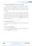
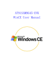
Installation Manual for SMDK6410
(Windows Embedded CE 6.0)
S3C6410
Sep 1, 2008
(Preliminary) REV 0.4
1
Important Notice
The information in this publication has been carefully
checked and is believed to be entirely accurate at
the time of publication. Samsung assumes no
responsibility, however, for possible errors or
omissions, or for any consequences resulting from the
use of the information contained herein.
Samsung reserves the right to make changes in its
products or product specifications with the intent to
improve function or design at any time and without
notice and is not required to update this
documentation to reflect such changes.
This publication does not convey to a purchaser of
semiconductor devices described herein any license
under the patent rights of Samsung or others.
Samsung makes no warranty, representation, or
guarantee regarding the suitability of its products for
any particular purpose, nor does Samsung assume any
liability arising out of the application or use of any
product or circuit and specifically disclaims any and
all liability, including without limitation any
consequential or incidental damages.
"Typical" parameters can and do vary in different
applications. All operating parameters, including
"Typical" must be validated for each customer
application by the customer's technical experts.
Samsung products are not designed, intended, or
authorized for use as components in systems
intended for surgical implant into the body, for other
applications intended to support or sustain life, or
for any other application in which the failure of the
Samsung product could create a situation where
personal injury or death may occur.
Should the Buyer purchase or use a Samsung product
for any such unintended or unauthorized application,
the Buyer shall indemnify and hold Samsung and its
officers, employees, subsidiaries, affiliates, and
distributors harmless against all claims, costs,
damages, expenses, and reasonable attorney fees
arising out of, either directly or indirectly, any claim
of personal injury or death that may be associated
with such unintended or unauthorized use, even if
such claim alleges that Samsung was negligent
regarding the design or manufacture of said product
S3C6410 RISC Microprocessor
Installation Manual
Copyright © 2007-2008 Samsung Electronics Co.,Ltd.
All rights reserved. No part of this publication may
be reproduced, stored in a retrieval system, or
transmitted in any form or by any means, electric or
mechanical, by photocopying, recording, or
otherwise, without the prior written consent of
Samsung Electronics Co.,Ltd.
Samsung Electronics Co., Ltd.
San #24 Nongseo-Dong, Giheung-Gu
Yongin-City Gyeonggi-Do, Korea
446-711
Home Page: http://www.samsungsemi.com/
E-Mail: [email protected]
Printed in the Republic of Korea
Preliminary product information describe products that are in development,
for which full characterization data and associated errata are not yet available.
Specifications and information herein are subject to change without notice.
Revision History
Revision No
Description of Change
Refer to
Author(s)
Date
-
Woosuk
Chung
2008-03-27
Woosuk
Chung
2008-04-29
0.0
Preliminary draft
0.1
Revised for Pre-Beta and
WinCE6.0 R2 BSP
0.2
Revised for Fusing Step
Jiwon Kim
2008-07-15
0.3
KITL setup procedure is
added
Jiwon Kim
2008-08-05
0.4
SOC Folder Structure changes
is applied.
Jiwon Kim
2008-09-01
NOTE: REVISED PARTS ARE WRITTEN IN BLUE.
i
SMDK6410 WINCE6.0 INSTALLATION MANUAL
Contents
1
OVERVIEW.................................................................................................................................................. 1
2
COPYING BSP AND SETTING UP VISUAL STUDIO 2005 ................................................................. 2
3
CREATING A NEW OS DESIGN.............................................................................................................. 5
4
BUILDING OS IMAGE – WITHOUT KITL .......................................................................................... 13
5
RUNNING NK.NB0 IMAGE..................................................................................................................... 26
6
FUSING WINCE IMAGE TO NAND FLASH VIA USB....................................................................... 33
7
BUILDING AND RUNNING OS IMAGE – WITH KITL ..................................................................... 59
7.1
8
ii
USB SERIAL KITL ................................................................................................................................ 61
APPENDIX I – DIP SWITCH SETTINGS FOR BOOTING MODE ................................................... 71
SMDK6410 WINCE6.0 INSTALLATION MANUAL
Figures
Figure 2-1 SMDK6410 BSP Files .................................................................................... 2
Figure 2-2 Visual Studio 2005 Window ........................................................................... 4
Figure 3-1 Creating New Project ................................................................................. 5
Figure 3-2 New Project for WinCE6.0 ............................................................................ 6
Figure 3-3 Windows Embedded CE 6.0 OS Design Wizard ..................................................... 6
Figure 3-4 Windows Embedded CE 6.0 OS Design Wizard – Step 1 .......................................... 7
Figure 3-5 Windows Embedded CE 6.0 OS Design Wizard – Step 2 .......................................... 8
Figure 3-6 Windows Embedded CE 6.0 OS Design Wizard – Step 3 .......................................... 9
Figure 3-7 Windows Embedded CE 6.0 OS Design Wizard – Step 4 ........................................ 10
Figure 3-8 Windows Embedded CE 6.0 OS Design Wizard – Step 5 ........................................ 11
Figure 3-9 Windows Embedded CE 6.0 OS Design Wizard – Step 6 ........................................ 12
Figure 4-1 Catalog Items View .................................................................................. 13
Figure 4-2 Build Mode in Visual Studio 2005 .................................................................. 14
Figure 4-3 Adding File System and Data store Item to OS Design ......................................... 15
Figure 4-4 Adding Graphics and Multimedia Technologies Item to OS Design ........................... 16
Figure 4-5 Adding Core OS Services Item to OS Design...................................................... 17
Figure 4-6 Adding Core OS Services Item to OS Design...................................................... 18
Figure 4-7 Adding Device Drivers Item to OS Design......................................................... 19
Figure 4-8 Adding Networking Item to OS Design ............................................................ 20
Figure 4-12 Properties of OS Design............................................................................ 21
Figure 4-13 Selecting Language in the Property Pages Window ........................................... 22
Figure 4-14 Removing KITL Setting in OS Design Properties Window ..................................... 22
Figure 4-15 Build OS Design ..................................................................................... 23
Figure 4-16 Building Process..................................................................................... 24
Figure 4-17 After Building the OS Image ...................................................................... 25
Figure 5-1 DNW Window.......................................................................................... 26
Figure 5-2 UART/USB Options ................................................................................... 27
Figure 5-3 DNW Window after Board Power ON .............................................................. 28
Figure 5-4 USB OTG Mon Menu .................................................................................. 29
Figure 5-5 Download & Run...................................................................................... 30
Figure 5-6 Selecting NK.nb0 for Download .................................................................... 31
Figure 5-7 Downloading Status of NK.nb0 ..................................................................... 32
Figure 6-1 DNW Window.......................................................................................... 33
Figure 6-2 UART/USB Options ................................................................................... 34
Figure 6-3 DNW Window after Board Power ON .............................................................. 35
Figure 6-4 usb OTG Mon menu .................................................................................. 36
Figure 6-5 Download & Run...................................................................................... 37
Figure 6-6 Selecting EBOOT.nb0 for Download ............................................................... 38
Figure 6-7 After EBOOT.nb0 Download ........................................................................ 39
Figure 6-8 Ethernet Boot Loader Configuration - Before ................................................... 40
Figure 6-9 Ethernet Boot Loader Configuration - After ..................................................... 41
Figure 6-10 Preparing to download image through USB..................................................... 42
Figure 6-11 Selecting STEPLDR.nb0 for Download ........................................................... 43
Figure 6-12 Messages via UART Port after STEPLDR.nb0 Download ....................................... 44
Figure 6-13 DNW Window after reset .......................................................................... 45
Figure 6-14 Selecting EBOOT.nb0 for Download ............................................................. 46
Figure 6-15 After EBOOT.nb0 Download....................................................................... 47
Figure 6-16 Ethernet Boot Loader Configuration............................................................. 48
Figure 6-17 Preparing to download image through USB..................................................... 49
Figure 6-18 Selecting EBOOT.bin for Download .............................................................. 50
Figure 6-19 Messages via UART Port after EBOOT.bin Download .......................................... 51
Figure 6-20 DNW Window after reset .......................................................................... 52
Figure 6-21 Selecting EBOOT.nb0 for Download ............................................................. 53
Figure 6-22 After EBOOT.nb0 Download....................................................................... 54
Figure 6-23 Ethernet Boot Loader Configuration............................................................. 55
.
iii
SMDK6410 WINCE6.0 INSTALLATION MANUAL
Figure 6-24 Preparing to download image through USB.....................................................
Figure 6-25 Selecting NK.bin for Download ...................................................................
Figure 6-26 Messages via UART Port during NK.bin Download .............................................
Figure 7-1 OSDesign Properties .................................................................................
Figure 7-2 Property Pages for KITL .............................................................................
Figure 7-3 Build OSDesign........................................................................................
Figure 7-4 DNW Window after reset............................................................................
Figure 7-5 Selecting EBOOT.nb0 for Download ...............................................................
Figure 7-6 After EBOOT.nb0 Download ........................................................................
Figure 7-7 Ethernet Boot Loader Configuration .............................................................
Figure 7-8 Target Connectivity Option ........................................................................
Figure 7-9 Target Device Connectivity Options Window Before Transport Select ......................
Figure 7-10 Target Device Connectivity Options Window After Transport Select ......................
Figure 7-11 Attach Device .......................................................................................
Figure 7-12 Messages via UART Port............................................................................
Figure 7-13 Visual Studio 2005 Window after USB Serial KITL connected................................
iv
56
57
58
59
60
61
63
64
64
65
66
67
67
68
69
70
SMDK6410 WINCE6.0 INSTALLATION MANUAL
1 Overview
This Installation Manual guides you to install the Samsung SMDK6410 Windows Embedded CE 6.0 BSP.
The manual explains the following topics:
•
Copying BSP and Setting up Platform Builder
•
Creating a New OS Design
•
Building OS Image – Without KITL
•
Running NK.nb0 Image
•
Fusing WinCE Image on NAND Flash via USB
The detail information of each topic is explained in the following chapters.
.
1
SMDK6410 WINCE6.0 INSTALLATION MANUAL
2 Copying BSP and Setting up Visual Studio 2005
In this chapter, you can understand how to copy the Samsung SMDK6410 Windows Embedded CE 6.0
BSP and setup the Platform Builder. There are two distribution types. One is MSI (MS installer)
distribution, another one is old-style zip-archived distribution. With MSI, you can just run the MSI
file, and then follow the instruction on installer. Here are contents only for old-style zip-archived.
1. To start the BSP installation, Extract zip-archived file into $(WINCEROOT)\PLATFORM. See the
picture describes folder structure. In archives, PLATFORM folder has two sub folders. One is
SMDK6410, and another one is COMMON/SRC/SOC/S3C6410_SEC_V1.
For example, copy extracted SMDK6410_WinCE60_XX_XX\PLATFORM BSP folder to
X:\WINCE600\PLATFORM directory on your host PC. Make sure that catalog file and batch file
in X:\WINCE600\PLATFORM\SMDK6410 directory has the same name as that of the BSP, i.e.
SMDK6410.pbcxml and SMDK6410.bat.
Note: About PQOAL & SOC Folder Structure, Please refer to porting guide, If you don’t know the
difference between PQOAL and non-PQOAL structure, read first porting guide.
Figure 2-1 SMDK6410 BSP Files
2
SMDK6410 WINCE6.0 INSTALLATION MANUAL
.
3
SMDK6410 WINCE6.0 INSTALLATION MANUAL
2. To start SMDK6410 Windows Embedded CE 6.0 BSP Porting, on your host PC click Start, point to
All Programs, point to Microsoft Visual Studio 2005 and then click on Microsoft Visual Studio
2005. The following window appears on your screen.
Figure 2-2 Visual Studio 2005 Window
4
SMDK6410 WINCE6.0 INSTALLATION MANUAL
3 Creating a New OS Design
In this chapter, you can understand how to create a new OS Design using the Visual Studio 2005.
1. On the File menu in the Visual Studio 2005 window, click New /Project as shown in figure 3-1.
Figure 3-1 Creating New Project
.
5
SMDK6410 WINCE6.0 INSTALLATION MANUAL
2. The following window appears on your screen. Click OK button to continue.
Figure 3-2 New Project for WinCE6.0
3. The Windows Embedded CE 6.0 OS Design Wizard appears on your screen as below figure.
Click NEXT button to continue .
Figure 3-3 Windows Embedded CE 6.0 OS Design Wizard
6
SMDK6410 WINCE6.0 INSTALLATION MANUAL
4. The Board Support Packages (BSPs) window appears on your screen. Select SMDK6410:
ARMV4I and then click Next button.
Figure 3-4 Windows Embedded CE 6.0 OS Design Wizard – Step 1
.
7
SMDK6410 WINCE6.0 INSTALLATION MANUAL
5. The Design Template Wizard window appears on your screen. Please select PDA Device from
Available design templates list and then click Next button.
Figure 3-5 Windows Embedded CE 6.0 OS Design Wizard – Step 2
8
SMDK6410 WINCE6.0 INSTALLATION MANUAL
6. The Design Template Variants window appears on your screen. Please select Mobile Handheld
from Available design Variants list and then click Next button.
Figure 3-6 Windows Embedded CE 6.0 OS Design Wizard – Step 3
.
9
SMDK6410 WINCE6.0 INSTALLATION MANUAL
7. The following window appears on your screen. Here you can select the Application & Media you
want to include in your platform and then click Next button.
Figure 3-7 Windows Embedded CE 6.0 OS Design Wizard – Step 4
10
SMDK6410 WINCE6.0 INSTALLATION MANUAL
8. The Networking & Communications wizard window appears on your screen. Click Finish button.
Figure 3-8 Windows Embedded CE 6.0 OS Design Wizard – Step 5
.
11
SMDK6410 WINCE6.0 INSTALLATION MANUAL
9. The following window appears on your screen. Please read all the security warnings and then
click Acknowledge button.
Figure 3-9 Windows Embedded CE 6.0 OS Design Wizard – Step 6
12
SMDK6410 WINCE6.0 INSTALLATION MANUAL
4 Building OS Image – Without KITL
1. In the Visual Studio 2005 window on your host PC, you can see the new OS Design along with
its various sub-directories on the left hand side Catalog Items View as shown in figure 4-1. Here,
you can choose items what you want to include in your OS design. The chosen items in this
instruction are only for sample purpose.
Figure 4-1 Catalog Items View
.
13
SMDK6410 WINCE6.0 INSTALLATION MANUAL
2. You can change build mode
SMDK6410_ARMV4I Release.
(release
or
debug
mode)
as
Figure 4-2 Build Mode in Visual Studio 2005
14
below
figures.
Select
SMDK6410 WINCE6.0 INSTALLATION MANUAL
3. Expand File Systems and Data Store node in the Core OS node in Catalog Items View, then
select some items as shown in the figure below.
File System-RAM and ROM File System
Registry Storage-Hive-based Registry(recommended) or RAM-based Registry
Storage Manager-Binary Rom Image file System
Storage Manager-exFAT File System
Storage Manager-Storage Manager Control Panel Applet
Storage Manager-TFAT File System
Figure 4-3 Adding File System and Data store Item to OS Design
.
15
SMDK6410 WINCE6.0 INSTALLATION MANUAL
4. Expand Core OS node in Catalog Items View window, then expand Graphics and Multimedia
Technologies. Select some items as shown in the figure below.
Graphics-Direct3D Mobile
Graphics-DirectDraw (Required for Display Driver)
Media-Video Codecs and Renderers-WMV/MPEG-4 Video Codec (Required for MFC)
Media-Windows Media Player (Required for MFC)
Media-DirectShow Video Capture (Required for Camera)
Figure 4-4 Adding Graphics and Multimedia Technologies Item to OS Design
16
SMDK6410 WINCE6.0 INSTALLATION MANUAL
5. Expand Core OS Services node in the Core OS node in Catalog Items View, then expand USB
Host Support. Select some items as shown in the figure below.
USB Function Driver
USB Host Support
USB Human Input Device(HID) Class Driver (recommended)
USB HID Keyboard and Mouse
USB Storage Class Driver
Figure 4-5 Adding Core OS Services Item to OS Design
.
17
SMDK6410 WINCE6.0 INSTALLATION MANUAL
6. Expand Applications and Services Development node in Catalog Items View window, then
expand OBEX Server.
Select OBEX File Brower and OBEX Inbox.
Figure 4-6 Adding Core OS Services Item to OS Design
18
SMDK6410 WINCE6.0 INSTALLATION MANUAL
7. Expand Device Drivers node in Catalog Items View window, then expand USB Function. Select
Some Items as shown in the figure below.
USB Function Clients-Mass Storage
USB Function Clients-serial
Select SD Bus Driver in SD, SD Memory in SDIO and Windows Embedded CE Test Kit.
Figure 4-7 Adding Device Drivers Item to OS Design
.
19
SMDK6410 WINCE6.0 INSTALLATION MANUAL
8. Expand Device Drivers node in Catalog Items View window, then expand Networking. Select
Serial Infrared (SIR) as shown in the figure below.
Figure 4-8 Adding Networking Item to OS Design
20
SMDK6410 WINCE6.0 INSTALLATION MANUAL
9. On the top of Visual Studio 2005, You can see the Project menu as below figure.
And then select Properties...
Figure 4-12 Properties of OS Design
.
21
SMDK6410 WINCE6.0 INSTALLATION MANUAL
10. The OS Design Properties Pages window appears on your screen. Select Locale tab and click
Clear All button. It clears all the language settings in your platform. Now select English
(United States) as shown in figure 4-10.
Figure 4-13 Selecting Language in the Property Pages Window
11. Now please uncheck the square boxes Enable KITL (no IMGNOKITL=1) in the Build Options
Properties in OS Design Properties Pages window and then click OK button.
Figure 4-14 Removing KITL Setting in OS Design Properties Window
22
SMDK6410 WINCE6.0 INSTALLATION MANUAL
12. On the Build menu, click Build OSDesign1 as shown in figure 4-12 to build the Eboot and OS
image.
Figure 4-15 Build OS Design
.
23
SMDK6410 WINCE6.0 INSTALLATION MANUAL
13. The arrow pointing to the icon in the following figure indicates the Building process.
Building
Process
Figure 4-16 Building Process
Note: Building process may take some time depending on your system capability. So, please wait
for the build process to be completed. It might take around 1 hour.
24
SMDK6410 WINCE6.0 INSTALLATION MANUAL
14. After completion of build process, following messages appear as shown in figure 4-12.
EBOOT.nb0, EBOOT.bin, STEPLDR./nb0, NK.bin and NK.nb0 are now available in
X:\WINCE600\OSDesigns
\[OS
Design
Name]\
[OS
Design
Name]\RelDir\SMDK6410_ARMV4I_Release directory.
Figure 4-17 After Building the OS Image
.
25
SMDK6410 WINCE6.0 INSTALLATION MANUAL
5 Running NK.nb0 Image
In this chapter, you can understand how to download and run the NK.nb0 image.
1. Before you download the WinCE Image through the USB, you must have 6410_OtgMon.bin
image on your AMD Flash. (The image was already fused on your AMD Flash in the board before
release)
2. Configure DIP switch CFG0 on the CPU Board and CFGB1 on the CPU board properly for booting
from AMD Flash. (For more information, Read SMDK6410 Board User's Manual in Document
folder...)
3. Please install the USB Driver and DNW application on your host PC.
4. After installing the USB driver, run dnw.exe on the host PC. The following window appears on
your screen.
Figure 5-1 DNW Window
26
SMDK6410 WINCE6.0 INSTALLATION MANUAL
5. On the Configuration menu, click Options to set the UART/USB options. The following window
appears on your screen. Select Baud Rate and COM Port as shown in figure 5-2, enter the
download address as 0x50100000 and then click OK button.
Figure 5-2 UART/USB Options
.
27
SMDK6410 WINCE6.0 INSTALLATION MANUAL
6. On the Serial Port menu, click Connect. Switch ON the board and then press any key. The DNW
window appears as shown in figure 5-3.
Figure 5-3 DNW Window after Board Power ON
28
SMDK6410 WINCE6.0 INSTALLATION MANUAL
7. Press any key to see USB OTG Mon menu. Now DNW window appears as shown below.
Figure 5-4 USB OTG Mon Menu
.
29
SMDK6410 WINCE6.0 INSTALLATION MANUAL
8. Enter 0 to download and run the Image on the board. DNW window appears as shown in figure
5-5.
Figure 5-5 Download & Run
30
SMDK6410 WINCE6.0 INSTALLATION MANUAL
9. On the USB Port menu, click Transmit and the following window appears on your screen. Select
NK.nb0 from X:\WINCE600\OSDesins\[OS Design name]\[OS Design
name]\RelDir\SMDK6410_ARMV4I_Release directory and then click Open button.
Figure 5-6 Selecting NK.nb0 for Download
.
31
SMDK6410 WINCE6.0 INSTALLATION MANUAL
10. Once download begins, a download status bar appears on your screen as shown in figure 5-7.
After NK.nb0 download is over, Windows Embedded CE 6.0 boots on the target Board
Figure 5-7 Downloading Status of NK.nb0
32
SMDK6410 WINCE6.0 INSTALLATION MANUAL
6 Fusing WinCE Image to NAND Flash via USB
In this chapter, you can understand how to fuse WinCE image to NAND Flash via USB.
1. Before you download the WinCE Image through the USB, you must have 6410_OtgMon.bin
image on your AMD Flash. (The image was already fused on your AMD Flash in the board before
release)
2. Configure CFG0 DIP switch on the CPU Board and CFGB1 on the CPU board properly for booting
from AMD Flash. (For more information, Read SMDK6410 Board User's Manual in Document
folder...)
3. Please install the USB Driver and DNW application on your host PC.
4. Run dnw.exe on the host PC. The following window appears on your screen.
Figure 6-1 DNW Window
.
33
SMDK6410 WINCE6.0 INSTALLATION MANUAL
5. On the Configuration menu in the DNW window, click Options to set the UART/USB options.
The following window appears on your screen. Select Baud Rate and COM Port as shown in
figure 7-4, enter the download address as 0x50030000 and then click OK button.
Figure 6-2 UART/USB Options
34
SMDK6410 WINCE6.0 INSTALLATION MANUAL
6. On the Serial Port menu, click Connect. Switch ON the board and then press any key. The DNW
window appears as shown in figure 6-3.
Figure 6-3 DNW Window after Board Power ON
.
35
SMDK6410 WINCE6.0 INSTALLATION MANUAL
7. Press any key to see USB OTG Mon menu. Now DNW window appears as shown below.
Figure 6-4 usb OTG Mon menu
36
SMDK6410 WINCE6.0 INSTALLATION MANUAL
8. Enter 0 to download and run the Image on the board. DNW window appears as shown in figure
6-5.
Figure 6-5 Download & Run
.
37
SMDK6410 WINCE6.0 INSTALLATION MANUAL
9. On the USB Port menu, click Transmit and the following window appears on your screen. Select
EBOOT.nb0
file
from
X:\WINCE600\OSDesigns\[OSDesign
name]
\[OSDesign
name]\RelDir\SMDK6410_ARMV4I _Release directory and then click Open button.
Figure 6-6 Selecting EBOOT.nb0 for Download
38
SMDK6410 WINCE6.0 INSTALLATION MANUAL
10. As soon as EBOOT.nb0 download is over, the following messages appear in the DNW window.
Figure 6-7 After EBOOT.nb0 Download
.
39
SMDK6410 WINCE6.0 INSTALLATION MANUAL
11. Please hit the SPACE BAR key to view the current Ethernet Boot Loader Configuration.
Figure 6-8 Ethernet Boot Loader Configuration - Before
40
SMDK6410 WINCE6.0 INSTALLATION MANUAL
12. Configure the Ethernet Boot loader as follows by entering the respective options:
•
Enter [0] to enter SMDK6410 Board IP address
•
Enter [1] to enter SMDK6410 Board Subnet mask
•
Keep DHCP: DISABLED
•
Keep Startup image: LAUNCH EXISTING
•
Keep Program disk image: ENABLED
•
Enter [7] to enter SMDK6410 Board MAC Address
•
Keep KITL Configuration: DISABLED
•
Enter [W] to Write Configuration Right Now
•
Enter [E] to Erase Reserved Blocks in NAND Flash
•
Enter [F] to do Low-level format the NAND Flash and wait for few seconds
•
Enter [9] to Format Boot Media for BinFS
•
After entering [9], please wait for few minutes.
•
Enter [U] to Download image now(USB)
Figure 6-9 Ethernet Boot Loader Configuration - After
.
41
SMDK6410 WINCE6.0 INSTALLATION MANUAL
13. Change the IP address and Subnet Mask manually on your Host PC in TCP/IP properties before
you start to download the OS image to the target board. For example, if the Target Board IP
Address is 192.168.1.200, then set Host PC IP address as 192.168.1.100. Set the subnet mask as
255.255.255.0 (You can skip this step for downloading via USB)
And then Enter [U] for download image. If so, You can see the below window.
Figure 6-10 Preparing to download image through USB
42
SMDK6410 WINCE6.0 INSTALLATION MANUAL
14. On the USB Port menu click UBOOT and the following window appears on your screen. Select
STEPLDR.nb0
from
X:\WINCE600\OSDesigns\[OSDesign
name]\[OSDesign
name]\ RelDir\SMDK6410_ARMV4I _Release directory and then click Open button.
Figure 6-11 Selecting STEPLDR.nb0 for Download
.
43
SMDK6410 WINCE6.0 INSTALLATION MANUAL
15. You can see the following messages on the DNW window after STEPLDR.nb0 download is over.
Figure 6-12 Messages via UART Port after STEPLDR.nb0 Download
44
SMDK6410 WINCE6.0 INSTALLATION MANUAL
16. Reset the board. DNW window appears as shown in figure 6-13.
Figure 6-13 DNW Window after reset
.
45
SMDK6410 WINCE6.0 INSTALLATION MANUAL
17. On the USB Port menu, click Transmit and the following window appears on your screen. Select
EBOOT.nb0
file
from
X:\WINCE600\OSDesigns\[OSDesign
name]
\[OSDesign
name]\RelDir\SMDK6410_ARMV4I _Release directory and then click Open button.
Figure 6-14 Selecting EBOOT.nb0 for Download
46
SMDK6410 WINCE6.0 INSTALLATION MANUAL
18. As soon as EBOOT.nb0 download is over, the following messages appear in the DNW window.
Figure 6-15 After EBOOT.nb0 Download
19. Please hit the SPACE BAR key to view the current Ethernet Boot Loader Configuration.
.
47
SMDK6410 WINCE6.0 INSTALLATION MANUAL
Figure 6-16 Ethernet Boot Loader Configuration
48
SMDK6410 WINCE6.0 INSTALLATION MANUAL
20. Enter [U] to Download image now(USB), the following messages appear in the DNW window.
Figure 6-17 Preparing to download image through USB
.
49
SMDK6410 WINCE6.0 INSTALLATION MANUAL
21. On the USB Port menu click UBOOT and the following window appears on your screen. Select
Eboot.bin
from
X:\WINCE600\OSDesigns\[OSDesign
name]\[OSDesign
name]\ RelDir\SMDK6410_ARMV4I _Release directory and then click Open button.
Figure 6-18 Selecting EBOOT.bin for Download
50
SMDK6410 WINCE6.0 INSTALLATION MANUAL
22. You can see the following messages on the DNW window after EBOOT.bin download.
Figure 6-19 Messages via UART Port after EBOOT.bin Download
.
51
SMDK6410 WINCE6.0 INSTALLATION MANUAL
23. Reset the board. DNW window appears as shown in figure 6-20.
Figure 6-20 DNW Window after reset
52
SMDK6410 WINCE6.0 INSTALLATION MANUAL
24. On the USB Port menu, click Transmit and the following window appears on your screen. Select
EBOOT.nb0
file
from
X:\WINCE600\OSDesigns\[OSDesign
name]
\[OSDesign
name]\RelDir\SMDK6410_ARMV4I _Release directory and then click Open button.
Figure 6-21 Selecting EBOOT.nb0 for Download
.
53
SMDK6410 WINCE6.0 INSTALLATION MANUAL
25. As soon as EBOOT.nb0 download is over, the following messages appear in the DNW window.
Figure 6-22 After EBOOT.nb0 Download
54
SMDK6410 WINCE6.0 INSTALLATION MANUAL
26. Please hit the SPACE BAR key to view the current Ethernet Boot Loader Configuration.
Figure 6-23 Ethernet Boot Loader Configuration
.
55
SMDK6410 WINCE6.0 INSTALLATION MANUAL
27. Enter [F] to Reserve for Blocks of Stepldr.nb0 and Eboot.bin, and format other blocks
28. Enter [9] to make BinFS on other blocks,
29. Enter [U] to Download image now(USB), the following messages appear in the DNW window.
Figure 6-24 Preparing to download image through USB
56
SMDK6410 WINCE6.0 INSTALLATION MANUAL
30. On the USB Port menu click UBOOT and the following window appears on your screen. Select
NK.bin
from
X:\WINCE600\OSDesigns\[OSDesign
name]\[OSDesign
name]\ RelDir\SMDK6410_ARMV4I _Release directory and then click Open button.
Figure 6-25 Selecting NK.bin for Download
.
57
SMDK6410 WINCE6.0 INSTALLATION MANUAL
31. You can see the following messages on the DNW window after NK.bin download.
Figure 6-26 Messages via UART Port during NK.bin Download
32. After NK.bin download is over, Windows Embedded CE 6.0 boots on the target Board.
33. Power OFF the board and Configure DIP switch CFG0 on the CPU Board and CFGB3 on the base
board properly for booting from NAND Flash. (For more information about board configuration,
Read SMDK6410 Board User’s Manual in Document folder)
34. Power ON the board. You can see Windows Embedded CE 6.0 boots on the target board.
58
SMDK6410 WINCE6.0 INSTALLATION MANUAL
7 Building and Running OS Image – With KITL
In this chapter, you can understand how to build, download and run the OS image with KITL.
1. To enable KITL, on the left side of Visual Studio 2005, You can see the Solution Explorer as
below figure. And then right click on OSDesign1 and select Properties.
Figure 7-1 OSDesign Properties
2. OSDesign1 Property Pages winow appears on your screen. Check square boxes Enable kernel
debugger(no IMGNODEBUGGER=1) and Enable KITL (no IMGNOKITL=1) in the Build Options
and then click OK button.
.
59
SMDK6410 WINCE6.0 INSTALLATION MANUAL
Figure 7-2 Property Pages for KITL
60
SMDK6410 WINCE6.0 INSTALLATION MANUAL
7.1 USB Serial KITL
1. To enable WinCE image with USB Serial KITL, you must do the following:
¾
X:\WINCE600\PLATFORM\SMDK6410\smdk6410.bat file must have the following settings.
set BSP_NOSERIAL=
set BSP_NOUSBFN=1
rem set BSP_KITL=NONE
rem set BSP_KITL=SERIAL_UART0
rem set BSP_KITL=SERIAL_UART1
rem set BSP_KITL=SERIAL_UART2
rem set BSP_KITL=SERIAL_UART3
set BSP_KITL=USBSERIAL
2.
On the Build menu, click Build OSDesign1 as shown in figure 7-16 to build the Eboot and
OS image.
Figure 7-3 Build OSDesign
.
61
SMDK6410 WINCE6.0 INSTALLATION MANUAL
Note: Building process may take some time depending on your system capability. So, please wait
for the build process to be completed. It might take around 1 hour.
62
SMDK6410 WINCE6.0 INSTALLATION MANUAL
3. After completion of build process, . EBOOT.nb0, EBOOT.bin, STEPLDR.bin, NK.bin and
NK.nb0 are now available in X:\WINCE600\OSDesigns \[OS Design Name]\ [OS Design
Name]\RelDir\smdk6410_ARMV4I_Release directory.
4. Please install the USB Driver and DNW application on your host PC if it is not installed
before.
5. Please refer to chapter 6 Fusing WinCE image to SMC via USB in this documentation. And
fuse to SMC along to Steps in Chapter 6.
6. Reset the board. DNW window appears as shown in figure 7-17.
Figure 7-4 DNW Window after reset
7. On the USB Port menu, click Transmit and the following window appears on your screen.
Select EBOOT.nb0 file from X:\WINCE600\OSDesigns\[OSDesign name] \[OSDesign
name]\RelDir\smdk6410_ARMV4I _Release directory and then click Open button.
.
63
SMDK6410 WINCE6.0 INSTALLATION MANUAL
Figure 7-5 Selecting EBOOT.nb0 for Download
8. As soon as EBOOT.nb0 download is over, the following messages appear in the DNW window.
Figure 7-6 After EBOOT.nb0 Download
9. Please hit the SPACE BAR key to view the current Ethernet Boot Loader Configuration.
Configure the Ethernet Boot Loader as follows by entering the respective options:
64
SMDK6410 WINCE6.0 INSTALLATION MANUAL
•
Keep KITL Configuration: ENABLED
•
Enter [L] to LAUNCH existing Boot Media image
Figure 7-7 Ethernet Boot Loader Configuration
10. On the Target menu in the Visual Studio 2005 window, click Connectivity Options… as
shown below. Target Device Connectivity Options window appears on your screen as
shown in figure 7-22.
.
65
SMDK6410 WINCE6.0 INSTALLATION MANUAL
Figure 7-8 Target Connectivity Option
11. On the Target Device Connectivity Options window, select USB option from Transport
drop down menu box.
66
SMDK6410 WINCE6.0 INSTALLATION MANUAL
Figure 7-9 Target Device Connectivity Options Window Before Transport Select
12. Configure the KdStub option in Debugger drop down menu box.
Figure 7-10 Target Device Connectivity Options Window After Transport Select
.
67
SMDK6410 WINCE6.0 INSTALLATION MANUAL
13. On the Target menu in Visual Studio 2005 window, click Attach Device as shown below.
Figure 7-11 Attach Device
14. You can see the following messages on the DNW window.
68
SMDK6410 WINCE6.0 INSTALLATION MANUAL
Figure 7-12 Messages via UART Port
.
69
SMDK6410 WINCE6.0 INSTALLATION MANUAL
15. Windows Embedded CE 6.0 boots on the target board and platform builder window
appears as shown below.
Figure 7-13 Visual Studio 2005 Window after USB Serial KITL connected
70
SMDK6410 WINCE6.0 INSTALLATION MANUAL
8 Appendix I – DIP Switch Settings for Booting Mode
Table 8-1 and 8-2 explains the DIP Switch configuration on the SMDK6410 board for Booting mode.
CFG3[6:1]
Table 8-1 DIP Switch setting for AMD Flash Boot (NOR Flash)
CFG3[6:1]
Table 8-2 DIP Switch setting for NAND Flash Boot
Note: For more information about board configuration, Check SMDK6410 Board Manual in DOC
folder
.
71