1
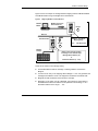
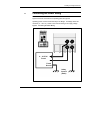
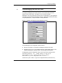
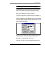
Modicon TSX Momentum Modbus to Ethernet Bridge User Guide 890 USE 155 00 Version 1.0 174 CEV 300 10 Modicon TSX Momentum Modbus to Ethernet Bridge User Guide 890 USE 155 00 31001624 04/99 Breite: 185 mm Höhe: 230 mm Breite: 178 mm Höhe: 216 mm Preface Data, Illustrations, Alterations Data and illustrations are not binding. We reserve the right to alter products in line with our policy of continuous product development. Trademarks All terms used in this publication to denote Schneider Automation products are trademarks of Schneider Automation Incorporated. All other terms used in this publication to denote products may be registered trademarks and/or trademarks of the corresponding corporations. Microsoft and MS-DOS are registered trademarks of Microsoft Corporation, Windows is a brand name of Microsoft Corporation in the USA and other countries. IBM is a registered trademark of International Business Machines Corporation. Intel is a registered trademark of Intel Corporation. Copyright All rights are reserved. No part of this document may be reproduced or transmitted in any form or by any means, electronic or mechanical, including copying, processing or by online file transfer, without permission in writing by Schneider Automation Incorporated. You are not authorized to translate this document into any other language. 1999 Schneider Automation Incorporated. All rights reserved. v Contents Contents Modbus to Ethernet Bridge 174 CEV 300 10 . . . . . . . . . . . . . . . . . . . . . . . . . . . . . . . . . . . . . . . . . . . . . . 9 1.1 1.1.1 1.1.2 1.2 1.2.1 1.2.2 1.3 1.4 Introducing the Modbus to Ethernet Bridge . . . . . . . . . . . . . . . . . . . . . . . . . . . . . . Bridge Applications . . . . . . . . . . . . . . . . . . . . . . . . . . . . . . . . . . . . . . . . . . . . . . . . . . Overview: Installation and Configuration . . . . . . . . . . . . . . . . . . . . . . . . . . . . . . . Mapping Modbus and IP Addresses . . . . . . . . . . . . . . . . . . . . . . . . . . . . . . . . . . . Mapping for a Modbus Master . . . . . . . . . . . . . . . . . . . . . . . . . . . . . . . . . . . . . . . . . Mapping for a Modbus Slave . . . . . . . . . . . . . . . . . . . . . . . . . . . . . . . . . . . . . . . . . . Front Panel Layout . . . . . . . . . . . . . . . . . . . . . . . . . . . . . . . . . . . . . . . . . . . . . . . . . . Specifications . . . . . . . . . . . . . . . . . . . . . . . . . . . . . . . . . . . . . . . . . . . . . . . . . . . . . . . 10 10 11 12 12 12 14 16 Installing the Bridge Hardware . . . . . . . . . . . . . . . . . . . . . . . . . . . . . . 19 2.1 2.1.1 2.1.2 2.2 2.3 2.4 2.5 2.6 2.7 2.8 Mounting the Bridge on the DIN Rail . . . . . . . . . . . . . . . . . . . . . . . . . . . . . . . . . . . Before You Install the Bridge . . . . . . . . . . . . . . . . . . . . . . . . . . . . . . . . . . . . . . . . . . Mounting the Bridge . . . . . . . . . . . . . . . . . . . . . . . . . . . . . . . . . . . . . . . . . . . . . . . . . Connecting the Power Wiring . . . . . . . . . . . . . . . . . . . . . . . . . . . . . . . . . . . . . . . . . Connecting the Serial Cable (RJ45 Port) . . . . . . . . . . . . . . . . . . . . . . . . . . . . . . . Compatible Modbus Devices and Cables . . . . . . . . . . . . . . . . . . . . . . . . . . . . . . . Modbus Cable Pinouts . . . . . . . . . . . . . . . . . . . . . . . . . . . . . . . . . . . . . . . . . . . . . . . Connecting the Serial Cable (Wiring Terminals) . . . . . . . . . . . . . . . . . . . . . . . . . . Setting the Serial Port Switch . . . . . . . . . . . . . . . . . . . . . . . . . . . . . . . . . . . . . . . . . Connecting the Ethernet Cable . . . . . . . . . . . . . . . . . . . . . . . . . . . . . . . . . . . . . . . . 20 20 20 21 22 23 24 26 27 28 Configuring the Bridge . . . . . . . . . . . . . . . . . . . . . . . . . . . . . . . . . . . . . 29 3.1 3.1.1 3.1.2 3.2 3.3 3.4 3.5 3.5.1 3.5.2 3.5.3 3.5.4 3.5.5 890–USE–155–00 Breite: 178 mm Before You Start . . . . . . . . . . . . . . . . . . . . . . . . . . . . . . . . . . . . . . . . . . . . . . . . . . . . . Configuration Overview . . . . . . . . . . . . . . . . . . . . . . . . . . . . . . . . . . . . . . . . . . . . . . . Safety . . . . . . . . . . . . . . . . . . . . . . . . . . . . . . . . . . . . . . . . . . . . . . . . . . . . . . . . . . . . . . Connecting by the RS–232 Port . . . . . . . . . . . . . . . . . . . . . . . . . . . . . . . . . . . . . . . Connecting by Telnet (IP Address Not Assigned) . . . . . . . . . . . . . . . . . . . . . . . . Connecting by Telnet (IP Address Assigned) . . . . . . . . . . . . . . . . . . . . . . . . . . . . Using the Configuration Menu . . . . . . . . . . . . . . . . . . . . . . . . . . . . . . . . . . . . . . . . . Configuration Menu . . . . . . . . . . . . . . . . . . . . . . . . . . . . . . . . . . . . . . . . . . . . . . . . . . Modbus Master Device: Additional Menu Items . . . . . . . . . . . . . . . . . . . . . . . . . Configuration Options: 1 ... 5 . . . . . . . . . . . . . . . . . . . . . . . . . . . . . . . . . . . . . . . . . Viewing and Changing Configuration Parameters . . . . . . . . . . . . . . . . . . . . . . . . Commands: Default settings, Save, Quit without save . . . . . . . . . . . . . . . . . . 30 30 30 31 32 33 34 34 34 35 35 35 vii Contents 3.6 3.7 3.8 3.9 3.10 3.10.1 3.10.2 3.10.3 3.10.4 Option 1: Network/IP Settings . . . . . . . . . . . . . . . . . . . . . . . . . . . . . . . . . . . . . . . . Option 2: Serial and Mode Settings . . . . . . . . . . . . . . . . . . . . . . . . . . . . . . . . . . . Option 3: Modem Control Settings . . . . . . . . . . . . . . . . . . . . . . . . . . . . . . . . . . . . Option 4: Advanced Modbus Protocol Settings . . . . . . . . . . . . . . . . . . . . . . . . . . Option 5: Unit ID to IP Address Mapping Table . . . . . . . . . . . . . . . . . . . . . . . . . How the Address Mapping Works . . . . . . . . . . . . . . . . . . . . . . . . . . . . . . . . . . . . . Example: Address Mapping . . . . . . . . . . . . . . . . . . . . . . . . . . . . . . . . . . . . . . . . . . Entering New Address Mapping . . . . . . . . . . . . . . . . . . . . . . . . . . . . . . . . . . . . . . . Exiting the Mapping Menu . . . . . . . . . . . . . . . . . . . . . . . . . . . . . . . . . . . . . . . . . . . . 36 38 39 40 42 42 42 43 43 Using Panel Software . . . . . . . . . . . . . . . . . . . . . . . . . . . . . . . . . . . . . . 45 4.1 4.1.1 4.1.2 4.2 4.2.1 4.2.2 4.2.3 Using Concept or Modsoft . . . . . . . . . . . . . . . . . . . . . . . . . . . . . . . . . . . . . . . . . . . . Software Versions . . . . . . . . . . . . . . . . . . . . . . . . . . . . . . . . . . . . . . . . . . . . . . . . . . . Modbus Slave Address . . . . . . . . . . . . . . . . . . . . . . . . . . . . . . . . . . . . . . . . . . . . . . . Using Other Software . . . . . . . . . . . . . . . . . . . . . . . . . . . . . . . . . . . . . . . . . . . . . . . . Intellution FIX MMI . . . . . . . . . . . . . . . . . . . . . . . . . . . . . . . . . . . . . . . . . . . . . . . . . . . WinTech Modscan . . . . . . . . . . . . . . . . . . . . . . . . . . . . . . . . . . . . . . . . . . . . . . . . . . . Worderware MMI . . . . . . . . . . . . . . . . . . . . . . . . . . . . . . . . . . . . . . . . . . . . . . . . . . . . 46 46 46 47 47 47 47 Glossary . . . . . . . . . . . . . . . . . . . . . . . . . . . . . . . . . . . . . . . . . . . . . . . . . . . 49 viii 890–USE–155–00 Modbus to Ethernet Bridge 174 CEV 300 10 H Introducing the Modbus to Ethernet Bridge H Mapping Modbus and IP Addresses H Front Panel Layout H Specifications 1 9 Modbus to Ethernet Bridge 1.1 Introducing the Modbus to Ethernet Bridge 1.1.1 Bridge Applications The Modicon Modbus to Ethernet Bridge provides a means for transacting messages between Ethernet TCP/IP devices and Modbus serial devices. It supports up to eight concurrent transactions between Modbus Master and Slave devices, handling the conversion of TCP/IP and Modbus RTU/ASCII protocols transparently to the user application. Ethernet nodes using TCP/IP can function as Modbus Masters, originating messages to the Bridge for delivery to Modbus Slave devices connected to the Bridge’s Modbus port. The Bridge forwards the messages to the Slave devices using Modbus RTU or ASCII protocol and returns their responses to the Master. Figure 1 shows a typical application in which a Bridge connects two Modbus Masters on Ethernet to several Modbus Slave serial devices. Figure 1 Bridging Between Ethernet and Modbus Ethernet Bridge 174 CEV 300 10 Modbus The bridge also allows multiple Modbus networks to be linked together across an Ethernet connection. Multiple Bridges can furnish an Ethernet link between widely separated Modbus networks. This extends the message path beyond the cable lengths allowed for serial connections, and allows a Master on any Modbus network to access Slave devices on another network. 10 Modbus to Ethernet Bridge Figure 2 shows a typical application in which three Bridges join Modbus networks through a common Ethernet link. Figure 2 Bridging Between Multiple Modbus Networks Modbus Ethernet Bridges (3 units) 174 CEV 300 10 Modbus Modbus 1.1.2 Overview: Installation and Configuration The Bridge is designed for easy ‘snap’ mounting on a standard DIN rail. Its front panel has connectors for power, ground, Ethernet and Modbus cables. It has a switch for selecting either an RS–232 or RS–422/485 interface for the Modbus port. Indicators show the status of communication at the Ethernet and Modbus ports. The Bridge contains a configuraton utility program stored in its non–volatile memory. With this utility you can assign the Bridge’s Ethernet and Modbus parameters, using an ASCII terminal at the serial port or a Telnet connection over Ethernet. The Bridge contains a factory–assigned MAC address that is derived from the serial number printed on the Bridge’s label. This allows you to establish an Ethernet connection to the Bridge to assign its IP address and the other parameters for your application. 11 Modbus to Ethernet Bridge 1.2 Mapping Modbus and IP Addresses The Bridge maps messages between Modbus and IP addresses according to the type of device you have configured at its Modbus port. 1.2.1 Mapping for a Modbus Master When you configure a Modbus Master device at the Bridge’s serial port, you can assign up to eight entries into an internal mapping table that is maintained in the Bridge’s memory. You enter your intended mapping into the table during your configuration of the Bridge. Each table entry maps a single Modbus address, or a range of addresses, to a destination IP address. When the Bridge receives a message from the Master, it searches the mapping table for an entry matching the Modbus address in the message. If one is found, the Bridge sends the message to the IP address for that entry. If a matching entry is not found, the Bridge returns an exception response to the Master application. Note that the original Modbus address is retained in the message transmitted to the IP destination. If the remote IP node is another Bridge, the message’s Modbus address can be used to identify a Slave device at that Bridge’s serial port. 1.2.2 Mapping for a Modbus Slave When you configure a Modbus Slave device or network with multiple Slaves at the Bridge’s serial port, you have two options for routing messages to a Slave destination. You assign your choice during your configuration of the Bridge. Your options are: Message address routing; or, Fixed address routing. You can specify that the Bridge must route each message to the Slave device that is identified in the Modbus address field of the message. This allows you to address any Slave device in a network of up to 247 devices at the Bridge’s Modbus port. You can specify that the Bridge must route all messages to one fixed Slave address that you define in the Bridge’s configuration. With this option the Modbus address field is ignored, and each message is routed to that fixed Slave address only. This limits addressing to a single device at the port. 12 Modbus to Ethernet Bridge Figure 3 shows an example of message address mapping between a Modbus Master and a Modbus Slave using two Bridges with an Ethernet link. Figure 3 Mapping Modbus and IP Addresses Modbus Master Modbus message to Slave address 10 Bridge A Ethernet Modbus – IP Address Mapping Entry: 192.168.001.024 Bridge 010 : 192.168.001.024 B Modbus Slave(s) Bridge routes message to Slave according to user–defined setup: Message Slave Address (10) or Fixed Slave Address (1 ... 247) These are the events in the message routing: H The Modbus Master sends its message containing address 10 decimal to Bridge A. H You have set an entry in the mapping table in Bridge A. Your entry specifies that messages with address 10 are to be mapped to IP address 192.168.001.024. H Bridge B has that IP address and receives the message. H Depending on the option you set in Bridge B, the message is routed either to the Modbus Slave device at address 10 as specified in the message, or to a fixed Slave address in the range 1 ... 247. 13 Modbus to Ethernet Bridge 1.3 Front Panel Layout Figure 4 Front Panel Layout 1 2 3 4 5 6 7 8 MODBUS 9 10 11 15 12 13 16 17 14 18 ETHERNET 14 19 20 21 22 Modbus to Ethernet Bridge Table 1 Front Panel Components (See Figure 4) Item 1 Component Wire terminal Name RxD or Rx – 2 Wire terminal CTS or Rx + 3 Wire terminal RTS or Tx + 4 Wire terminal TxD or Tx – 5, 6, 7 8 9 10 Wire terminal Wire terminal Reset switch LED (Red) 11 LED (Green) NC GND RST Fault or Configuration Ready 12 LED (Yellow) Active Ethernet 13 LED (Green) Link Good 14 Connector (RJ45) Ethernet port 15 Connector (RJ45) Modbus port 16 LED (Yellow) Modbus Tx 17 LED (Yellow) Modbus Rx 18 Switch 19 20 21 22 Wire terminal Wire terminal Wire terminal Wire terminal Modbus interface selection DC + Ground DC – Ground Purpose Modbus signal: RS–232: RxD (Receive Data) RS–422.485: RxD– (Receive Data –) Modbus signal: RS–232: CTS (Clear to Send) RS–422/485: RxD+ (Receive Data +) Modbus signal: RS–232: RTS (Request to Send) RS–422/485: TxD– (Transmit Data +) Modbus signal: RS–232: TxD (Transmit Data) RS–422/485: TxD– (Transmit Data –) No connection Modbus signal ground Push to reset and initialize Bridge ON: Fault in Bridge communication (or) Bridge is in Configuration Menu ON: Bridge is ready for communication on both ports Flashing: Indicates activity at Bridge’s Ethernet port ON: Bridge has good connection at Ethernet port RJ45 connector for Ethernet 10BaseT cable RJ45 connector for Modbus RS–232 or RS–485 cable Flashing: Indicates transmission or upload at Modbus port Flashing: Indicates reception at Modbus port UP: Modbus port is RS–232 DOWN: Modbus port is RS–422/485 Operating power, positive Earth ground Operating power, negative Earth ground 15 Modbus to Ethernet Bridge 1.4 Specifications Table 2 Power Parameter Operating Power, Nominal Operating Power Range Maximum Power Drain Connection Fuse Specification 12 or 24 V dc 9 ... 30 V dc 3W Screw terminals External, supplied by customer. Fuse value according to supply voltage (see Maximum Power Drain) Screw terminals provided for power ground and safety (Earth) ground Grounding Table 3 Environmental Parameter Temperature, Operating Humidity, Operating Table 4 Connector 16 Specification Ethernet v2 encapsulation TCP/IP Version 4 RJ45 connector for 10baseT cable Serial Interface Parameter Modbus Protocol Serial Protocol Baud Rate Connector Limits 0...60_ C ambient 20 ... 90% RH, non–condensing Ethernet Interface Parameter Protocol Table 5 Reference IEC 68–2–14 IEC 68–2–3 Specification RTU or ASCII Switch selectable, RS–232 or RS–485 Supports RS–232 RTS/CTS handshaking RS–485 setting supports RS–422 devices Supports 2–wire and 4–wire RS–485 Supports up to 16 RS–485 devices 300 ... 38400 +/– 2% RJ45 connector, screw terminals RJ45 port connects to Modicon M1, Compact, 984 Slot Mount controllers by direct cable. Cable adapters and adapter kits are available for other products. Modbus to Ethernet Bridge Table 6 Packaging Parameter Dimensions Enclosure Material Weight, Product Weight, Shipping Mounting Method Table 7 Description 35 x 95 x 60 mm (1.4 x 3.7 x 2.4 in) High–impact plastic 0.5 kg (1.0 lb) 0.9 kg (2.0 lb) DIN rail: DIN EN S0 022 (35 mm) Agency Approval Parameter UL, CSA, CE FM Specification Approved Pending 17 Installing the Bridge Hardware H Mounting the Bridge on the DIN Rail H Connecting the Power Wiring H Connecting the Serial Cable (RJ45 Port) H Compatible Modbus Devices and Cables H Modbus Cable Pinouts H Connecting the Serial Cable (Wiring Terminals) H Setting the Serial Port Switch H Connecting the Ethernet Cable 2 19 Installing the Bridge Hardware 2.1 Mounting the Bridge on the DIN Rail 2.1.1 Before You Install the Bridge The Bridge has an Ethernet MAC address printed on the label on its side panel. The address is required for your Ethernet network administrator to configure the Bridge. Before you install the Bridge on the DIN rail, write down the MAC address and give it to your network administrator. The label may not be visible after you install the Bridge. Warning COMMUNICATION DISRUPTION HAZARD Connecting any device to an active Ethernet network can disrupt communication on the network. Before you connect the Bridge to your network, and before you apply power to the Bridge, heed the steps in Chapter 3 for configuring the Bridge in your application. Failure to observe this precaution can result in injury or equipment damage. 2.1.2 Mounting the Bridge The Bridge is designed for mounting on a standard DIN rail. Figure 5 shows how to mount the Bridge 1. Note the slot on the Bridge’s rear panel. Position the top edge of the slot over the top edge of the DIN rail. 2. Snap the Bridge into place on the lower edge of the rail. Figure 5 Mounting the Bridge on the DIN Rail 1 2 Mounting 20 Completed Installing the Bridge Hardware 2.2 Connecting the Power Wiring Figure 6 shows the connections for operating power and ground. Operating power must be fused externally to the Bridge. The Bridge draws 3W maximum (9 ... 30 V dc). Select a fuse value according to the supply voltage. Figure 6 Connecting the Power Wiring 9 ... 30 V DC Fused Frame Ground Safety Ground (Earth) 21 Installing the Bridge Hardware 2.3 Connecting the Serial Cable (RJ45 Port) Figure 7 shows serial cable connections for several Modicon CPUs for operation as Modbus Master or Slave devices. The figure also shows a typical connection to a standard PC 9–pin serial port for setting up the Bridge configuration. Table 8 lists other compatible devices and cables. Figure 7 Connecting the Serial Cable (RJ45 Port) Modbus Port (RJ45) A984, E984–24x/25x E984–26x/27x/28x 1 110 CPU 3x/4x/5x/6x 984–38x, 48x, 68x, 78x 1 RJ45 to RJ45 Cables 110 XCA 282 01 (3 ft / 1 m) 110 XCA 282 02 (10 ft / 3 m) 110 XCA 282 03 (20 ft / 6 m) TSX Momentum M1 RJ45 to DB9 Adapters 1 110 XCA 203 01 (Kit) PC with Serial Port 2 110 XCA 203 00 (Pre–wired) 2 NULL Modem M F 22 Installing the Bridge Hardware 2.4 Compatible Modbus Devices and Cables The Bridge connects directly by RJ45 cable to various products shown in Figure 7. Table 8 below lists other Modbus devices and their cable connections to the Bridge. Connections are RS–232 unless indicated otherwise. Cable pinout references are to the diagrams in Figure 8 on page 24. Table 8 Compatible Modbus Devices and Cables Device Part Number MM–PM10–2xx MM–PM10–2xx AS–J478–000 AS–J478–000 AS–J347–001 AS–J375–000 AS–P190–xxx AS–884A–xxx AS–984x–xxx –– AS–P892–000 140 CPU 424 xx 140 CPU 534 xx PC–0984–xxx PC–A984–xxx PC–E984–24x/25x PC–E984–455 PC–M984–xxx NW–BM85xxxx –– 110 VPU 192 00 AS–A584–xxx TSX SCx Device Description PanelMate Plus 1000 (RS232) PanelMate Plus 1000 (RS422) Modbus Modem, Fixed Modem Control Modbus Modem, Variable Modem Control 184/384 Controller Modbus Interface Micro 84 Controller Modbus Interface P190 Programming Panel 884 Controller 984A, B, X Controller PC Serial Port, 9–Pin ASCII/RIO Interface Quantum Controller, 486 Quantum Controller, 586 984 Controller, 38x/48x/68x/78x Slot Mount 984 Controller, Compact 984 Controller, Compact 984 Controller, 484 Replacement Micro–984 Controller BM85 Bridge Multiplexer Generic Modbus Serial Device, 9–Pin Programmer, Handheld 584A, L, M Controller TSX Controllers, Modbus Interface Cable Pinout (Figure 8) A B C D E E E E E F G G G G G G G G G G H See 584 Note See TSX Note 584 Note Use cable AS–W192–XXX with Adapter 110 XCA 204 02, pinouts in Figure 8 cable E. TSX Note TSX Controller products offer multiple options for cable connection to the Bridge. Refer to your product guidebook for more information. 23 Installing the Bridge Hardware 2.5 Modbus Cable Pinouts References in this figure are to the devices listed in Table 8 on page 23. Figure 8 Modbus Cable Pinouts A Adapter Kit: DB9M 2 3 5 Shield B Adapter Kit: 110 XCA 203 01 DB9M 1 4 5 6 9 Shield C D 24 Adapter Kit: DB25M 1 2 3 7 4 6 20 110 XCA 203 01 Wire RJ45 Red 4 Black 3 Green 5 White 8 Wire Black Red Green Yellow Brown White RJ45 E Adapter Kit: 110 XCA 204 01 DB25M Wire RJ45 3 Red 4 2 Black 3 20 Blue 1 7 Green 5 6 Orange 2 4 Yellow 6 5 Brown 7 1 White 8 F Adapter Kit: 110 XCA 203 02 3 4 5 6 7 8 110 XCA 204 01 Wire RJ45 White 8 Red 4 Black 3 Green 5 Adapter Kit: 110 XCA 204 01 DB25M Wire RJ45 2 Red 4 3 Black 3 6 Blue 1 7 Green 5 20 Orange 2 5 Yellow 6 4 Brown 7 1 White 8 DB9F 2 3 4 6 5 7 8 Shield Wire Red Black Orange Green White RJ45 4 3 2 5 6 7 8 G Adapter Kit: 110 XCA 203 01 DB9M Wire RJ45 2 Red 4 3 Black 3 5 Green 5 6 Orange 2 7 Yellow 6 8 Brown 7 Shield White 8 H Adapter: None RJ45 (Prog) 1 2 3 4 5 6 7 8 RJ45 (Bridge) 2 1 4 3 5 6 7 8 Installing the Bridge Hardware Figure 9 shows the layout of DB9–RJ45 and DB25–RJ45 Adapter Kits available from Schneider Automation. Each kit contains three jumper wires and a pin insertion tool. Follow the pinout diagrams in Figure 8 for assembling the adapter for your product. Figure 9 DB to RJ45 Adapter Kits DB9M (110 XCA 203 01) Pin 1 Pin 1 DB9F (110 XCA 203 02) Pin 1 DB25M (110 XCA 204 01) Pin 1 Pin 1 DB25F (110 XCA 204 02) Pin 1 25 Installing the Bridge Hardware 2.6 Connecting the Serial Cable (Wiring Terminals) Figure 10 shows the connection for serial cables at the Bridge’s wiring terminals. Figure 10 Connecting the Serial Cable (Wiring Terminals) RxD CTS Terminating Resistor 120 Ω 1/8 W R RS–232 Signal Signal Data+ Data– Ground RxD– RxD+ TxD+TxD– Ground R 26 Signal RTS TxD Ground R R RS–485 RS–485 / RS–422 2–Wire 4–Wire Installing the Bridge Hardware 2.7 Setting the Serial Port Switch Figure 11 shows the front panel switch for setting the Bridge’s serial port interface. Before you place the Bridge into service, set the switch for the type of interface used in your application: H UP: RS–232 interface. H DOWN: RS–422 or RS–485 interface. Figure 11 Setting the Serial Port Switch Serial Port Switch UP: RS–232 DOWN: RS–422 or RS–485 Warning COMMUNICATION DISRUPTION HAZARD The serial port switch is a hardware function. It is not sensed by the Bridge’s firmware. Changing the switch setting while the Bridge is operating can disrupt communication on the network. Do not change the switch setting unless you have first verified that it will be safe for your application. Failure to observe this precaution can result in injury or equipment damage. 27 Installing the Bridge Hardware 2.8 Connecting the Ethernet Cable Figure 12 shows the RJ45 port connection for the 10baseT Ethernet cable. Figure 12 Connecting the Ethernet Cable Ethernet Port (RJ45) Warning COMMUNICATION DISRUPTION HAZARD Connecting any device to an active Ethernet network can disrupt communication on the network. Before you connect the Bridge to your network, and before you apply power to the Bridge, heed the steps in Chapter 3 for configuring the Bridge in your application. Failure to observe this precaution can result in injury or equipment damage. 28 Configuring the Bridge H Before You Start H Connecting by the RS–232 Port H Connecting by Telnet (IP Address Not Assigned) H Connecting by Telnet (IP Address Assigned) H Using the Configuration Menu H Option 1: Network/IP Settings H Option 2: Serial and Mode Settings H Option 3: Modem Control Settings H Option 4: Advanced Modbus Protocol Settings H Option 5: Unit_ID to IP Address Mapping Table 3 29 Configuring the Bridge 3.1 Before You Start 3.1.1 Configuration Overview Your Bridge must be configured to match your system application. Before you start to configure the Bridge, get the Bridge’s Ethernet and serial port parameters from your network administrator. Here is your check list for obtaining the configuration information: 3.1.2 H Ethernet IP address. H Ethernet Gateway address, if applicable to your Bridge’s network. H Serial port interface: RS–232, RS–422, RS–485. H Serial port communication: Baud rate, Data bits, Parity mode, Stop bits. H Serial port modem controls: RTS/CTS timing values. H Serial port device: Modbus Master or Modbus Slave. H Modbus Protocol: RTU or ASCII. H Modbus Timeout values: Character timeout, Message timeout. H Modbus Slave only: Address source from Unit_ID header, or Fixed address. H Modbus Slave only: Allowing broadcasts to serial port: Enable or Disable. H Modbus Master only: Mapping of Modbus Slave addresses to IP addresses. Safety Warning COMMUNICATION DISRUPTION HAZARD When you view or change the configuration of a running Bridge, you will be restarting it on the network. This will disrupt communication with the Bridge. Ensure that this action will not cause any undesirable effect on your application. Failure to observe this precaution can result in injury or equipment damage. Warning DUPLICATE ADDRESS HAZARD Having two or more devices with the same IP address can cause unpredictable operation of your network. Ensure that you will be assigning a unique IP address to the Bridge. Failure to observe this precaution can result in injury or equipment damage. 30 Configuring the Bridge 3.2 Connecting by the RS–232 Port To configure the Bridge at its local RS–232 port, use a serial terminal emulation program and a modem cable. See Figure 7 for a connection example. Regardless of any serial parameters currently set into the Bridge for a user application, it will always use the following parameters for setup: 9600 baud, 8 data bits, No parity, 1 Stop bit (9600,8,N,1). Set your emulator to these parameters. Figure 13 Example: RS–232 Serial Terminal Emulator Properties Force the Bridge into its Configuration mode as follows: H Ensure the emulator is connected to the Bridge’s serial port and ready. H Hold down the ‘X’ key on your emulator keyboard. While holding the key down, initialize the Bridge by cycling its power or by pressing its Reset button. The Bridge will enter its configuration mode, and you will see this opening screen: Schneider Automation, Inc. – Modbus Bridge (174 CEV 300 10) Serial Number 101–161 Software Version V01.00 (990402) Press Enter to go into Setup Mode, wait to close At this screen, press <Enter> to go to the Configuration Menu (see Section 3.5). 31 Configuring the Bridge Connecting by Telnet (IP Address Not Assigned) 3.3 If the Bridge does not yet have an IP address stored in its memory, you can establish an initial connection using its MAC address. This will allow you to access the Bridge’s Configuration Menu, assign an IP address, and make it persistent in the Bridge. If you are not sure about whether your Bridge has a stored IP address, you must connect at its serial port and access its Configuration Menu. Section 3.2 describes how to connect to the serial port. Telnet Host Requirement In order to use Telnet to set an initial IP address for the Bridge, your Telnet host must be on the same Ethernet subnetwork as the Bridge, both physically and in its IP range. Otherwise the configuration will not work. Step 1 Get the Bridge’s MAC Address. The Bridge’s MAC address is printed on the label on its side panel. Example: MAC address: 00 20 4A 01 65 A1. Step 2 Issue an “arp” Command to the Bridge. Open a Console or DOS window. Issue an arp command to the Bridge with this syntax: Syntax: arp –s Example (UNIX): Example (DOS): <IP_address> arp arp –s –s <MAC_address> 192.168.1.23 192.168.1.23 00:20:4A:01:65:A1 00–20–4A–01–65–A1 Step 3 Connect by Telnet to Port 1. Open a Telnet connection to the IP address you assigned in Step 2, using port 1. This connection will fail, but the Bridge will change its IP address to the one in this Telnet connection. This will allow you to make your final connection for configuring the Bridge. Step 4 Connect by Telnet to Port 9999. Open a new a Telnet connection to the IP address using port 9999. This connection will succeed. You should now see the Bridge’s opening screen: Schneider Automation, Inc. – Modbus Bridge (174 CEV 300 10) Serial Number 101–161 Software Version V01.00 (990402) Press Enter to go into Setup Mode, wait to close At this screen, press <Enter> to go to the Configuration Menu (see Section 3.5). 32 Configuring the Bridge 3.4 Connecting by Telnet (IP Address Assigned) If the Bridge already has an IP address stored in its memory, and you know that address, you can establish a Telnet connection to the Bridge using port 9999. If you do not know the IP address currently stored in the Bridge, you can find that address by connecting to the Bridge’s serial port and accessing its Configuration Menu. Section 3.2 describes how to connect to the serial port. If you want to verify the existence of an Ethernet device at a known IP address, you can use the PING utility. Refer to your Ethernet documents for a description of PING. Telnet Host Requirement In order to use Telnet to set an initial IP address for the Bridge, your Telnet host must be on the same Ethernet subnetwork as the Bridge, both physically and in its IP range. Otherwise the configuration will not work. Figure 14 Example: Telnet Connection When the connection is established, you should see the Bridge’s opening screen: Schneider Automation, Inc. – Modbus Bridge (174 CEV 300 10) Serial Number 101–161 Software Version V01.00 (990402) Press Enter to go into Setup Mode, wait to close At this screen, press <Enter> to go to the Configuration Menu (see Section 3.5). 33 Configuring the Bridge 3.5 Using the Configuration Menu When the Bridge enters its configuration mode it displays its opening screen: Schneider Automation, Inc. – Modbus Bridge (174 CEV 300 10) Serial Number 101–161 Software Version V01.00 (990402) Press Enter to go into Setup Mode, wait to close At this screen, press <Enter> to see the Configuration Menu. 3.5.1 Configuration Menu The Configuration Menu shows the Bridge’s current settings. Here is an example: Modbus Bridge Firmware Setup, Schneider Automation, Inc. 1) Network/IP Settings: IP Address ................... 192.168.1.23 Default Gateway .............. 192.168.1.30 Netmask ...................... 255.255.255.000 2) Serial & Mode Settings: Protocol ..................... Modbus/RTU, Slave(s) attached Serial Interface ............. 19200,8,E,1,RS232 3) Modem Control Settings: RTS Output ................... Fixed High/Active 4) Advanced Modbus Protocol Settings: Slave Addr/Unit ID Source .... Modbus/TCP header Modbus Serial Broadcasts ..... Disabled Character, Message Timeout ... 00050 ms, 05000 ms Commands: D)efault settings, S)ave, Q)uit without save Select Command or Parameter (1...4) to change: __ 3.5.2 Modbus Master Device: Additional Menu Items If the serial port has already been configured for a Modbus Master device, menu item 4 will omit references to a Slave device, showing only the following: 4) Advanced Modbus Protocol Settings: Character, Message Timeout ... 00100 ms, 05000 ms Menu item 5 will show current mapping between Modbus addresses and IP addresses. 5) Unit ID –> IP Address Table: (followed by the current mapping table). 34 Configuring the Bridge 3.5.3 Configuration Options: 1 ... 5 These are your configuration options. Each option is described in detail in the following sections of this book: 3.5.4 H 1) Network/IP Settings: H 2) Serial & Mode Settings: See Section 3.7. H 3) Modem Control Settings: See Section 3.8. H 4) Advanced Modbus Protocol Settings: H 5) Unit ID –> IP Address Table: See Section 3.6. See Section 3.9. See Section 3.10. Viewing and Changing Configuration Parameters When you view the Bridge’s configuration parameters, you can retain their current values or change them. Retaining the Current Value In all cases, if you press <Enter> when the current value is displayed, you will retain the current value. For example, if the Bridge’s current values are as shown below, pressing <Enter> at each field will retain that current value: IP Address : (192) .(168) .(001) .(023) Changing a Value To change a value, type the new value into the field at the point shown on your screen. For example, to change the Bridge’s IP address to: 192.168.1.24: IP Address : (192) .(168) .(001) .(023) 24 In this example, you would type the 24 immediately following the (023). Then press <Enter> for the Bridge to accept your entry. 3.5.5 Commands: Default settings, Save, Quit without save These are your commands: H E D)efault settings: Restores the Bridge’s factory–installed default settings for all parameters except the Ethernet IP settings. H S S)ave: Stores the current settings into the Bridge’s memory, and exits the configuration. The Bridge will restart immediately using the current settings. H Q Q)uit without save: Exits the configuration. The Bridge will restart immediately using the settings it had prior to the last Save. 35 Configuring the Bridge 3.6 Option 1: Network/IP Settings When you select option 1 on the Configuration Menu, the Bridge displays its current Ethernet settings. Here is an example: IP Address : (192) .(168) .(001) .(023) Set Gateway IP Address (Y): Gateway IP Address : (192) .(168) .(001) .(030) Set Netmask (N for default) (Y): (255) .(255) .(255) .(000) IP Address The four entry fields for the IP address are shown as parenthesis ( ). To retain the Bridge’s current IP address, just press <Enter> at each field. To assign a new IP address, enter it into each field. IP 0.0.0.0: Note that setting the IP address to all zero (0.0.0.0) causes the Bridge to be in an “Address Not Assigned” status. It reports its address as: 0.0.0.0/DHCP. Disregard the reference to DHCP. Set Gateway IP Address The Gateway IP Address is used only if your Ethernet network is larger than one continuous network (it contains subnetworks). Each node within the subnetwork can directly reach all the other nodes within the same subnetwork. If the Bridge’s subnetwork has a gateway to another subnetwork, the Gateway IP Address parameter identifies the gateway’s address. Set Netmask If the Bridge’s subnetwork has a gateway node, the Bridge needs to know how to recognize which IP addresses it can communicate with directly on its own subnetwork and which addresses it must refer to the gateway node. The Netmask (subnetwork mask) specifies which portion of the an IP address defines devices on the local subnetwork, and which portion defines the entire subnetwork the devices are on. By comparing IP addresses with the subnetwork mask, the Bridge can determine which addresses are on its subnetwork and which are not. Users can define different subnetwork masks to support their requirements. For example, common “Class C” IP addresses assume a default subnetwork mask of 36 Configuring the Bridge 0xFFFFFF00 or 255.255.255.0, using the lower 8 bits for the host part of the IP address. This allows up to 255 devices on the local subnetwork. This default mask is the example shown in the menu above. If the user desires to have multiple subnetworks with up to 32 devices on each the subnetwork mask could define 5 “host” bits or 255.255.255.224. With this setting, the decimal value 224 configures the lower 8 bits of the address, with the upper 3 of these bits addressing up to 8 subnetworks, and the lowest 5 bits forming the part of the address for the 32 local devices. If you wish to specify a subnetwork mask, enter Y at the menu prompt and then enter your values for the mask. Enter N to use the default subnetwork mask of 255.255.255.0. 37 Configuring the Bridge 3.7 Option 2: Serial and Mode Settings When you select option 2 on the Configuration Menu, the Bridge displays its current serial port settings. Here is an example: Attached Device (1=Slave, 2=Master) (001): Serial Protocol (1=Modbus/RTU, 2=Modbus/ASCII) (001): Interface Type (1=RS232, 2=RS422, 3=RS485) (001): Enter Serial Parameters (9600,8,E,1): Attached Device Identify the type of Modbus device (Slave or Master) attached to the Bridge’s serial port. The default is Slave. Serial Protocol Identify the type of Modbus protocol (RTU or ASCII) to be used at the serial port. The default is RTU. Interface Type Identify the type of communication interface (RS232, RS422 or RS485) used at the serial port. The default is RS232. Enter Serial Parameters Enter the serial communication parameters used at the port, delimited by commas: <baudrate>,<databits>,<parity>,<stopbits> The defaults are: 9600,8,E,1. The allowed values are: 38 H Baud rate: 300, 1200, 2400, 4800, 9600, 19200, 38400 H Data bits: 7, 8 H Parity: E, O, N H Stop bits: 1, 2. Configuring the Bridge 3.8 Option 3: Modem Control Settings When you select option 3 on the Configuration Menu, the Bridge displays: RTS/CTS Mode (1=Fixed, 2=Variable) (001): RTS/CTS Mode RTS (Request to Send) and CTS (Clear to Send) are serial port signals that coordinate the starting and stopping of data requests between the Bridge and its port device. You can customize the RTS/CTS mode. The options are: Fixed or Variable. The default is Fixed. This causes the Bridge to apply RTS/CTS with no time delays. if you enter 2 to select the Variable option, you can specify timing values to allow a slower device to respond in the RTS/CTS dialog. When you choose this option the Bridge displays: Delay after output RTS (0–1275 msec, 5 ms resolution) (00000): Wait for CTS to go active (N): Delay after CTS going active (0–1275 msec, 5 ms res) (00000): Delay dropping RTS after TX (0–1275 msec, 5 ms res) (00000): Example If you select the RTS/CTS Variable mode and enter the following values: RTS/CTS Mode (1=Fixed, 2=Variable) (001): 2 Delay after output RTS (0–1275 msec, 5 ms resolution) (00000): Wait for CTS to go active (N): 200 Y Delay after CTS going active (0–1275 msec, 5 ms res) (00000): Delay dropping RTS after TX (0–1275 msec, 5 ms res) (00000): 250 300 ... you are specifying that after the Bridge asserts RTS it should wait up to 200 ms for the serial port device to respond with CTS. It will then wait 250 ms before sending data to the device. It will wait 300 ms before dropping RTS at the end of transmission. Your new values will be now be shown in the Bridge’s Configuration Menu: 3) Modem Control Settings: RTS Output ................... Variable, Delay 0200 ms, Hold 0250 ms CTS Input to TX Delay ........ 0300 ms 39 Configuring the Bridge 3.9 Option 4: Advanced Modbus Protocol Settings When you select option 4 on the Configuration Menu, the Bridge displays parameters for the type of Modbus device (Slave or Master) at its serial port. Slave Device: Slave device parameters are: Slave Address (0 for auto, or 1...255 fixed) (000): Allow Modbus Broadcasts (1–Yes, 2=No) (002): Character Timeout (10–1275 msec, 5 ms res) (00050): Message Timeout (500–60000 msec, 250 ms res) (05000): Master Device: Master device parameters are: Character Timeout (10–1275 msec, 5 ms res) (00050): Message Timeout (500–60000 msec, 250 ms res) (05000): Slave Address The Bridge’s Slave Address parameter specifies how the Bridge will direct messages received from Ethernet to a Slave device at the serial port. Each message originated from a Modbus Master contains a Unit_ID field that addresses a Modbus Slave destination device. The Bridge can be configured to use that Unit_ID address as received, or to substitute a fixed address instead. Setting the Slave Address parameter to 0 (zero) configures the Bridge to use the Unit_ID field as received in the message. It will pass the message out its Modbus port to the Slave device addressed in the Unit_ID field. Setting the Slave Address parameter to any non–zero value causes the Bridge to always use that fixed value as the Slave address for all messages sent out its Modbus port, regardless of the Unit_ID contained in the message. This routes all messages to a single device. The allowable non–zero range for entering this value is 1 ... 255 decimal. Note that Modbus Slave addresses are valid in the range 1 ... 247 only. The default is 0 (zero), specifying the Bridge to use the received Unit_ID field. 40 Configuring the Bridge Allow Modbus Broadcasts This parameter specifies whether the Bridge may allow a Modbus Broadcast message to be sent to Slave devices at its serial port, or not allow those messages. Broadcast messages are those received by the Bridge containing a Unit_ID of 0 (zero). If Modbus Broadcasts are allowed, broadcast messages are passed to the serial port as received with the Unit_ID contents of 0 (zero). If Modbus Broadcasts are not allowed, the Unit_ID in the message is disregarded and the message is sent to Slave address 1 at the serial port. The default is to not allow Broadcast messages to the serial port. Character Timeout This parameter sets the timeout value between successive characters in messages. If this timeout is exceeded, the Bridge returns an error response to the originating Master. Typically RTU protocol already contains a 3.5 character timeout, but some serial devices might have internal interrupts or other delays which can cause pauses of 5 to 10 characters during transmission. This parameter can be set to accommodate those devices. The allowable range is 10 ... 1275 msec in 5 msec increments. The default is 50 msec. Message Timeout This parameter sets the timeout value for the expected response from a Slave device. If a response is not received within this time, the Bridge continues with other tasks if any are pending from other Master devices. The Master application must provide its own method of handling the message timeout. The allowable range is 500 ... 60000 msec (0.5 ... 60 sec) in 250 msec increments. The default is 5000 msec (5 sec). 41 Configuring the Bridge 3.10 Option 5: Unit ID to IP Address Mapping Table If you have specified the Bridge’s serial port Attached Device parameter as a Modbus Master (see Section 3.7), you will need to map the Slave addresses received in messages from that Master to their intended IP address destinations. The Bridge maps the one–byte Modbus Slave address to an IP address for delivery on Ethernet. 3.10.1 How the Address Mapping Works The Bridge contains an address mapping table with eight entries. Each entry maps a Modbus Slave address (range 1 ... 247 decimal) to a standard IP address (XXX.XXX.XXX.XXX). When the Bridge receives a message from the Master at its serial port, the Bridge searches the table for a match between the message’s Slave address and a Slave address entry in the mapping table. If a match is found, the Bridge forwards the message to the IP address specified in that location in the table. If a match is not found, a message timeout will occur. If a match is found, but there is not an active TCP connection at the IP address, a message timeout will occur. The Master application must provide its own method of handling the message timeout. The Bridge begins its search at table location 1, and continues in the sequence 1, 2 ... 8. It stops at the first location which matches the Slave address, and sends the message to the corresponding IP address. Thus any duplicate entry, if one exists in the table, will be ignored. If you have configured the serial port for a Modbus Master, you must use the mapping table to associate the ranges of Slave addresses in your Master application to the IP destination addresses for those Slaves. 3.10.2 Example: Address Mapping If you have configured the serial port for a Modbus Master, and have entered your mapping, it will appear on the Bridge’s initial Configuration Menu. Here is an example. 5) Unit ID –> IP Address Table: 001–001: 192.168.001.020 002–002: 192.168.001.021 003–003: 192.168.001.022 010–010: 192.168.001.024 011–247: 192.168.001.025 In this example, the Bridge maps Modbus Slave address 1 to IP address 192.168.1.20. It maps Slave addresses 2, 3, 10 as shown in the table. It maps any Slave address in the range 11 ... 247 to IP address 192.168.1.25. 42 Configuring the Bridge 3.10.3 Entering New Address Mapping When you select option 5 on the Configuration Menu, the Bridge displays it current mapping. Then it prompts: A)dd, D)elete, E)xit –– select function: Adding a New Map Entry Press A to add a new entry into the mapping table. The Bridge will prompt you to enter the new mapping values. The values will go into the first available (empty) table location. Here is an example: Modbus addr from (000): Modbus addr to (000): 1 1 Slave IP address (192) .(168) . (001) .(020) Deleting a Map Entry Press D to delete an entry from the mapping table. The Bridge will prompt you to enter the number of the table location you want to delete. Here is an example: Delete entry number: 1 Changing an Existing Map Entry If you want to change an existing entry in the mapping table, you must first delete that entry and then add your changes as a new entry. 3.10.4 H Press D to delete the current entry from the table. H Press A to add a new entry into the table, supplying the values for the new entry. Exiting the Mapping Menu Press E to exit the Mapping Table menu and return to the initial Configuration Menu. The Configuration Menu will display the new mapping (see Section 3.10.2). Note that when you return to the Configuration Menu, you must select Save on that menu to save the address mapping in the Bridge’s memory. Selecting Save will also restart the Bridge. See Section 3.5 for a description of your Configuration Menu. 43 Using Panel Software H Using Concept or Modsoft H Using Other Software 4 45 Using Panel Software 4.1 Using Concept or Modsoft 4.1.1 Software Versions To support Modbus/TCP to the Bridge, you need Concept version 2.1 or later, or Modsoft version 2.6 or later. Set the communications parameters as follows: H Protocol: TCP/IP H Dest_Port: 502 H Dest_Index: Modbus Slave address Note that the Bridge contains an internal Slave Address configuration option which might affect the delivery of messages to a Slave device at its serial port. With this option, the Bridge may be configured internally to use the Dest_Index address exactly as received in the message, or it may be configured to steer all messages to a fixed Slave address, ignoring the Dest_Index address. H 4.1.2 TCP/IP Address: as required. Modbus Slave Address This is an additional explanation of how the Bridge uses the Modbus Slave address. In a Modbus TCP message sent to the Bridge, the Slave address (defined in panel software as the Dest_Index address) is stored in the Unit_ID field of the message. This field is used to address a unique Slave device on a Modbus network which may contain multiple Slave devices. The Bridge’s internal configuration contains a Slave Address parameter which can be set to override the Unit_ID address received in the message. Section 3.9 of this book describes how to set up the Slave Address parameter. If the parameter is set to 0 (zero), the message will be delivered to the Slave device whose address is defined in the Unit_ID field. If the parameter is set to a non–zero value (range 1 ... 255), the message will be delivered to the Slave device at that numerical address, regardless of the contents of the Unit_ID field. For example: If you are accessing the device at Modbus Slave address 34, you must: 46 H Set the Dest_Index field to 34, and H Ensure the Bridge’s internal Slave Address parameter is configured to 0 (zero). Using Panel Software 4.2 Using Other Software 4.2.1 Intellution FIX MMI The Bridge allows Windows workstations with Intellution FIX software to access Modbus devices by TCP/IP over Ethernet. The current version of this software does not support the Modbus/TCP Unit_ID field. Therefore if you have configured the Bridge for a Slave device at its serial port, you must configure the Bridge’s internal Slave Address parameter for that device. This restricts the Bridge to a single Slave device at its port. Refer to your software product’s documentation for further information. 4.2.2 WinTech Modscan WinTech supplies ModScan32 software, which can select and poll coils and registers from various Modbus RTU/ASCII and Modbus TCP devices. This software supports the Modbus/TCP Unit_ID field, so RS–485 multiple–drop configurations are supported through the Bridge. Refer to your software product’s documentation for further information. 4.2.3 Worderware MMI The Bridge allows Windows workstations with Wonderware software to access Modbus devices by TCP/IP over Ethernet. You will need the Wonderware Modicon Ethernet I/O Server software, at version 7.0.0.15 or higher. The current version of this software does not support the Modbus/TCP Unit_ID field. Therefore if you have configured the Bridge for a Slave device at its serial port, you must configure the Bridge’s internal Slave Address parameter for that device. This restricts the Bridge to a single Slave device at its port. Refer to your software product’s documentation for further information. 47 Glossary 5 address On a network, the identification of a station. In a frame, a grouping of bits that identifies the frame’s source or destination. API Application Program Interface. The specification of functions and data used by one program module to access another; the programming interface that corresponds to the boundary between protocol layers. ARP Address Resolution Protocol. A network layer protocol used to determine the physical address which corresponds to the IP address for a host on the network. ARP is a sub–protocol which operates under TCP/IP. BOOTP Bootstrap Protocol. A TCP/IP–based protocol that allows a host to configure itself dynamically. Provides a means to assign a host its IP address, typically without user intervention. bps Bits per second. bridge A device that connects two or more physical networks which use the same protocol. Bridges read frames and decide whether to transmit or block them based on their destination address. client A computer process requesting service from other computer processes. dest_idx The destination field in a Modbus message. Corresponds to the Modbus device addressed in the message. 49 Glossary default gateway The IP address of the network or host to which all packets addressed to an unknown network or host are sent. The default gateway is typically a router or other device. DHCP Dynamic Host Configuration Protocol. A network protocol used to configure IP addresses dynamically. DHCP is an extension of BOOTP. DNS Domain Name System. A protocol within TCP/IP used to find IP addresses based on host names. field A logical grouping of contiguous bits that convey one kind of information, such as the start or end of a message, an address, data or an error check. frame A group of bits which form a discrete block of information. Frames contain network control information or data. The size and composition of a frame is determined by the network technology being used. framing types Two common framing types are Ethernet II and IEEE 802.3. FTP File Transfer Protocol. A networking protocol used to exchange files between stations on a network or over the Internet. gateway A device which connects networks with dissimilar network architectures and which operates at the Application Layer. This term may refer to a router. host A node on a network. hostname A domain name given to a specific computer on a network and used to address that computer. HTTP HyperText Transport Protocol. A protocol used to deliver hypertext documents. hub A device which connects a series of flexible and centralized modules to create a network. 50 Glossary ICMP Internet Control Message Protocol. A protocol within TCP/IP used to report errors in datagram transmission. Internet The global interconnection of TCP/IP based computer communication networks. IP Internet Protocol. A common network layer protocol. IP is most often used with TCP. IP Address Internet Protocol Address. A 32–bit address assigned to hosts using TCP/IP. layer In the OSI model, a portion of the structure of a device which provides defined services for the transfer of information. MAC Address Media Access Control address. The hardware address of a device. A MAC address is assigned to an Ethernet TCP/IP module in the factory. network Interconnected devices sharing a common data path and protocol for communication. node An addressable device on a communications network. OSI model Open System Interconnection model. A reference standard describing the required performance of devices for data communication. Produced by the International Standards Organization. packet The unit of data sent across a network. PING Packet Internet Groper. A program used to test whether a destination on a network can be reached. port An access point for data entry or exit within a host using TCP services. protocol Describes message formats and a set of rules used by two or more devices to communicate using those formats. 51 Glossary repeater A device that connects two sections of a network and conveys signals between them without making routing decisions or filtering packets. router A device that connects two or more sections of a network and allows information to flow between them. A router examines every packet it receives and decides whether to block the packet from the rest of the network or transmit it. The router will attempt to send the packet through the network by the most efficient path. server Provides services to clients. This term may also refer to the computer on which the service is based. socket The association of a port with an IP address, serving as an identification of sender or recipient. stack The software code which implements the protocol being used. In the case of the NOE modules it is TCP/IP. STP Shielded Twisted Pair. A type of cabling consisting of several strands of wire surrounded by foil shielding, twisted together. subnet A physical or logical network within an IP network, which shares a network address with other portions of the network. subnet mask Used to indicate which bits in an IP address identify a subnet. switch A network device which connects two or more separate network segments and allows traffic to be passed between them. A switch determines whether a frame should be blocked or transmitted based on its destination address. TCP Transmission Control Protocol. TCP/IP A protocol suite consisting of the Transmission Control Protocol and the Internet Protocol; the suite of communications protocols on which the Internet is based. 52 Glossary UDP User Datagram Protocol. A protocol which transmits data over IP. URL Uniform Resource Locator. The network address of a file. UTP Unshielded Twisted Pair. A type of cabling consisting of insulated cable strands which are twisted together in pairs. Winsock The Microsoft implementation of the Windows Sockets networking API based on the Berkeley UNIX Sockets interface for supporting TCP/IP. WWW World Wide Web. A hypertext–based, distributed information system in which clients and servers are freely available. 53 Modicon, Square D and Telemacanique are PLC brand names from Schneider. These products are sold in the US by Square D; in Canada, Latin America, Europe, Asia, Asia/Pacific and Middle East by Schneider; in Germany by AEG Schneider Automation; in China and Persian Gulf by Schneider Automation; in South Africa by ASA Systems Automation; in Austria by Online. United States: Schneider Automation, Inc. One High Street North Andover, MA 01845 Tel: (1) 978–794–0800 Fax: (1) 978–975–9400 France: Schneider Automation S.A. 245, Route des Lucioles - BP147 F–06903 Sophia - Antipolis Cedex Tel: (33) 92 96 20 00 Fax: (33) 93 65 37 15 Germany: Schneider Automation GmbH Steinheimer Strasse 117 D–63500 Seligenstadt Tel: (49) 6182 81–2584 Fax: (49) 6182 81–2860