1
Chapter 5
Signal Connections
Analog Inputs
The 7344/7334 controllers have the following ADC input signals:
•
Analog Input <1..4>—The 7344/7334 controllers include an
eight-channel multiplexed, 12-bit ADC capable of measuring ±10 V,
±5 V, 0–10 V, and 0–5 V inputs. ADC channels 1 through 4 are
brought out externally on the 68-pin motion I/O connector. ADC
channels 5 through 8 are connected internally, as shown in Table 5-2.
These signals can be used for ADC test and calibration.
Table 5-2. Internal ADC Channels
ADC Input
Signal
5
Filtered +5 V
6
Floating (NC)
7
Analog Reference (7.5 V)
8
Analog Input Ground
You can configure each ADC channel for motion feedback, simple
A/D conversion, or both.
You can read the digital value of analog voltage on any of the eight
ADC channels of the controller by using the Read ADC function.
Table 5-3 shows the range of values read back and the voltage
resolution for each setting. The voltage resolution is in volts per least
significant bit (V/LSB).
Table 5-3. Analog Input Voltage Ranges
Input Range
Binary Values
Resolution
±10 V
–2,048 to 2,047
0.0049 V/LSB
±5 V
–2,048 to 2,047
0.0024 V/LSB
0–10 V
0 to 4,095
0.0024 V/LSB
0–5 V
0 to 4,095
0.0012 V/LSB
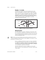
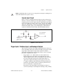
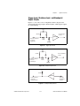
As indicated in Figure 5-3, when configured as analog feedback, an
analog sensor acts like a limited range absolute position device with a
full-scale position range. You can map any ADC channel as feedback
to any axis.
You can enable and disable individual ADC channels in software.
Disable unused ADC channels for the highest multiplexer scan rate
7344/7334 Hardware User Manual
5-12
ni.com